steering SKODA ROOMSTER 2012 1.G User Guide
[x] Cancel search | Manufacturer: SKODA, Model Year: 2012, Model line: ROOMSTER, Model: SKODA ROOMSTER 2012 1.GPages: 194, PDF Size: 4.8 MB
Page 60 of 194
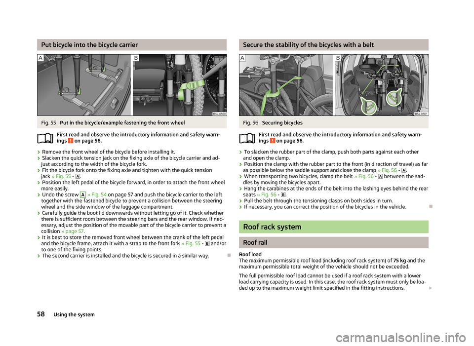
Put bicycle into the bicycle carrier
Fig. 55
Put in the bicycle/example fastening the front wheel
First read and observe the introductory information and safety warn-
ings on page 56.
›
Remove the front wheel of the bicycle before installing it.
› Slacken the quick tension jack on the fixing axle of the bicycle carrier and ad-
just according to the width of the bicycle fork.
› Fit the bicycle fork onto the fixing axle and tighten with the quick tension
jack »
Fig. 55 - .
› Position the left pedal of the bicycle forward, in order to attach the front wheel
more easily.
› Undo the screw A
» Fig. 54 on page 57
and push the bicycle carrier to the left
together with the fastened bicycle to prevent a collision between the steering
wheel and the side window of the luggage compartment.
› Carefully guide the boot lid downwards without letting go of it. Check whether
there is sufficient room between the steering bars and the rear window. If nec-
essary, adjust the position of the movable part of the bicycle carrier to prevent a
collision » page 57 .
› It is best to store the removed front wheel between the crank of the left pedal
and the bicycle frame, attach it with a strap to the front fork » Fig. 55 - and/or
to one of the fixing points.
› The second carrier is installed and the bicycle is secured in a similar way. Ð
ä Secure the stability of the bicycles with a belt
Fig. 56
Securing bicycles
First read and observe the introductory information and safety warn-
ings on page 56.
›
To slacken the rubber part of the clamp, push both parts against each other
and open the clamp.
› Position the clamp with the rubber part to the front (in direction of travel) as far
as possible below the saddle support and close the clamp » Fig. 56
- .
› When transporting two bicycles, clamp the belt
» Fig. 56 - between the sad-
dles by moving the bicycles apart.
› Hang the carabines at the ends of the belt into the lashing eyes behind the rear
seats » Fig. 56 - .
› Pull the belt through the tensioning clasps on both sides in turn.
› If necessary, you can correct the position of the bicycles in the vehicle. Ð Roof rack system
Roof rail
Roof load
The maximum permissible roof load (including roof rack system) of 75 kg and the
maximum permissible total weight of the vehicle should not be exceeded.
The full permissible roof load cannot be used if a roof rack system with a lower
load carrying capacity is used. In this case, the roof rack system must only be loa-
ded up to the maximum weight limit specified in the fitting instructions. £
ä
58 Using the system
Page 78 of 194
Starting-off and Driving
Starting and stopping the engine
ä
Introduction
This chapter contains information on the following subjects:
Adjusting the steering wheel position 77
Electrohydraulic power steering 77
Electronic immobiliser 77
Ignition lock 78
Starting engine 78
Switching the engine off 78
WARNING
■ Never adjust the steering wheel when the vehicle is moving only when the
vehicle is stationary!
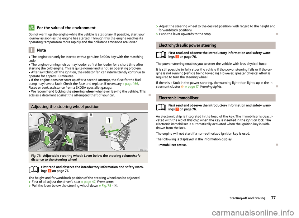
■ Maintain a distance of 25 cm 1
to the steering wheel
» Fig. 78 on page 77
- . Not maintaining this minimum distance will mean that the airbag system
will not be able to properly protect you - hazard!
■ The lever for adjusting the steering wheel must be locked whilst driving so
that the position of the steering wheel cannot accidently change during the
journey - risk of accident!
■ If the steering wheel is adjusted further towards the head, the protection
provided by the driver airbag in the event of an accident is reduced. Check
that the steering wheel is aligned to the chest. ■ When driving, hold the steering wheel with both hands firmly on the outer
edge in the 9 o'clock and 3 o'clock position. Never hold the steering wheel in
the 12 o'clock position or in any other way (e.g. in the middle or inner edge of
the steering wheel). In such cases, you could injure the arms, hands and head
when the driver airbag is deployed.
■ When driving, the ignition key must always be in the position 2
» Fig. 79 on
page 78 (ignition switched on) without the engine running. This position is
indicated by the warning lights coming on. If this is not the case, it could result
in unexpected locking of the steering wheel - risk of accident! WARNING (Continued)
■ Only pull the ignition key from the ignition lock when the vehicle has come
to a complete stop (by applying the handbrake). Otherwise the steering wheel
could block - risk of accident!
■ When leaving the vehicle, the ignition must always be removed. This is par-
ticularly important if children are left in the vehicle. Otherwise the children
could, for example, start the engine - risk of accident or injury!
■ Never leave the engine running in unventilated or closed rooms. The ex-
haust gases of the engine contain besides the odorless and colourless carbon
monoxide a poisonous gas - hazard! Carbon monoxide can cause unconscious-
ness and death. ■ Never leave the vehicle unattended with the engine running.
■ Never switch off the engine before the vehicle is stationary - risk of acci-
dent! CAUTION
■ You will place great stresses on the power steering system if the steering is
turned to full lock when the vehicle is stationary. Turning the steering to full lock
in such a situation will be accompanied by noises. Never leave the steering wheel
at full lock for more than 15
seconds when the engine is running - risk of damag-
ing the power steering!
■ The starter may only be operated (ignition key position 3
» Fig. 79 on
page 78), if the engine is not running. The starter or engine can be damaged if
the starter is activated when the engine is running. ■ Let go of the ignition key as soon as the engine starts otherwise the starter
could be damaged. ■ Avoid high engine revolutions, full throttle and high engine loads as long as the
engine has not yet reached its operating temperature - risk of damaging the en-
gine!
■ Do not tow start the engine - danger of damaging the engine! On vehicles with
a catalytic converter, unburnt fuel may get into the catalytic converter where it
may ignite. This in turn may damage the catalytic converter. The battery from an-
other vehicle can be used as a jump-start aid » page 163, Jump-starting.
■ Do not switch the engine off immediately at the end of your journey after the
engine has been operated over a prolonged period at high loads but leave it to
run at an idling speed for about 1
minute. This prevents any possible accumulation
of heat when the engine is switched off. £
76 Using the system
Page 79 of 194
For the sake of the environment
Do not warm up the engine while the vehicle is stationary. If possible, start your
journey as soon as the engine has started. Through this the engine reaches its
operating temperature more rapidly and the pollutant emissions are lower. Note
■ The engine can only be started with a genuine ŠKODA key with the matching
code. ■ The engine running noises may louder at first be louder for a short time after
starting the cold engine. This is quite normal and is not an operating problem. ■ After switching off the ignition, the radiator fan can intermittently continue to
operate for approx. 10
minutes.
■ If the engine does not start up after a second attempt, the fuse for the fuel
pump may have a fault. Check the fuse and replace, if necessary » page 166,
Fuses or seek assistance from a
ŠKODA specialist garage.
■ We recommend locking the steering wheel whenever leaving the vehicle. This
acts as a deterrent against the attempted theft of your car. ÐAdjusting the steering wheel position
Fig. 78
Adjustable steering wheel: Lever below the steering column/safe
distance to the steering wheel
First read and observe the introductory information and safety warn-
ings on page 76.
The height and forward/back position of the steering wheel can be adjusted.
› First of all adjust the driver's seat
» page 47, Front seats .
› Pull the lever below the steering wheel down
» Fig. 78 - .
ä ›
Adjust the steering wheel to the desired position (with regard to the height and
forward/back position).
› Push the lever upwards to the stop. Ð Electrohydraulic power steering
First read and observe the introductory information and safety warn-
ings on page 76.
The power steering enables you to steer the vehicle with less physical force.
It is still possible to fully steer the vehicle if the power steering fails or if the en-
gine is not running (vehicle being towed in). However, greater physical effort is
required to turn the steering wheel.
If there is a fault in the power steering, the warning light then lights up in the in-
strument cluster » page 17, Warning lights . Ð Electronic immobiliser
First read and observe the introductory information and safety warn-
ings on page 76.
An electronic chip is integrated in the head of the key. The immobiliser is deacti-
vated with the aid of this chip when the key is inserted in the ignition lock. The
electronic immobiliser is automatically activated when the ignition key is with-
drawn from the lock.
The engine will not start if a non-authorized ignition key is used.
The following is displayed in the information display: Immobilizer active. Ð
ä
ä
77
Starting-off and Driving
Page 80 of 194
Ignition lock
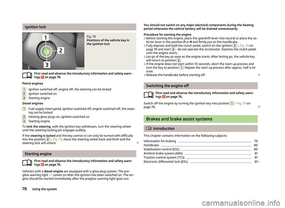
Fig. 79
Positions of the vehicle key in
the ignition lock
First read and observe the introductory information and safety warn-
ings on page 76.
Petrol engines
Ignition switched off, engine off, the steering can be locked
Ignition switched on
Starting engine
Diesel engines Fuel supply interrupted, ignition switched off, engine switched off, the steer-
ing can be locked.
Heating glow plugs on, ignition switched on
Starting engine
To lock the steering , with the ignition key withdrawn, turn the steering wheel
until the steering locking pin engages audibly.
If the steering is locked and the key cannot or can only be turned with difficulty
into the position 2
» Fig. 79, move the steering wheel back and forth and the
steering lock will unlock. ÐStarting engine
First read and observe the introductory information and safety warn-
ings on page 76.
Vehicles with a diesel engine are equipped with a glow plug system. The pre-
glow warning light comes on after the ignition has been switched on. The en-
gine should be started immediately after the preglow warning light goes out.
ä 1
2
3
1
2
3
ä You should not switch on any major electrical components during the heating
period otherwise the vehicle battery will be drained unnecessarily.
Procedure for starting the engine
› Before starting the engine, place the gearshift lever into neutral or place the se-
lector lever in the position P or N and firmly put on the handbrake.
› Fully depress and hold the clutch pedal, switch on the ignition 2
» Fig. 79 on
page 78 and start 3
- do not operate the accelerator. Depress the clutch pedal
until the engine starts.
› Let go of the key as soon as the engine starts. After letting go, the vehicle key
will return to position 2
.
› If the engine does not start within 10
seconds, abort the start-up process and
turn the key to position 1
. Repeat the start-up process after approx. half a mi-
nute.
› Release the handbrake before starting off. Ð Switching the engine off
First read and observe the introductory information and safety warn-
ings on page 76.
Switch off the engine by turning the ignition key into position 1
» Fig. 79 on
page 78. Ð Brakes and brake assist systems
ä
Introduction
This chapter contains information on the following subjects:
Information for braking 79
Handbrake 80
Stabilisation control (ESC) 80
Antilock brake system (ABS) 81
Traction control system (TCS) 81
Electronic differential lock (EDL) 81
£
ä
78 Using the system
Page 82 of 194
Faults in the brake surface
If it is found that the braking distance has suddenly become longer and that the
brake pedal can be depressed further, the brake system may be faulty. Visit a
ŠKODA specialist garage immediately and adjust your style of driving appropriate-
ly as you will not know how great the damage is.
Low brake fluid level
An insufficient level of brake fluid may result in problems in the brake system. The
level of the brake fluid is monitored electronically
» page 18, Brake system .
Brake booster
The brake booster increases the pressure generated with the brake pedal. The
brake booster only operates when the engine is running. ÐHandbrake
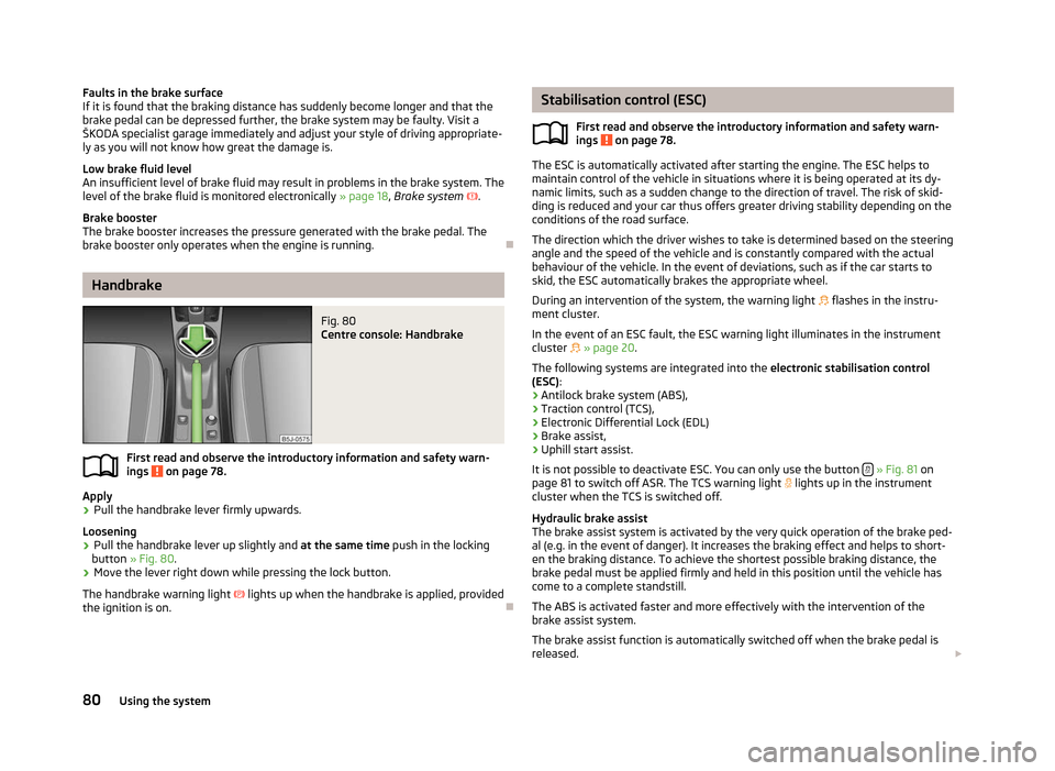
Fig. 80
Centre console: Handbrake
First read and observe the introductory information and safety warn-
ings on page 78.
Apply
› Pull the handbrake lever firmly upwards.
Loosening
› Pull the handbrake lever up slightly and
at the same time push in the locking
button » Fig. 80 .
› Move the lever right down while pressing the lock button.
The handbrake warning light lights up when the handbrake is applied, provided
the ignition is on. Ð
ä Stabilisation control (ESC)
First read and observe the introductory information and safety warn-
ings on page 78.
The ESC is automatically activated after starting the engine. The ESC helps to
maintain control of the vehicle in situations where it is being operated at its dy-
namic limits, such as a sudden change to the direction of travel. The risk of skid-
ding is reduced and your car thus offers greater driving stability depending on the
conditions of the road surface.
The direction which the driver wishes to take is determined based on the steering
angle and the speed of the vehicle and is constantly compared with the actual
behaviour of the vehicle. In the event of deviations, such as if the car starts to
skid, the ESC automatically brakes the appropriate wheel.
During an intervention of the system, the warning light flashes in the instru-
ment cluster.
In the event of an ESC fault, the ESC warning light illuminates in the instrument
cluster » page 20.
The following systems are integrated into the electronic stabilisation control
(ESC):
› Antilock brake system (ABS),
› Traction control (TCS),
› Electronic Differential Lock (EDL)
› Brake assist,
› Uphill start assist.
It is not possible to deactivate ESC. You can only use the button » Fig. 81 on
page 81 to switch off ASR. The TCS warning light lights up in the instrument
cluster when the TCS is switched off.
Hydraulic brake assist
The brake assist system is activated by the very quick operation of the brake ped-
al (e.g. in the event of danger). It increases the braking effect and helps to short-
en the braking distance. To achieve the shortest possible braking distance, the
brake pedal must be applied firmly and held in this position until the vehicle has
come to a complete standstill.
The ABS is activated faster and more effectively with the intervention of the
brake assist system.
The brake assist function is automatically switched off when the brake pedal is
released. £
ä
80 Using the system
Page 87 of 194
START/STOP
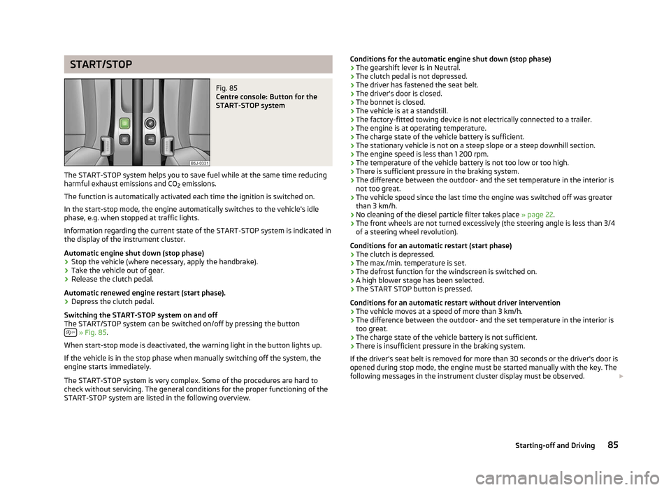
Fig. 85
Centre console: Button for the
START-STOP system
The START-STOP system helps you to save fuel while at the same time reducing
harmful exhaust emissions and CO 2 emissions.
The function is automatically activated each time the ignition is switched on.
In the start-stop mode, the engine automatically switches to the vehicle's idle
phase, e.g. when stopped at traffic lights.
Information regarding the current state of the
START-STOP system is indicated in
the display of the instrument cluster.
Automatic engine shut down (stop phase)
› Stop the vehicle (where necessary, apply the handbrake).
› Take the vehicle out of gear.
› Release the clutch pedal.
Automatic renewed engine restart (start phase).
› Depress the clutch pedal.
Switching the
START-STOP system on and off
The START/STOP system can be switched on/off by pressing the button » Fig. 85.
When start-stop mode is deactivated, the warning light in the button lights up.
If the vehicle is in the stop phase when manually switching off the system, the
engine starts immediately.
The
START-STOP system is very complex. Some of the procedures are hard to
check without servicing. The general conditions for the proper functioning of the
START-STOP system are listed in the following overview. Conditions for the automatic engine shut down (stop phase)
› The gearshift lever is in Neutral.
› The clutch pedal is not depressed.
› The driver has fastened the seat belt.
› The driver's door is closed.
› The bonnet is closed.
› The vehicle is at a standstill.
› The factory-fitted towing device is not electrically connected to a trailer.
› The engine is at operating temperature.
› The charge state of the vehicle battery is sufficient.
› The stationary vehicle is not on a steep slope or a steep downhill section.
› The engine speed is less than 1
200 rpm.
› The temperature of the vehicle battery is not too low or too high.
› There is sufficient pressure in the braking system.
› The difference between the outdoor- and the set temperature in the interior is
not too great.
› The vehicle speed since the last time the engine was switched off was greater
than 3 km/h.
› No cleaning of the diesel particle filter takes place
» page 22.
› The front wheels are not turned excessively (the steering angle is less than 3/4
of a steering wheel revolution).
Conditions for an automatic restart (start phase)
› The clutch is depressed.
› The max./min. temperature is set.
› The defrost function for the windscreen is switched on.
› A high blower stage has been selected.
› The START STOP button is pressed.
Conditions for an automatic restart without driver intervention
› The vehicle moves at a speed of more than 3 km/h.
› The difference between the outdoor- and the set temperature in the interior is
too great.
› The charge state of the vehicle battery is not sufficient.
› There is insufficient pressure in the braking system.
If the driver's seat belt is removed for more than 30 seconds or the driver's door is
opened during stop mode, the engine must be started manually with the key. The
following messages in the instrument cluster display must be observed. £
85
Starting-off and Driving
Page 88 of 194
Messages in the instrument cluster display (valid for vehicles without
Information display)
ERROR START STOP Error in the START-STOP system
START STOP NOT POSSIBLE Automatic engine shut down is not
possible.
START STOP ACTIVE Automatic engine shut down (stop
phase)
SWITCH OFF IGNITION Switch off the ignition.
START MANUALLY Start the engine manually.WARNING
■ The brake servo unit and power steering only operate if the engine is run-
ning.
■ Never let the vehicle roll with the engine switched off. CAUTION
Deactivate the START-STOP system before driving through water on the
street » page 124. Note
■ Changes to the outdoor temperature can have an effect on the internal temper-
ature of the vehicle battery even after several hours. If the vehicle remains out-
doors for a long time in minus temperatures or in direct sunlight, it can take sev-
eral hours until the internal temperature of the vehicle battery reaches a suitable
temperature for proper operation of the
START STOP system.
■ If the Climatronic is running in automatic mode, under certain conditions, the
engine may not switch off automatically. Ð86
Using the system
Page 89 of 194

Automatic gearbox
Automatic gearbox
ä
Introduction
This chapter contains information on the following subjects:
Introductory information 87
Starting-off and driving 88
Selector lever positions 88
Manual shifting of gears (Tiptronic) 89
Selector lever lock 89
Kickdown function 90
Dynamic shift programme 90
Emergency programme 90
Selector lever-emergency unlocking 91
WARNING
■ Do not depress the accelerator if changing the position of the selector lever
when the vehicle is stationary and the engine is running - risk of accident!
■ Never move the selector lever into position R or P when driving - risk of an
accident!
■ When the engine is running and the vehicle is stationary, it is necessary to
hold the car with the brake pedal in all the positions of the selector lever (ex-
cept P and N) since the power transmission is never completely interrupted,
also not when the engine is idling - the vehicle creeps.
■ The selector lever must be placed into position P and the handbrake firmly
applied before the bonnet can be opened and work on the running engine can
be completed - risk of accident! The safety guidelines must always be ob-
served » page 136, Engine compartment . WARNING (Continued)
■ If stopping on a hill (downhill gradient), never try to maintain the vehicle sta-
tionary with the gear engaged by means of the
“accelerator pedal”, i.e. by let-
ting the clutch slip. This can lead to overheating of the clutch. If there is a risk
of overheating of the clutch due to overload, the clutch is opened automati-
cally and the vehicle rolls backward - risk of accident!
■ If you have to stop on a slope, depress and hold the brake pedal to prevent
the vehicle from rolling back.
■ On a smooth or slippery road surface using the kickdown function can cause
the driven wheels to spin - risk of skidding! CAUTION
■ The double clutch on the automatic gearbox DSG is equipped with an overload
protection. If the uphill function is used when the vehicle is stationary or driving
slowly uphill, the thermal stress on the clutches is increased. ■ If the clutch system overheats, the symbol is shown in the information dis-
play along with the message Gearbox overheated. Stop! Owner's man.! appears.
An audible signal sounds as a warning signal. Stop the vehicle, switch off the en-
gine, and wait until the symbol disappears - risk of gearbox damage! You can
continue your journey as soon as the symbol disappears. Ð Introductory information
First read and observe the introductory information and safety warn-
ings on page 87.
Shifting up and down through the gears is performed automatically. The gearbox
can also be switched to Tiptronic mode. This mode makes it possible for you to
also shift gears manually » page 89.
The engine can only be started when the selector lever is in position P or N . If
the selector lever is not in the P or N positions when locking the steering, switch-
ing the ignition on or off or when leaving the engine on, the following message
will appear in the Information display Move selector lever to position P/N! or, in
the instrument cluster display: P/N
.
At temperatures below -10 °C the engine can only be started in the selector lever
position P 1)
. £
ä
1)
Applies to DSG.
87
Automatic gearbox
Page 94 of 194

Communication
Mobile phones and two-way radio systems
ŠKODA permits the operation of mobile phones and two-way radio systems with
a professionally installed external aerial and a maximum transmission power of
up to 10 watts.
Please refer to a ŠKODA Service Partner for information about the possibilities of
installing and operating mobile phones and two-way radio systems that have a
transmission power of more than 10
W.
Operating mobile phones or two-way radio systems may interfere with the func-
tionality of the electronic systems in your vehicle.
The reasons for this are as follows:
› no external aerial;
› external aerial incorrectly installed;
› transmission power greater than 10 watts. WARNING
■ Concentrate fully at all times on your driving! As the driver you are fully re-
sponsible for road safety. Use the telephone system only to such an extent
that you are in full control of your vehicle at any time.
■ The national regulations for using a mobile phone in a vehicle must be ob-
served.
■ If a mobile phone or a two-way radio system is operated in a vehicle without
an external aerial or an external aerial which has been installed incorrectly,
this can increase the strength of the electromagnetic field inside the vehicle. ■ Two-way radio systems, mobile phones or mounts must not be installed on
airbag covers or within the immediate deployment range of the airbags.
■ Never leave a mobile phone on a seat, on the dash panel or in another area,
from which it can be thrown during a sudden braking manoeuvre, an accident
or a collision - risk of injury.
■ In the event of air transport, the Bluetooth ®
function for the hands-free sys-
tem must be switched off by a specialist garage. Note
■ We recommend that the installation of mobile phones and two-way radio sys-
tems in a vehicle be carried out by a ŠKODA
Service Partner.
■ Not all mobile phones that enable Bluetooth ®
communication are compatible
with the universal telephone preinstallation GSM
II. You can ask an authorised
ŠKODA Service Partner whether your telephone is compatible with the universal
telephone preinstallation GSM II. ■ The range of the Bluetooth ®
connection to the hands-free system is restricted
to the vehicle interior. The range is dependent on local factors, e.g. obstacles be-
tween the devices and mutual interferences with other devices. If your mobile
phone is in a jacket pocket, for example, this can lead to difficulties when estab-
lishing a connection with the hands-free-system or transferring data. Ð Universal telephone preinstallation GSM II
Introductory information
The universal telephone preinstallation GSM
II (hands-free system) includes a
convenience mode for the mobile phone via voice control, the multifunction
steering wheel, the adapter, radio or the navigation system.
The universal telephone preinstallation GSM II comprises the following functions.
› Phone Phonebook » page 93.
› Convenience operation of the telephone via the multifunction steering
wheel
» page 93 .
› Managing telephone calls via the adapter
» page 94.
› Operation of the telephone via the information display
» page 95.
› Voice control of the telephone
» page 96.
› Music playback from the telephone or other multimedia units
» page 97.
All communication between a mobile phone and your vehicle's hands-free system
is established with the help of Bluetooth ®
technology. The adapter serves only
for charging the telephone and for transmitting the signal to the vehicle's exter-
nal aerial. Note
The following guidelines must be observed » page 92, Mobile phones and two-
way radio systems. Ð
92 Using the system
Page 95 of 194
Phone Phonebook
A phone phonebook is part of the hands-free system. This phone phonebook can
be used depending on the type of mobile phone.
After the first connection of the telephone, the system begins to load the phone
book from the phone and the SIM card into the memory of the control unit.
Each time the telephone has established a new connection with the hands-free
system, an update of the relevant phone book is performed. The updating can
take a few minutes. During this time the phone book, which was stored after the
last update was completed, is available. Newly stored telephone numbers are on-
ly shown after the updating has ended. The update is interrupted if a telephone event (e.g. incoming or outgoing call,
voice control dialogue) occurs during the updating procedure. After the telephone
event has ended, the updating starts anew.
The internal phonebook provides 2
500 free memory locations. Each contact can
contain up to 4 numbers.
If the number of contacts loaded exceeds 2 500, the phone book is not complete. ÐOperating the phone on the multifunction steering wheel
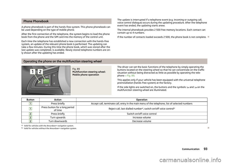
Fig. 89
Multifunction steering wheel:
Mobile phone operation The driver can set the basic functions of the telephone by simply operating the
buttons located on the steering wheel so that he can concentrate on the traffic
situation without being distracted as little as possible by operating the tele-
phone
» Fig. 89 .
This applies only if your vehicle has been equipped with the universal telephone
preinstallation (hands-free system) at the factory.
If the side lights are switched on, the buttons and the symbols and on the
multifunction steering wheel are illuminated.
Button Action Operation1
Press briefly
Accept call, terminate call, entry in the main menu of the telephone, list of selected numbers1 Press button for a long period
of time Reject call, last dialled number
a)
, switch on/off voice control b)2
Press briefly
Switch on/off voice control2
Turn upwards
Increase volume2
Turn downwards
Decrease volumea)
Valid for vehicles with the Amundsen+ navigation system.
b) Valid for vehicles without the Amundsen+ navigation system. Ð
93
Communication