boot SKODA ROOMSTER 2014 1.G User Guide
[x] Cancel search | Manufacturer: SKODA, Model Year: 2014, Model line: ROOMSTER, Model: SKODA ROOMSTER 2014 1.GPages: 204, PDF Size: 14.15 MB
Page 55 of 204
The following applies if your vehicle has been locked using the central locking
button.
› It is not possible to open the doors or the boot lid from the outside (safety
feature, e.g. when stopping at traffic lights etc.).
› The doors can be unlocked and opened from the inside by pulling on the
opening lever of the respective door. By the first pull on the opening lever,
the door is unlocked. By the second pull on the opening lever, the door is
opened .
› If at least one door has been opened, the vehicle cannot be locked.
› In the event of an accident in which the airbags are deployed, the locked
doors are automatically unlocked in order to enable rescuers to gain access
to the vehicle.WARNING■ Doors locked from the inside make it difficult for rescuers to get into the
vehicle in an emergency – risk to life!■
If the safe lock system is switched on » page 50, the door opening lever
and the central locking buttons do not operate.
Remote control
Introduction
This chapter contains information on the following subjects:
Unlocking/locking
52
Synchronization
53
You can use the remote control key to:
› unlock and lock the vehicle,
› unlocking boot lid;
› open and close the windows
» page 57, Window convenience operation .
The transmitter with the battery is housed in the handle of the remote control
key. The receiver is located in the interior of the vehicle. The operating range of the remote control key is approx. 30 m. But this range of the remote control
can be reduced if the batteries are weak.
The key has a fold-open key bit which can be used for unlocking and locking
the car manually and also for starting the engine.
If a lost key is replaced or if the receiver unit has been repaired or replaced, the
system must be initialised by a specialist garage. Only then can the remote
control key be used again.
Note■ The remote control is automatically deactivated when the ignition is switch-
ed on.■
The operation of the remote control may temporarily be affected by interfer-
ence from transmitters close to the car and which operate in the same fre-
quency range (e.g. mobile phone, TV transmitter).
■
The battery must be replaced if the central locking or anti-theft alarm system
does react to the remote control at less than 3 metres away » page 47.
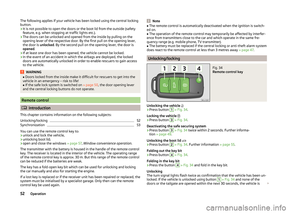
Unlocking/locking
Fig. 34
Remote control key
Unlocking the vehicle
›
Press button
1
» Fig. 34 .
Locking the vehicle
›
Press button
3
» Fig. 34 .
Deactivating the safe securing system
›
Press button
3
» Fig. 34 twice within 2 seconds. Further informa-
tion » page 49 .
Unlocking the boot lid
›
Press button
2
» Fig. 34 . Further information » page 55.
Folding out the key bit
›
Press button
4
» Fig. 34 .
Folding in the key bit
›
Press the button
4
» Fig. 34 and fold in the key bit.
Unlocking
The turn signal lights flash twice as confirmation that the vehicle has been un-
locked. If the vehicle is unlocked using button
1
» Fig. 34 and none of the
doors or the tailgate are opened within the next 30 seconds, the vehicle is
52Operation
Page 56 of 204
automatically locked again and the safe securing system or anti-theft alarm
system is reactivated. This function is intended to prevent the car being un-
locked unintentionally.
In addition, when the car is unlocked, the electrically adjustable seats and ex-
terior mirrors move into the position assigned to this key. The stored setting of
driver seat and exterior mirrors is retrieved.
Locking
The turn signal lights flash once to confirm that the vehicle has been correctly
locked.
If the doors or the boot lid remain open after the vehicle has been locked, the
turn signal lights do not flash until they have been closed.
Note
■ Only operate the remote control when the doors and boot lid are closed and
the vehicle is in your line of sight.■
A ŠKODA partner can also activate/deactivate the acoustic signals on vehi-
cles with an anti-theft alarm system.
Synchronization
If the vehicle does not unlock when the remote control is pressed, the key may
not be synchronised. This can occur when the buttons on the remote control
key are pressed several times outside the operating range of the equipment or
if the battery in the remote control key has been replaced.
Synchronise the key as follows.
›
Press any button on the remote control key.
›
Unlock the door with the key within 1 minute of pressing the button.
Anti-theft alarm system
Introduction
This chapter contains information on the following subjects:
Operation
53
Interior monitor and towing protection
54
The anti-theft alarm system increases the level of protection against people
trying to break into the vehicle.
The alarm system triggers audible and visual signals if an attempt is made to
break into the vehicle (hereafter referred to only as alarm).
Note
■ The working life of the alarm siren is 5 years.■Before leaving the vehicle, check that all the doors and windows are closed
in order to ensure that the anti-theft alarm system is fully operational.■
Coding of the radio remote control and the receiver unit precludes the use of
the radio remote control from other vehicles.
Operation
How is the alarm system activated?
The anti-theft alarm system is activated when the vehicle is locked with the
radio remote control or the key in the driver's door . It is activated 30 seconds
after locking the door.
How is the alarm system deactivated?
The alarm system is deactivated by pressing the button on the remote con-
trol. The anti-theft alarm system is reactivated if the vehicle is not opened
within 30 seconds after transmitting the radio signal.
Triggering the alarm
The alarm is triggered when the following unauthorized actions are carried out
on the locked vehicle.
› Opening the bonnet.
› Opening the boot lid.
› Opening the doors.
› Manipulation of the ignition lock.
› Towing the vehicle
» page 54.
› Movement in the vehicle
» page 54.
› Sudden and significant voltage drop of the electrical system.
› Uncoupling the trailer
» page 129.
If the driver's door of a vehicle with a remote control is unlocked and opened
by the lock cylinder, then the alarm is triggered.
Switching off the alarm
The alarm is turned off by pressing the button on the radio remote control
key or switching on the ignition.
53Unlocking and locking
Page 57 of 204
CAUTIONBefore leaving the vehicle, check that the doors and windows are closed in or-
der to ensure that the alarm system is fully operational.
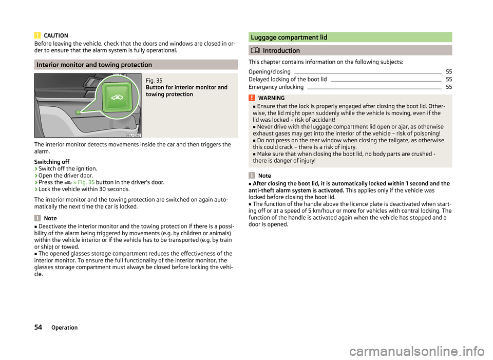
Interior monitor and towing protection
Fig. 35
Button for interior monitor and
towing protection
The interior monitor detects movements inside the car and then triggers the
alarm.
Switching off
›
Switch off the ignition.
›
Open the driver door.
›
Press the
» Fig. 35 button in the driver's door.
›
Lock the vehicle within 30 seconds.
The interior monitor and the towing protection are switched on again auto-
matically the next time the car is locked.
Note
■ Deactivate the interior monitor and the towing protection if there is a possi-
bility of the alarm being triggered by movements (e.g. by children or animals)
within the vehicle interior or if the vehicle has to be transported (e.g. by train
or ship) or towed.■
The opened glasses storage compartment reduces the effectiveness of the
interior monitor. To ensure the full functionality of the interior monitor, the
glasses storage compartment must always be closed before locking the vehi-
cle.
Luggage compartment lid
Introduction
This chapter contains information on the following subjects:
Opening/closing
55
Delayed locking of the boot lid
55
Emergency unlocking
55WARNING■ Ensure that the lock is properly engaged after closing the boot lid. Other-
wise, the lid might open suddenly while the vehicle is moving, even if the
lid was locked – risk of accident!■
Never drive with the luggage compartment lid open or ajar, as otherwise
exhaust gases may get into the interior of the vehicle – risk of poisoning!
■
Do not press on the rear window when closing the tailgate, as otherwise
this could crack – there is a risk of injury.
■
Make sure that when closing the boot lid, no body parts are crushed -
there is danger of injury!
Note
■ After closing the boot lid, it is automatically locked within 1 second and the
anti-theft alarm system is activated. This applies only if the vehicle was
locked before closing the boot lid.■
The function of the handle above the licence plate is deactivated when start-
ing off or at a speed of 5 km/hour or more for vehicles with central locking. The
function of the handle is activated again when the vehicle has stopped and a
door is opened.
54Operation
Page 58 of 204
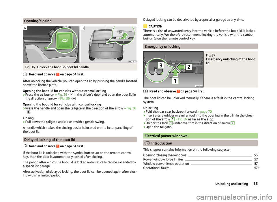
Opening/closingFig. 36
Unlock the boot lid/boot lid handle
Read and observe
on page 54 first.
After unlocking the vehicle, you can open the lid by pushing the handle located
above the licence plate.
Opening the boot lid for vehicles without central locking
›
Press the button
» Fig. 36 -
in the driver's door and open the boot lid in
the direction of arrow » Fig. 36 -
.
Opening the boot lid for vehicles with central locking
›
Press the handle and open the tailgate in the direction of the arrow » Fig. 36
- .
Closing
›
Pull down the tailgate and close it with a gentle swing.
A handle which makes the closing easier is located on the inner panelling of
the boot lid.
Delayed locking of the boot lid
Read and observe
on page 54 first.
If the boot lid is unlocked with the symbol button on the remote control
key, then the door is automatically locked after closing.
The period after which the boot lid is locked automatically can be extended by a specialist garage.
After activation of delayed locking, the boot lid can be opened again after clos-
ing within a limited period.
Delayed locking can be deactivated by a specialist garage at any time.
CAUTION
There is a risk of unwanted entry into the vehicle before the boot lid is locked
automatically. We therefore recommend locking the vehicle with the symbol
button
on the remote control key.
Emergency unlocking
Fig. 37
Emergency unlocking of the boot
lid
Read and observe on page 54 first.
The boot lid can be unlocked manually if there is a fault in the central locking
system.
Unlocking
›
Fold the rear seat backrest forward » page 70.
›
Insert a screwdriver or similar tool into the opening in the trim in the direc-
tion of the arrow
1
» Fig. 37 as far as the stop.
›
Unlock the lock
3
under the trim in the direction of arrow
2
.
›
Open the tailgate.
Electrical power windows
Introduction
This chapter contains information on the following subjects:
Opening/closing the windows
56
Power window force limiter
57
Window convenience operation
57
Operational faults
57
55Unlocking and locking
Page 63 of 204
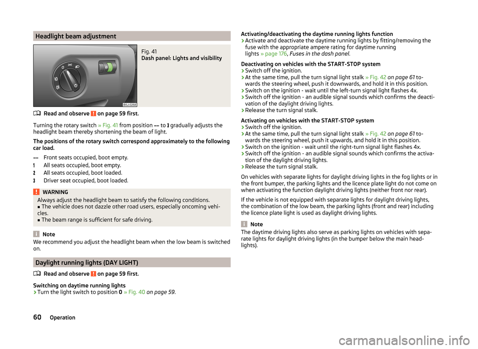
Headlight beam adjustmentFig. 41
Dash panel: Lights and visibility
Read and observe on page 59 first.
Turning the rotary switch » Fig. 41 from position
to
gradually adjusts the
headlight beam thereby shortening the beam of light.
The positions of the rotary switch correspond approximately to the following
car load.
Front seats occupied, boot empty.
All seats occupied, boot empty.
All seats occupied, boot loaded.
Driver seat occupied, boot loaded.
WARNINGAlways adjust the headlight beam to satisfy the following conditions.■The vehicle does not dazzle other road users, especially oncoming vehi-
cles.■
The beam range is sufficient for safe driving.
Note
We recommend you adjust the headlight beam when the low beam is switched
on.
Daylight running lights (DAY LIGHT)
Read and observe
on page 59 first.
Switching on daytime running lights
›
Turn the light switch to position 0 » Fig. 40 on page 59 .
Activating/deactivating the daytime running lights function›Activate and deactivate the daytime running lights by fitting/removing the
fuse with the appropriate ampere rating for daytime running
lights » page 176 , Fuses in the dash panel .
Deactivating on vehicles with the START-STOP system›
Switch off the ignition.
›
At the same time, pull the turn signal light stalk » Fig. 42 on page 61 to-
wards the steering wheel, push it downwards, and hold it in this position.
›
Switch on the ignition - wait until the left-turn signal light flashes 4x.
›
Switch off the ignition - an audible signal sounds which confirms the deacti-
vation of the daylight driving lights.
›
Release the turn signal stalk.
Activating on vehicles with the START-STOP system
›
Switch off the ignition.
›
At the same time, pull the turn signal light stalk » Fig. 42 on page 61 to-
wards the steering wheel, push it upwards, and hold it in this position.
›
Switch on the ignition - wait until the right-turn signal light flashes 4x.
›
Switch off the ignition - an audible signal sounds which confirms the activa-
tion of the daylight driving lights.
›
Release the turn signal stalk.
On vehicles with separate lights for daylight driving lights in the fog lights or in
the front bumper, the parking lights and the licence plate light do not come on
when activating the function daylight driving lights (neither front nor rear).
If the vehicle is not equipped with separate lights for daylight driving lights,
the combination of the low beam, the parking lights (front and rear) including
the licence plate light is used as daylight driving lights.
Note
The daytime driving lights also serve as parking lights on vehicles with sepa-
rate lights for daylight driving lights (in the bumper below the main head-
lights).60Operation
Page 67 of 204
If control of the lights by the door contact switch is enabled (switchA » Fig. 45 is in the position), the light will come on when one of the fol-
lowing occurs.
› The vehicle is unlocked.
› One of the doors is opened.
› The ignition key is removed.
If control of the lights by the door contact switch is enabled (switch A
» Fig. 45
in the
position), the light will go off when one of the following occurs.
› The vehicle is locked.
› The ignition is switched on.
› About 30 seconds after all the doors have been closed.
If a door remains open, or if switch
A
» Fig. 45 is in the
position, the interior
light goes out after 10 minutes to prevent the vehicle battery from discharging.
Interior lighting - version 2
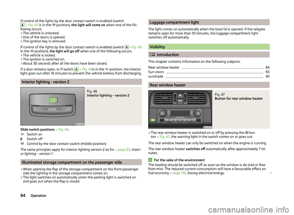
Fig. 46
Interior lighting – version 2
Slide switch positions » Fig. 46 .
Switch on
Switch off
Control by the door contact switch (middle position)
The same principles apply for interior lighting version 2 as for » page 63, Interi-
or lighting - version 1 .
Illuminated storage compartment on the passenger side
›
When opening the flap of the storage compartment on the front passenger
side the lighting in the storage compartment comes on.
›
The light switches on automatically when the parking light is switched on
and goes out when the flap is closed.
Luggage compartment light
The light comes on automatically when the boot lid is opened. If the tailgate remains open for more than 10 minutes, the luggage compartment light
switches off automatically.
Visibility
Introduction
This chapter contains information on the following subjects:
Rear window heater
64
Sun visors
65
sunshade
65
Rear window heater
Fig. 47
Button for rear window heater
›
The rear window heater is switched on or off by pressing the but-
ton » Fig. 47 , the warning light in the switch comes on or goes out.
The rear window heater can only be switched on when the engine is running.
The rear window heater switches off automatically after approximately 7 mi-
nutes.
For the sake of the environment
The heating should be switched off as soon as the window is de-iced or free
from mist. The reduced current consumption will have a favourable effect on
fuel economy » page 116, Saving electrical energy . 64Operation
Page 76 of 204

headrest adjustFig. 62
Head restraint: adjusting/removing
Read and observe
on page 72 first.
Setting height
›
Grasp the side of the head restraint with both hands and push it upwards as
required » Fig. 62 -
.
›
To move the head restraint downwards, press and hold the safety but-
ton » Fig. 62 -
with one hand and push the head restraint down with the
other hand.
Removing/installing
›
Pull the head restraint out of the seat backrest as far as the stop.
›
Press the locking button in the direction of the arrow » Fig. 62 -
and pull
the head restraint out.
›
To re-insert the head restraint, push it far enough down into the seat back-
rest until the locking button clicks into place.
Boot
Introduction
This chapter contains information on the following subjects:
Class N1 vehicles
74
Fastening elements
74
Folding hooks
74
Fixing nets
75
Fixing floor covering of the luggage compartment
75Boot cover75Net partition76
Please observe the following for the purpose of maintaining good handling
characteristics of your vehicle:
›
Distribute loads as evenly as possible.
›
Place heavy objects as far forward as possible.
›
Attach the items of luggage to the lashing eyes or using the fixing
net » page 74 .
In the event of an accident, even small and light objects gain so much kinetic
energy that they can cause severe injuries.
The magnitude of the kinetic energy is dependent on the speed at which the
vehicle is travelling and the weight of the object.
Example: In the event of a frontal collision at a speed of 50 km/h, an object
weighing 4.5 kg produces energy corresponding to 20 times its own weight.
This means that it results in a weight of approx. 90 kg “ ”.
WARNING■ Store the objects in the boot and attach them to the lashing eyes.■Loose objects can be thrown forward during a sudden manoeuvre or in
case of an accident and can injure the occupants or other road users.■
Loose objects could hit a deployed airbag and injure occupants – there is
a risk of death.
■
Please note that transporting heavy objects alters the handling proper-
ties of the vehicle due to the displacement of the centre of gravity – risk of
accident! The speed and style of driving must be adjusted accordingly.
■
If the items of luggage or objects are attached to the lashing eyes with
unsuitable or damaged lashing straps, injuries can occur in the event of
braking manoeuvres or accidents. To prevent items of luggage from being
thrown forward, always use suitable lashing straps which must be firmly at-
tached to the lashing eyes.
■
The transported items must be stowed in such a way that no objects are
able to slip forward on sudden driving or braking manoeuvres – risk of in-
jury!
■
When transporting fastened objects which are sharp and dangerous in
the boot that has been enlarged by folding the rear seats forward, ensure
the safety of the passengers transported on the other rear seats » page 11,
Correct seated position for the passengers in the rear seats .
73Seats and stowing
Page 77 of 204
WARNING (Continued)■If the rear seat next to the folded forward seat is occupied, ensure maxi-
mum safety, e.g. by placing the goods to be transported in such a way that
the seat is prevented from folding back in case of a rear collision.■
Never drive with the luggage compartment lid open or ajar, as otherwise
exhaust gases may get into the interior of the vehicle – risk of poisoning!
■
Under no circumstances should the permissible axle loads and the per-
missible total vehicle weight be exceeded – risk of accident!
■
Never transport people in the boot!
CAUTION
Please ensure that the heating elements for the rear window heater are not
damaged as a result of abrasive objects.
Note
Tyre pressure must be adjusted to the load » page 157.
Class N1 vehicles
Read and observe
and on page 73 first.
On class N1 vehicles, which are not fitted with a protective grille, a lashing set
which complies with the standard EN 12195 (1 - 4) must be used for fastening
the load.
The proper functioning of the electrical system is essential for the safe opera-
tion of the vehicle. It is important to ensure that it is not damaged during mod-
ifications or when loading or unloading the luggage compartment.
Fastening elements
Fig. 63
Boot: Lashing eyes and fastening
elements
Read and observe and on page 73 first.
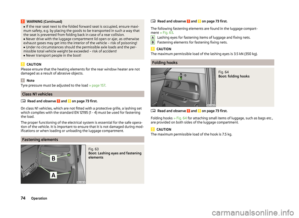
The following fastening elements are found in the luggage compart-
ment » Fig. 63 .
Lashing eyes for fastening items of luggage and fixing nets.
Fastening elements for fastening fixing nets.
CAUTION
The maximum permissible load of the lashing eyes is 3.5 kN (350 kg).
Folding hooks
Fig. 64
Boot: folding hooks
Read and observe and on page 73 first.
Folding hooks » Fig. 64 for attaching small items of luggage, such as bags etc.,
are provided on both sides of the luggage compartment.
CAUTION
The maximum permissible load of the hook is 7.5 kg.AB74Operation
Page 78 of 204

Fixing netsFig. 65
Fixing net: double horizontal pocket, floor fixing net/double verti-
cal pockets
Read and observe
and on page 73 first.
Fixing examples of the fixing net as a double horizontal pocket, floor fixing
net » Fig. 65 -
and double vertical pockets
» Fig. 65 -
.
WARNINGDo not exceed the maximum permissible load of the fixing nets. Heavy ob-
jects are not secured sufficiently – risk of injury!
CAUTION
■ The maximum permissible load of the fixing nets is 1.5 kg.■Do not place any sharp objects in the nets – risk of net damage.
Fixing floor covering of the luggage compartment
Read and observe
and on page 73 first.
You can fix the raised floor cover between the backrests and the luggage com-partment cover, if one needs to reach the spare wheel.
Boot coverFig. 66
Removing the luggage compartment cover/luggage compartment
cover in the lower position
Read and observe
and on page 73 first.
The boot cover can be removed if you wish to transport bulky goods.
›
Unhook support straps
1
» Fig. 66 .
›
Fold the luggage compartment cover forwards a little.
›
Remove the cover from the holders
2
by pulling towards the rear, or by
lightly knocking on the underside of the cover in the area between the hold-
ers.
›
To reinstall, first of all push the luggage compartment cover into the holders
2
and then hook the support straps
1
on the boot lid.
The luggage compartment cover can also be fitted in the lower position on the
supporting elements » Fig. 66 -
.
In this position you can store smaller objects up on the luggage compartment
cover up to a total weight of 2.5 kg.
WARNINGNo objects should be placed on the boot cover, the vehicle occupants could
be endangered if there is sudden braking or the vehicle collides with some-
thing.
CAUTION
Please ensure that the heating elements for the rear window heater are not
damaged as a result of objects placed in this area. 75Seats and stowing
Page 79 of 204
NoteWhen opening the boot lid, the luggage compartment cover is lifted up at the
same time- risk that objects placed in this area can slip forward!
Net partition
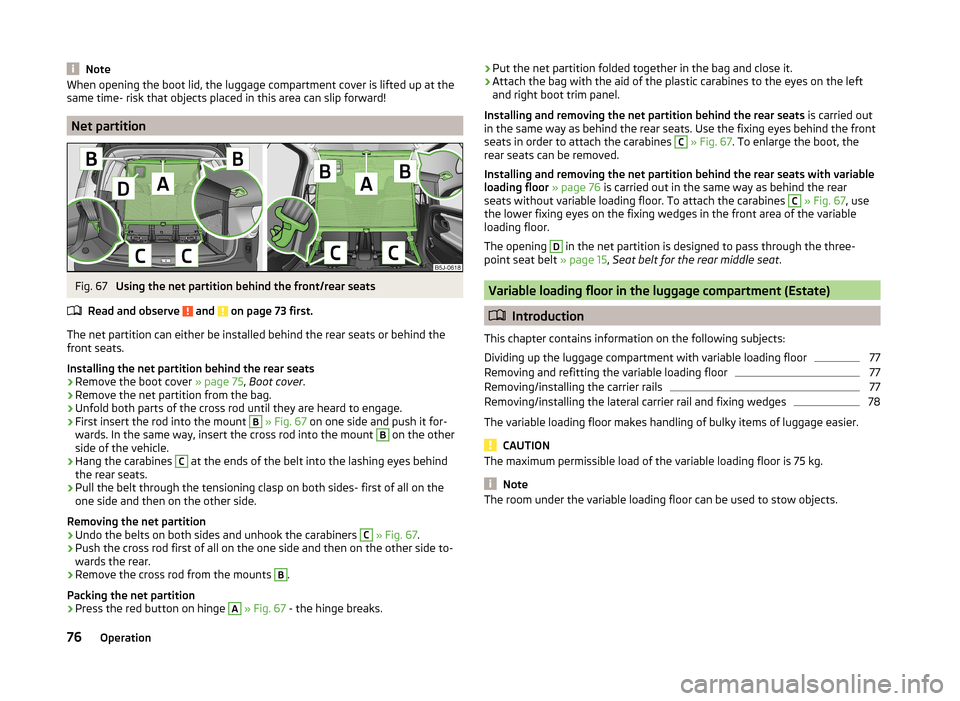
Fig. 67
Using the net partition behind the front/rear seats
Read and observe
and on page 73 first.
The net partition can either be installed behind the rear seats or behind the front seats.
Installing the net partition behind the rear seats
›
Remove the boot cover » page 75, Boot cover .
›
Remove the net partition from the bag.
›
Unfold both parts of the cross rod until they are heard to engage.
›
First insert the rod into the mount
B
» Fig. 67 on one side and push it for-
wards. In the same way, insert the cross rod into the mount
B
on the other
side of the vehicle.
›
Hang the carabines
C
at the ends of the belt into the lashing eyes behind
the rear seats.
›
Pull the belt through the tensioning clasp on both sides- first of all on the
one side and then on the other side.
Removing the net partition
›
Undo the belts on both sides and unhook the carabiners
C
» Fig. 67 .
›
Push the cross rod first of all on the one side and then on the other side to-
wards the rear.
›
Remove the cross rod from the mounts
B
.
Packing the net partition
›
Press the red button on hinge
A
» Fig. 67 - the hinge breaks.
›Put the net partition folded together in the bag and close it.›Attach the bag with the aid of the plastic carabines to the eyes on the left
and right boot trim panel.
Installing and removing the net partition behind the rear seats is carried out
in the same way as behind the rear seats. Use the fixing eyes behind the front
seats in order to attach the carabines C
» Fig. 67 . To enlarge the boot, the
rear seats can be removed.
Installing and removing the net partition behind the rear seats with variable
loading floor » page 76 is carried out in the same way as behind the rear
seats without variable loading floor. To attach the carabines
C
» Fig. 67 , use
the lower fixing eyes on the fixing wedges in the front area of the variable
loading floor.
The opening
D
in the net partition is designed to pass through the three-
point seat belt » page 15, Seat belt for the rear middle seat .
Variable loading floor in the luggage compartment (Estate)
Introduction
This chapter contains information on the following subjects:
Dividing up the luggage compartment with variable loading floor
77
Removing and refitting the variable loading floor
77
Removing/installing the carrier rails
77
Removing/installing the lateral carrier rail and fixing wedges
78
The variable loading floor makes handling of bulky items of luggage easier.
CAUTION
The maximum permissible load of the variable loading floor is 75 kg.
Note
The room under the variable loading floor can be used to stow objects.76Operation