boot SKODA ROOMSTER 2014 1.G Owner's Guide
[x] Cancel search | Manufacturer: SKODA, Model Year: 2014, Model line: ROOMSTER, Model: SKODA ROOMSTER 2014 1.GPages: 204, PDF Size: 14.15 MB
Page 80 of 204
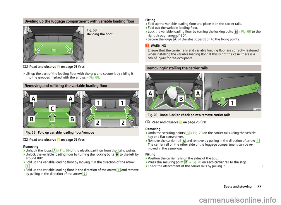
Dividing up the luggage compartment with variable loading floorFig. 68
Dividing the boot
Read and observe on page 76 first.
›
Lift up the part of the loading floor with the grip and secure it by sliding it
into the grooves marked with the arrows » Fig. 68.
Removing and refitting the variable loading floor
Fig. 69
Fold up variable loading floor/remove
Read and observe
on page 76 first.
Removing
›
Unhook the loops
A
» Fig. 69 of the elastic partition from the fixing points.
›
Unlock the variable loading floor by turning the locking bolts
B
to the left by
around 180°.
›
Fold up the variable loading floor by moving it in the direction of the arrow
C
.
›
Fold up the variable loading floor in the direction of the arrow
1
and remove
by pulling in the direction of the arrow
2
.
Fitting›Fold up the variable loading floor and place it on the carrier rails.›
Fold out the variable loading floor.
›
Lock the variable loading floor by turning the locking bolts
B
» Fig. 69 to the
right through around 180°.
›
Secure the loops
A
of the elastic partition to the fixing points.
WARNINGEnsure that the carrier rails and variable loading floor are correctly fastened
when installing the variable loading floor. If this is not the case, there is a
risk of injury for the occupants.
Removing/installing the carrier rails
Fig. 70
Boot: Slacken check points/remove carrier rails
Read and observe
on page 76 first.
Removing
›
Undo the securing points
B
» Fig. 70 on the carrier rails using the vehicle
key or a flat screwdriver.
›
Remove the carrier rail
A
and remove by pulling in the direction of arrow
1
.
The carrier rail on the other side of the luggage compartment can be re-
moved in the same way.
Fitting
›
Position the carrier rails on the sides of the boot.
›
Press the securing point
B
» Fig. 70 on each carrier rail to the stop.
›
Check the attachment of the carrier rails by pulling it.
77Seats and stowing
Page 81 of 204
WARNINGEnsure that the carrier rails and variable loading floor are correctly fastened
when installing the variable loading floor. If this is not the case, there is a
risk of injury for the occupants.
Removing/installing the lateral carrier rail and fixing wedges
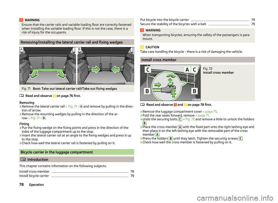
Fig. 71
Boot: Take out lateral carrier rail/Take out fixing wedges
Read and observe
on page 76 first.
Removing
›
Remove the lateral carrier rail » Fig. 71 -
and remove by pulling in the direc-
tion of arrow.
›
Remove the mounting wedges by pulling in the direction of the ar-
row » Fig. 71 -
.
Fitting
›
Put the fixing wedge on the fixing points and press in the direction of the
sides of the luggage compartment up to the stop.
›
Insert the lateral carrier rail at an angle to the fixing wedges and press it up
to the stop.
›
Check how well the lateral carrier rail is fastened by pulling on it.
Bicycle carrier in the luggage compartment
Introduction
This chapter contains information on the following subjects:
Install cross member
78
Install bicycle carrier
79Put bicycle into the bicycle carrier79Secure the stability of the bicycles with a belt79WARNINGWhen transporting bicycles, ensuring the safety of the passengers is para-
mount.
CAUTION
Take care handling the bicycle - there is a risk of damaging the vehicle.
Install cross member
Fig. 72
Install cross member
Read and observe and on page 78 first.
›
Remove the luggage compartment cover » page 75.
›
Fold the rear seats forward, remove » page 71.
›
Undo the securing bolts
C
» Fig. 72 and remove a little to unlock the holders
B
.
›
Place the cross member
A
with the fixed part onto the right lashing eye and
then place it on the left lashing eye with the removable part of the cross
member
A
.
›
Press the holders
B
until they latch. Tighten the securing screws
C
.
›
Check how well the cross member is fastened by pulling on it.
78Operation
Page 82 of 204
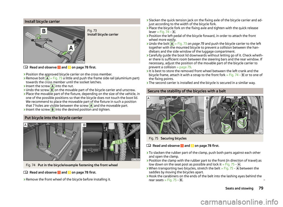
Install bicycle carrierFig. 73
Install bicycle carrier
Read and observe and on page 78 first.
›
Position the approved bicycle carrier on the cross member.
›
Remove bolt
A
» Fig. 73 a little and push the frame side rail (aluminium part)
towards the cross member until the socket latches.
›
Insert the screw
A
into the nut.
›
Undo the screw
B
on the movable part of the bicycle carrier and unscrew.
›
Place the movable part of the fixture, depending on the size of the vehicle, in
one of the possible positions so that the bicycle does not touch the boot lid.
We recommend to place the moveable part of the fixture in such a position
that 7 holes are visible between the screw
A
and the moveable part.
›
Insert the screw
B
into the desired position and tighten.
Put bicycle into the bicycle carrier
Fig. 74
Put in the bicycle/example fastening the front wheel
Read and observe
and on page 78 first.
›
Remove the front wheel of the bicycle before installing it.
› Slacken the quick tension jack on the fixing axle of the bicycle carrier and ad-
just according to the width of the bicycle fork.›
Place the bicycle fork on the fixing axle and tighten with the quick release
lever » Fig. 74 -
.
›
Position the left pedal of the bicycle forward, in order to attach the front
wheel more easily.
›
Undo the bolt
A
» Fig. 73 on page 79 and push the bicycle carrier to the left
together with the mounted bicycle to prevent a collision between the han-
dlebars and the side window of the luggage compartment.
›
Carefully guide the boot lid downwards without letting go of it. Check wheth-
er there is sufficient room between the steering bars and the rear window. If
necessary, adjust the position of the movable part of the bicycle carrier to
prevent a collision » page 79.
›
It is best to store the removed front wheel between the left crank and the
bicycle frame, attach it with a strap to the front fork » Fig. 74 -
or to one of
the fixing points.
›
The second carrier is installed and the bicycle is secured in a similar way.
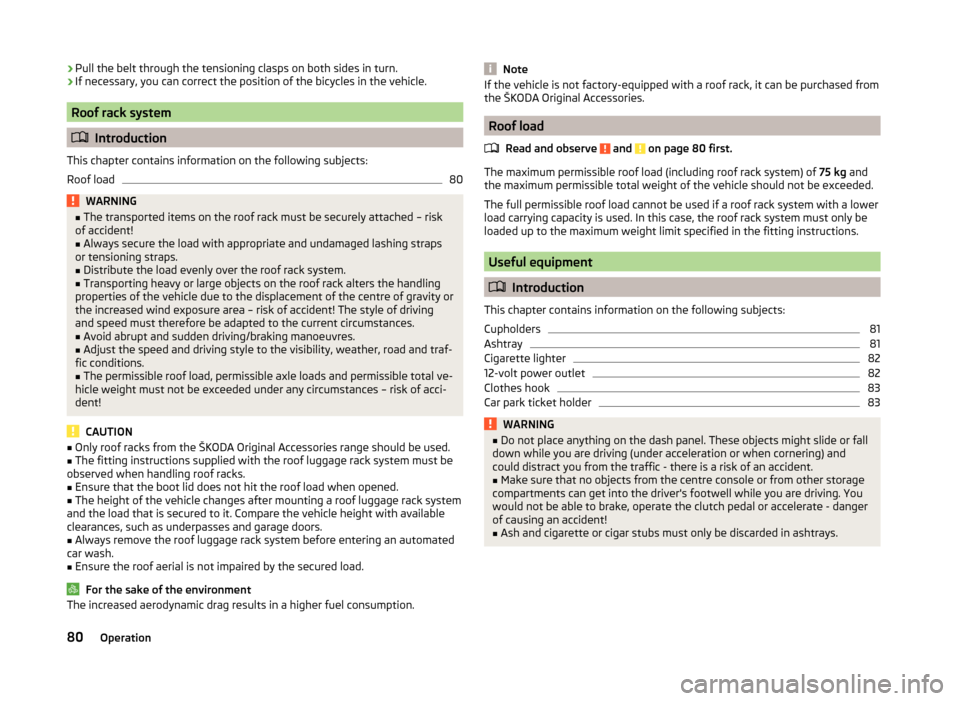
Secure the stability of the bicycles with a belt
Fig. 75
Securing bicycles
Read and observe
and on page 78 first.
›
To slacken the rubber part of the clamp, push both parts against each other
and open the clamp.
›
Position the clamp with the rubber part to the front (in direction of travel) as
low down on the seat post as possible and lock it » Fig. 75 -
.
›
When transporting two bicycles, stretch the belt
» Fig. 75 -
between the
saddles by moving the bicycles apart.
›
Hook the carabiners on the ends of the belt into the lashing eyes behind the
rear seats » Fig. 75 -
.
79Seats and stowing
Page 83 of 204
›Pull the belt through the tensioning clasps on both sides in turn.›If necessary, you can correct the position of the bicycles in the vehicle.
Roof rack system
Introduction
This chapter contains information on the following subjects:
Roof load
80WARNING■ The transported items on the roof rack must be securely attached – risk
of accident!■
Always secure the load with appropriate and undamaged lashing straps
or tensioning straps.
■
Distribute the load evenly over the roof rack system.
■
Transporting heavy or large objects on the roof rack alters the handling
properties of the vehicle due to the displacement of the centre of gravity or
the increased wind exposure area – risk of accident! The style of driving
and speed must therefore be adapted to the current circumstances.
■
Avoid abrupt and sudden driving/braking manoeuvres.
■
Adjust the speed and driving style to the visibility, weather, road and traf-
fic conditions.
■
The permissible roof load, permissible axle loads and permissible total ve-
hicle weight must not be exceeded under any circumstances – risk of acci-
dent!
CAUTION
■ Only roof racks from the ŠKODA Original Accessories range should be used.■The fitting instructions supplied with the roof luggage rack system must be
observed when handling roof racks.■
Ensure that the boot lid does not hit the roof load when opened.
■
The height of the vehicle changes after mounting a roof luggage rack system
and the load that is secured to it. Compare the vehicle height with available
clearances, such as underpasses and garage doors.
■
Always remove the roof luggage rack system before entering an automated
car wash.
■
Ensure the roof aerial is not impaired by the secured load.
For the sake of the environment
The increased aerodynamic drag results in a higher fuel consumption.NoteIf the vehicle is not factory-equipped with a roof rack, it can be purchased from
the ŠKODA Original Accessories.
Roof load
Read and observe
and on page 80 first.
The maximum permissible roof load (including roof rack system) of 75 kg and
the maximum permissible total weight of the vehicle should not be exceeded.
The full permissible roof load cannot be used if a roof rack system with a lower
load carrying capacity is used. In this case, the roof rack system must only be
loaded up to the maximum weight limit specified in the fitting instructions.
Useful equipment
Introduction
This chapter contains information on the following subjects:
Cupholders
81
Ashtray
81
Cigarette lighter
82
12-volt power outlet
82
Clothes hook
83
Car park ticket holder
83WARNING■ Do not place anything on the dash panel. These objects might slide or fall
down while you are driving (under acceleration or when cornering) and
could distract you from the traffic - there is a risk of an accident.■
Make sure that no objects from the centre console or from other storage
compartments can get into the driver's footwell while you are driving. You
would not be able to brake, operate the clutch pedal or accelerate - danger
of causing an accident!
■
Ash and cigarette or cigar stubs must only be discarded in ashtrays.
80Operation
Page 85 of 204
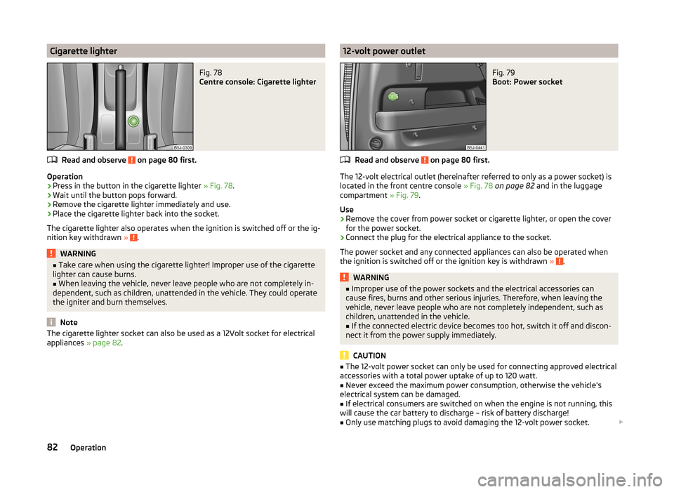
Cigarette lighterFig. 78
Centre console: Cigarette lighter
Read and observe on page 80 first.
Operation
›
Press in the button in the cigarette lighter » Fig. 78.
›
Wait until the button pops forward.
›
Remove the cigarette lighter immediately and use.
›
Place the cigarette lighter back into the socket.
The cigarette lighter also operates when the ignition is switched off or the ig-
nition key withdrawn »
.
WARNING■
Take care when using the cigarette lighter! Improper use of the cigarette
lighter can cause burns.■
When leaving the vehicle, never leave people who are not completely in-
dependent, such as children, unattended in the vehicle. They could operate
the igniter and burn themselves.
Note
The cigarette lighter socket can also be used as a 12Volt socket for electrical
appliances » page 82.12-volt power outletFig. 79
Boot: Power socket
Read and observe on page 80 first.
The 12-volt electrical outlet (hereinafter referred to only as a power socket) is
located in the front centre console » Fig. 78 on page 82 and in the luggage
compartment » Fig. 79.
Use
›
Remove the cover from power socket or cigarette lighter, or open the cover
for the power socket.
›
Connect the plug for the electrical appliance to the socket.
The power socket and any connected appliances can also be operated when
the ignition is switched off or the ignition key is withdrawn »
.
WARNING■
Improper use of the power sockets and the electrical accessories can
cause fires, burns and other serious injuries. Therefore, when leaving the
vehicle, never leave people who are not completely independent, such as
children, unattended in the vehicle.■
If the connected electric device becomes too hot, switch it off and discon-
nect it from the power supply immediately.
CAUTION
■ The 12-volt power socket can only be used for connecting approved electrical
accessories with a total power uptake of up to 120 watt.■
Never exceed the maximum power consumption, otherwise the vehicle's
electrical system can be damaged.
■
If electrical consumers are switched on when the engine is not running, this
will cause the car battery to discharge – risk of battery discharge!
■
Only use matching plugs to avoid damaging the 12-volt power socket.
82Operation
Page 90 of 204
WARNINGUse the section A » Fig. 90 of the door pocket only for storing objects
which do not project so that the effectiveness of the side airbag is not im-
paired.
stowage compartments in the luggage
Fig. 91
Storage compartments in the
side trim panel
Read and observe on page 83 first.
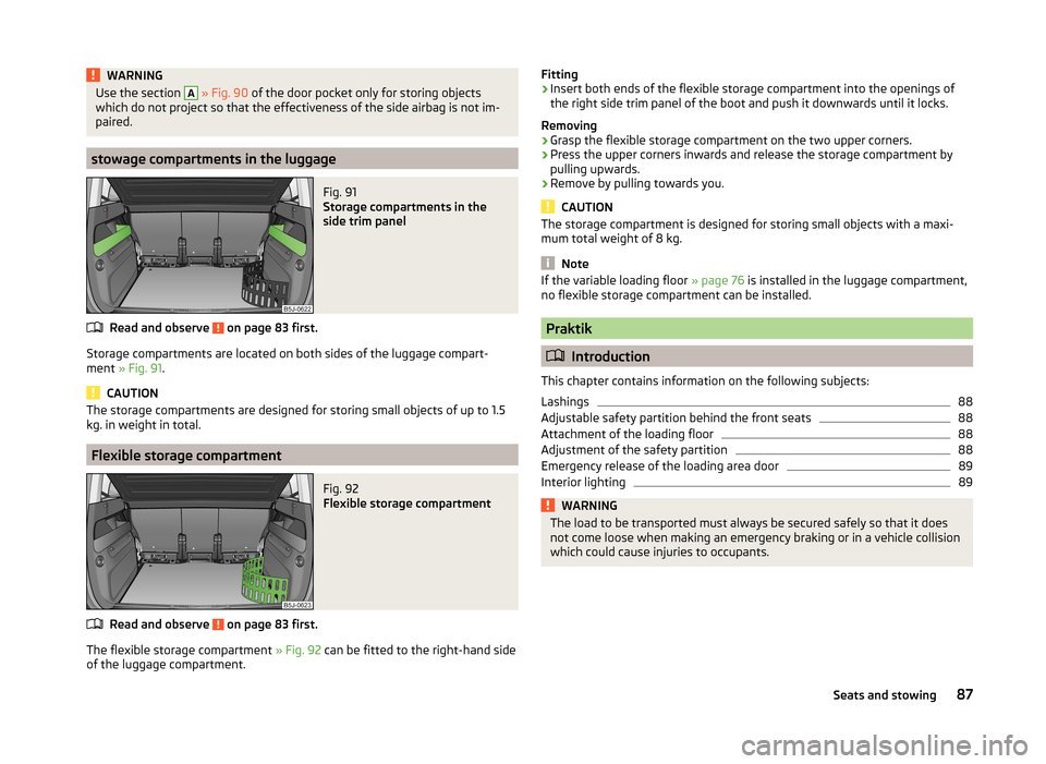
Storage compartments are located on both sides of the luggage compart-
ment » Fig. 91 .
CAUTION
The storage compartments are designed for storing small objects of up to 1.5
kg. in weight in total.
Flexible storage compartment
Fig. 92
Flexible storage compartment
Read and observe on page 83 first.
The flexible storage compartment » Fig. 92 can be fitted to the right-hand side
of the luggage compartment.
Fitting›Insert both ends of the flexible storage compartment into the openings of
the right side trim panel of the boot and push it downwards until it locks.
Removing›
Grasp the flexible storage compartment on the two upper corners.
›
Press the upper corners inwards and release the storage compartment by
pulling upwards.
›
Remove by pulling towards you.
CAUTION
The storage compartment is designed for storing small objects with a maxi-
mum total weight of 8 kg.
Note
If the variable loading floor » page 76 is installed in the luggage compartment,
no flexible storage compartment can be installed.
Praktik
Introduction
This chapter contains information on the following subjects:
Lashings
88
Adjustable safety partition behind the front seats
88
Attachment of the loading floor
88
Adjustment of the safety partition
88
Emergency release of the loading area door
89
Interior lighting
89WARNINGThe load to be transported must always be secured safely so that it does
not come loose when making an emergency braking or in a vehicle collision
which could cause injuries to occupants.87Seats and stowing
Page 91 of 204
LashingsFig. 93
Loading area: Lashing eyes
Read and observe on page 87 first.
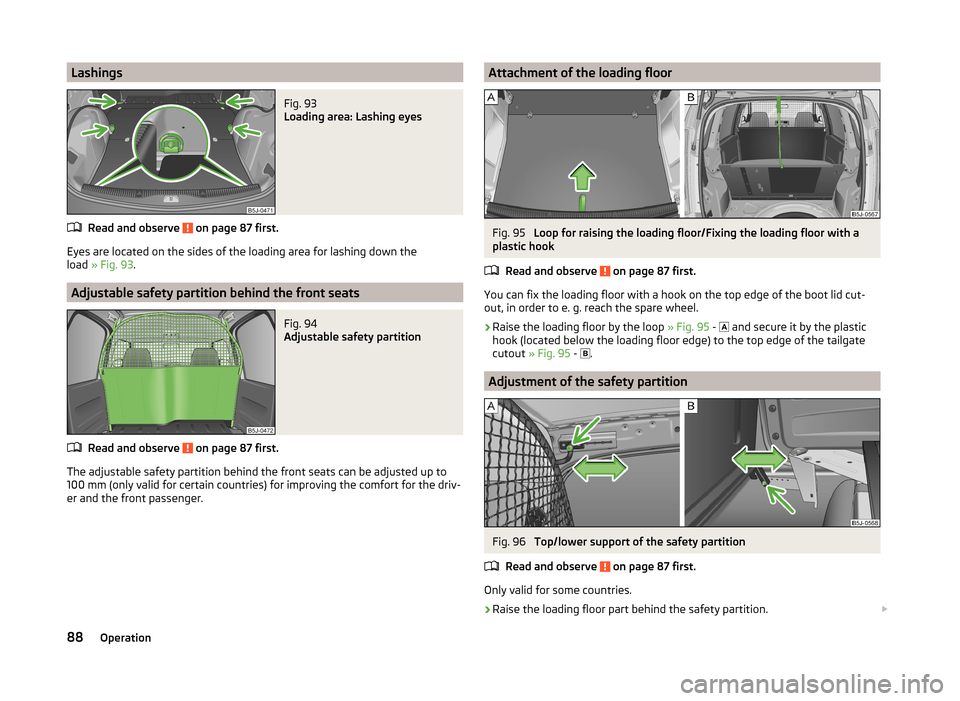
Eyes are located on the sides of the loading area for lashing down the
load » Fig. 93 .
Adjustable safety partition behind the front seats
Fig. 94
Adjustable safety partition
Read and observe on page 87 first.
The adjustable safety partition behind the front seats can be adjusted up to
100 mm (only valid for certain countries) for improving the comfort for the driv-
er and the front passenger.
Attachment of the loading floorFig. 95
Loop for raising the loading floor/Fixing the loading floor with a
plastic hook
Read and observe
on page 87 first.
You can fix the loading floor with a hook on the top edge of the boot lid cut-
out, in order to e. g. reach the spare wheel.
›
Raise the loading floor by the loop » Fig. 95 -
and secure it by the plastic
hook (located below the loading floor edge) to the top edge of the tailgate
cutout » Fig. 95 -
.
Adjustment of the safety partition
Fig. 96
Top/lower support of the safety partition
Read and observe
on page 87 first.
Only valid for some countries.
›
Raise the loading floor part behind the safety partition.
88Operation
Page 132 of 204
WARNING■Never allow the ball head to remain unsecured in the boot. This could
cause damage to the boot upon sudden braking, and could put the safety
of the occupants at risk.■
Never remove the tow bar while the trailer is still coupled.
CAUTION
■ If the lever is held firmly and not pushed downwards as far as it can go, it will
go back up after the ball head is removed and will not latch into the ready po-
sition. The ball head then needs to be brought into this position before the
next time it is fitted » page 127, Adjusting the ready position .■
Tuck the ball bar in the ready position, with the golden key up, in the box -
otherwise there is a risk of damage to the key!
■
Do not use excessive force when handling the operating lever (e.g. do not
step on it).
Note
■ We recommend that you put the protective cap on the ball before removing
the ball head.■
Clean any dirt from the ball head before stowing it away in the box with the
vehicle tool kit.
Accessories
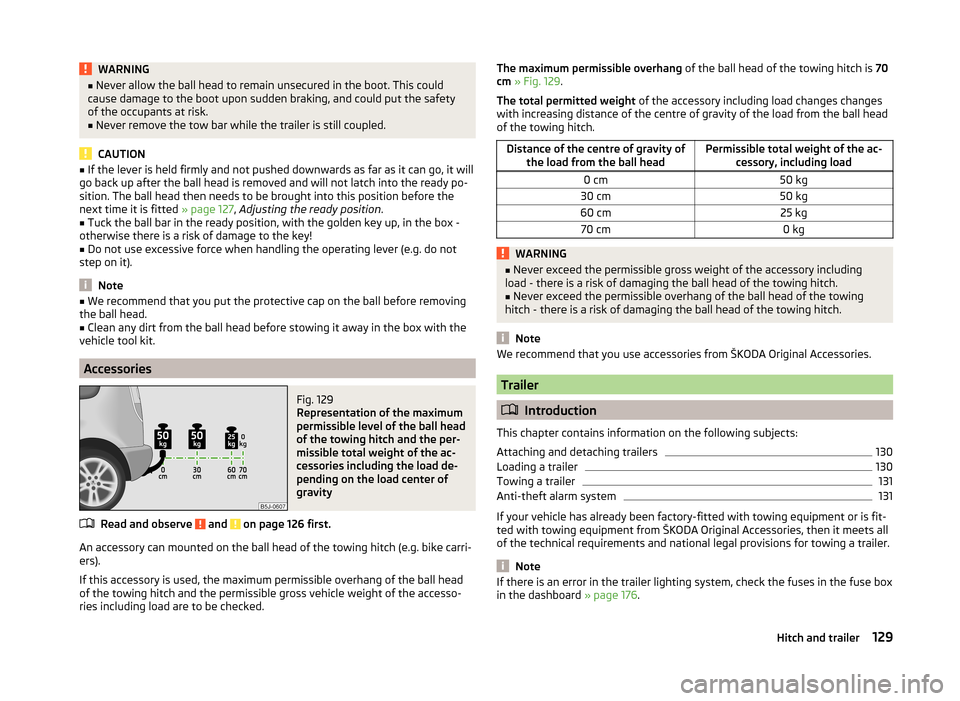
Fig. 129
Representation of the maximum
permissible level of the ball head
of the towing hitch and the per-
missible total weight of the ac-
cessories including the load de-
pending on the load center of
gravity
Read and observe and on page 126 first.
An accessory can mounted on the ball head of the towing hitch (e.g. bike carri- ers).
If this accessory is used, the maximum permissible overhang of the ball head
of the towing hitch and the permissible gross vehicle weight of the accesso-
ries including load are to be checked.
The maximum permissible overhang of the ball head of the towing hitch is 70
cm » Fig. 129 .
The total permitted weight of the accessory including load changes changes
with increasing distance of the centre of gravity of the load from the ball head
of the towing hitch.Distance of the centre of gravity of the load from the ball headPermissible total weight of the ac- cessory, including load0 cm50 kg30 cm50 kg60 cm25 kg70 cm0 kgWARNING■Never exceed the permissible gross weight of the accessory including
load - there is a risk of damaging the ball head of the towing hitch.■
Never exceed the permissible overhang of the ball head of the towing
hitch - there is a risk of damaging the ball head of the towing hitch.
Note
We recommend that you use accessories from ŠKODA Original Accessories.
Trailer
Introduction
This chapter contains information on the following subjects:
Attaching and detaching trailers
130
Loading a trailer
130
Towing a trailer
131
Anti-theft alarm system
131
If your vehicle has already been factory-fitted with towing equipment or is fit-
ted with towing equipment from ŠKODA Original Accessories, then it meets all
of the technical requirements and national legal provisions for towing a trailer.
Note
If there is an error in the trailer lighting system, check the fuses in the fuse box
in the dashboard » page 176.129Hitch and trailer
Page 144 of 204
Synthetic leather, fabrics and Alcantara®
Read and observe
and on page 139 first.
Artificial leather
Clean artificial leather with a damp cloth.
If this method does not completely clean the artificial leather, use a mild soap
solution or cleaning products specially designed for this purpose.
Fabric
Clean upholstery cover materials and cloth trims on doors, boot cover, etc. us-
ing specific cleaning agents, e.g., dry foam.
Use a soft sponge, brush, or commercially available microfibre cloth.
Use a cloth and special detergent to clean the headlining.
Remove any lumps on the cover fabric and any fabric residue using a brush.
Remove stubborn hair using a “cleaning glove”.
Alcantara ®
Dust and fine dirt particles in pores, creases and seams may chafe and damage
the surface.
If you leave your vehicle parked in the open for lengthy periods, protect the Al-
cantara ®
seat upholstery from direct sunlight to prevent fading.
Minor changes in colour caused by use are normal.
CAUTION
■ Do not use leather cleaners on Alcantara ®
seat upholstery.■Do not use solvents, floor wax, shoe cream, stain remover or similar agents
on Alcantara ®
seat upholstery.■
Avoid leaving the vehicle in bright sunlight for long periods of time in order
to stop the fabric from bleaching. If the vehicle is parked outside for long peri-
ods of time, cover the fabric to protect it from direct sunlight.
■
Some clothing materials, e.g. dark denim, do not have sufficient colour fast-
ness. This can cause damage or clearly visible discolouration to seat covers,
even when used correctly. This applies particularly to light-coloured seat cov-
ers. This does not relate to a fault in the seat cover, but rather to poor colour
fastness of the clothing textiles.
Seat covers
Read and observe
and on page 139 first.
Electrically heated seats
Do not clean the covers by moistening, as this can damage the seat heating
system.
Use a specific cleaning agent such as dry foam or similar to clean the covers.
Seats without seat heating
Thoroughly vacuum the seat covers with a vacuum cleaner before cleaning.
Clean the seat covers with a damp cloth or cleaning products specially de-
signed for this purpose.
Indented points arising on the fabrics by everyday use, can be removed by
brushing against the direction of hair with a damp brush.
Always clean all parts of the covers, so that there are no visible edges. Then
allow the seat to dry completely.
CAUTION
■ Regularly remove dust from the seat covers using a vacuum cleaner.■Electrically heated seats must not be dried after cleaning by switching on the
heater.■
Do not sit on wet seats - risk of seat deformation.
■
Always clean the seats “from seam to seam”.
Seat belts
Read and observe
and on page 139 first.
The belt webbing must always be kept clean.
Wash dirty seat belts with mild soapy water.
Remove coarse dirt with a soft brush.
Dirty belt webbing may impair the correct functioning of the inertia reel.
WARNING■ The seat belts must not be removed for cleaning.■Never clean the seat belts chemically as chemical cleaning products could
destroy the fabric. 141Car care
Page 162 of 204
Spare and temporary spare wheelFig. 143
Fixing the spare or temporary
spare wheel
Read and observe and on page 156 first.
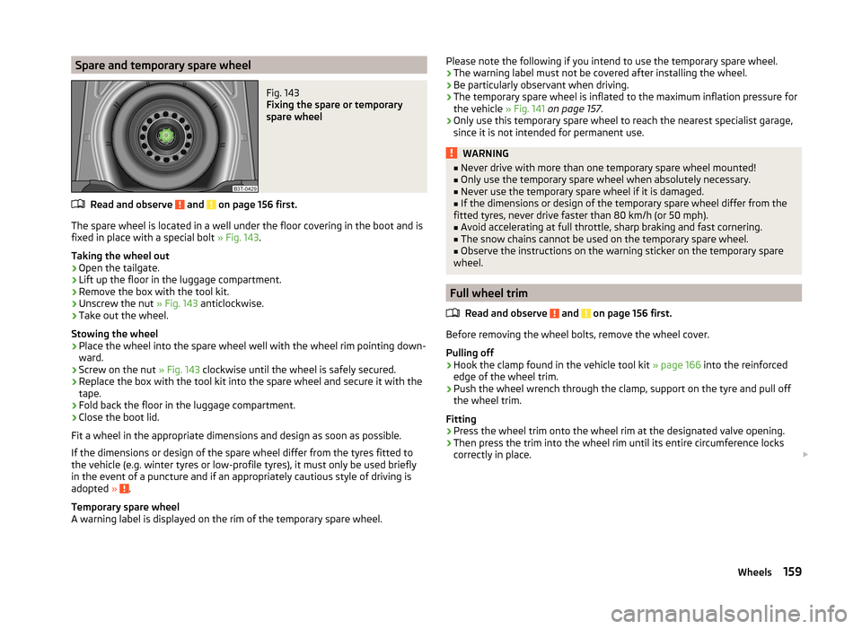
The spare wheel is located in a well under the floor covering in the boot and is
fixed in place with a special bolt » Fig. 143.
Taking the wheel out
›
Open the tailgate.
›
Lift up the floor in the luggage compartment.
›
Remove the box with the tool kit.
›
Unscrew the nut » Fig. 143 anticlockwise.
›
Take out the wheel.
Stowing the wheel
›
Place the wheel into the spare wheel well with the wheel rim pointing down-
ward.
›
Screw on the nut » Fig. 143 clockwise until the wheel is safely secured.
›
Replace the box with the tool kit into the spare wheel and secure it with the
tape.
›
Fold back the floor in the luggage compartment.
›
Close the boot lid.
Fit a wheel in the appropriate dimensions and design as soon as possible.
If the dimensions or design of the spare wheel differ from the tyres fitted to
the vehicle (e.g. winter tyres or low-profile tyres), it must only be used briefly
in the event of a puncture and if an appropriately cautious style of driving is
adopted »
.
Temporary spare wheel
A warning label is displayed on the rim of the temporary spare wheel.
Please note the following if you intend to use the temporary spare wheel.
› The warning label must not be covered after installing the wheel.
› Be particularly observant when driving.
› The temporary spare wheel is inflated to the maximum inflation pressure for
the vehicle » Fig. 141 on page 157 .
› Only use this temporary spare wheel to reach the nearest specialist garage,
since it is not intended for permanent use.WARNING■ Never drive with more than one temporary spare wheel mounted!■Only use the temporary spare wheel when absolutely necessary.■
Never use the temporary spare wheel if it is damaged.
■
If the dimensions or design of the temporary spare wheel differ from the
fitted tyres, never drive faster than 80 km/h (or 50 mph).
■
Avoid accelerating at full throttle, sharp braking and fast cornering.
■
The snow chains cannot be used on the temporary spare wheel.
■
Observe the instructions on the warning sticker on the temporary spare
wheel.
Full wheel trim
Read and observe
and on page 156 first.
Before removing the wheel bolts, remove the wheel cover.
Pulling off
›
Hook the clamp found in the vehicle tool kit » page 166 into the reinforced
edge of the wheel trim.
›
Push the wheel wrench through the clamp, support on the tyre and pull off
the wheel trim.
Fitting
›
Press the wheel trim onto the wheel rim at the designated valve opening.
›
Then press the trim into the wheel rim until its entire circumference locks
correctly in place.
159Wheels