technical data SKODA SUPERB 2003 1.G / (B5/3U) Owner's Manual
[x] Cancel search | Manufacturer: SKODA, Model Year: 2003, Model line: SUPERB, Model: SKODA SUPERB 2003 1.G / (B5/3U)Pages: 259
Page 222 of 259

Wheels and Tyres221
Using the systemSafetyDriving TipsGeneral MaintenanceBreakdown assistanceTechnical Data
Wheel alignment errors
Incorrect wheel alignment at the front and rear will not only increase wear-
and-tear on the tyres but will also has an adverse effect on vehicle safety.
Contact your Škoda dealer if you notice any unusual tyre wear.
For the sake of
the environment
Tyres which are insufficiently inflated increase your fuel consumption.
Wear indicators
The base of the tread of the original tyres has wear indicators 1.6 mm
high, installed at right angles to the direction of travel. These wear indica-
tors are located at 6 to 8 points depending on the make and are evenly
spaced around the circumference of the tyre ⇒fig. 166 . Markings on the
walls of the tyres through the letters “TWI” or triangular symbols identify
the position of the wear indicators.
A remaining tread of just 1.6 mm, measured in the grooves of the tread
next to the wear indicators, means that your tyres have reached their
legally permissible minimum tread depth.
WARNING
If the inflation pressure is too low, the tyre must perform a greater
flexing work. At higher speeds the tyre will warm up as a result of
this. This can result in tread separation and even a tyre blowout.
Fig. 166 Tyre tread
with wear indicators
WARNING
•You must have your tyres replaced with new ones at the latest
when the wear indicators have been worn down. The legally
permissible minimum tread de pth should be observed.
•Worn tyres do not provide the necessary adhesion to the road
surface at high speeds on wet roads. One could experience “aqua-
planing” (uncontrolled movements of the vehicle - “swimming” on
a wet road surface).
Page 224 of 259

Wheels and Tyres223
Using the systemSafetyDriving TipsGeneral MaintenanceBreakdown assistanceTechnical Data
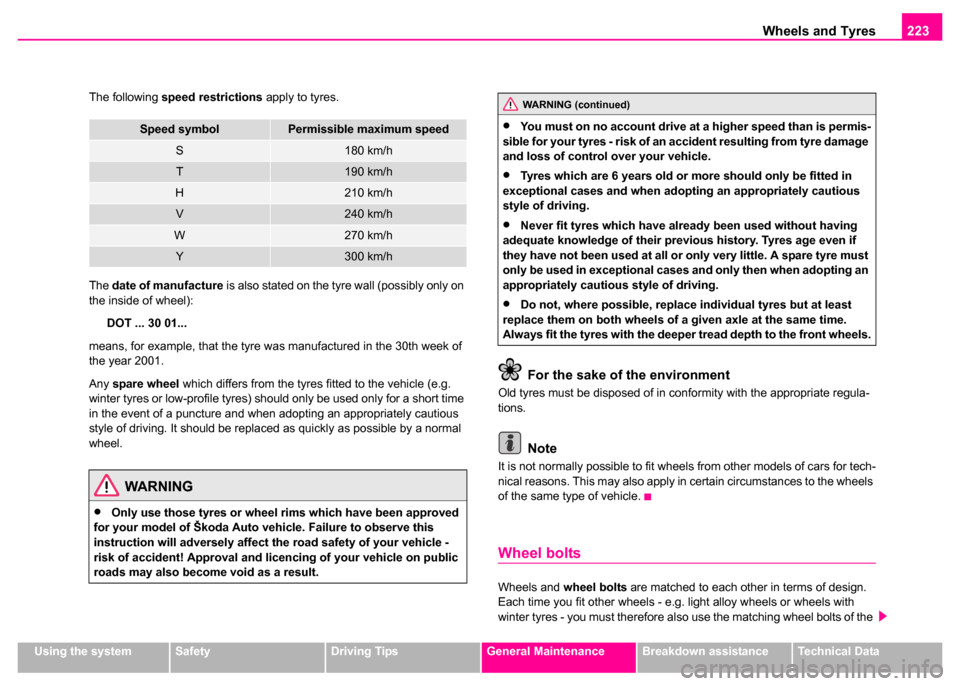
The following
speed restrictions apply to tyres.
The date of manufacture is also stated on the tyre wall (possibly only on
the inside of wheel):
DOT ... 30 01...
means, for example, that the tyre was manufactured in the 30th week of
the year 2001.
Any spare wheel which differs from the tyres fitted to the vehicle (e.g.
winter tyres or low-profile tyres) should only be used only for a short time
in the event of a puncture and when adopting an appropriately cautious
style of driving. It should be replaced as quickly as possible by a normal
wheel.
For the sake of the environment
Old tyres must be disposed of in conformity with the appropriate regula-
tions.
Note
It is not normally possible to fit wheels from other models of cars for tech-
nical reasons. This may also apply in certain circumstances to the wheels
of the same type of vehicle.
Wheel bolts
Wheels and wheel bolts are matched to each other in terms of design.
Each time you fit other wheels - e.g. light alloy wheels or wheels with
winter tyres - you must therefore also use the matching wheel bolts of the
Speed symbolPermissible maximum speed
S180 km/h
T190 km/h
H210 km/h
V240 km/h
W270 km/h
Y300 km/h
WARNING
•Only use those tyres or wheel rims which have been approved
for your model of Škoda Auto vehicle. Failure to observe this
instruction will adversely affect the road safety of your vehicle -
risk of accident! Approval and licencing of your vehicle on public
roads may also become void as a result.
WARNING (continued)
•You must on no account drive at a higher speed than is permis-
sible for your tyres - risk of an accident resulting from tyre damage
and loss of control over your vehicle.
•Tyres which are 6 years old or more should only be fitted in
exceptional cases and when adopting an appropriately cautious
style of driving.
•Never fit tyres which have already been used without having
adequate knowledge of their previous history. Tyres age even if
they have not been used at all or only very little. A spare tyre must
only be used in exceptional cases and only then when adopting an
appropriately cautious style of driving.
•Do not, where possible, replace individual tyres but at least
replace them on both wheels of a given axle at the same time.
Always fit the tyres with the deeper tread depth to the front wheels.
Page 226 of 259

Wheels and Tyres225
Using the systemSafetyDriving TipsGeneral MaintenanceBreakdown assistanceTechnical Data
Unidirectional tyres*
The direction of rotation of the tyres is marked by arrows on the wall of
the tyre . This indicates the direction of rotation of the tyre, and it is essen-
tial that the tyres are fitted on to run in this direction. Only then are the
tyres able to provide the optimal properties in terms of grip, low noise,
wear-and-tear and aquaplaning.
Should it be necessary to fit on a spare wheel in exceptional cases with a
tyre not dedicated to the running direction, please adopt a cautious style
of driving as the tyre is no longer able to provide optimal grip and handling
in such a situation. This particularly important on wet roads. Please refer
to the notes ⇒page 229.
You should have the defective tyre replaced as soon as possible and
restore the correct direction of rotation on all tyres
Snow chains
Snow chains can be used only for wheel sizes 6J x 16 ET 40 or 6J x 16
ET 37. Your Škoda Dealer can provide you with more detailed information.
Snow chains must only be mounted on the front wheels.
When driving on wintry roads, snow chains improve not only traction, but
also the braking performance.
Only use fine-link snow chains . They must not project more than 15 mm
- including the chain lock.
Remove the full wheel trim if you wish to fit snow chains to the wheels.
You must take the chains off as soon as you drive on roads which are free
of snow. They adversely affect the handling of your vehicle, damage the
tyres and are rapidly destroyed. Observe the national legal requirements relating to the maximum vehicle
speed with snow chains.
Note
We recommend that you use snow chains from the Škoda range of
genuine accessories.
Page 228 of 259

Breakdown assistance227
Using the systemSafetyDriving TipsGeneral MaintenanceBreakdown assistanceTechnical Data
Breakdown assistance
Breakdown assistance
First-aid box*
First-aid box
The compartment for stowing the first-aid box is located in the left of the
luggage compartment ⇒fig. 168 .
Note
Pay attention to the use-by-date of the contents of the first-aid box.
Warning triangle
– To remove the warning triangle, turn the rotary lock in direc-
tion of arrow ⇒fig. 169 and fold the fixture down.
Fig. 168 Compartment
for stowing first-aid
boxFig. 169 Warning
triangle fitted inside
boot lid
Page 230 of 259

Breakdown assistance229
Using the systemSafetyDriving TipsGeneral MaintenanceBreakdown assistanceTechnical Data
Spare wheel
The spare wheel is stowed in the spare wheel well in the
luggage compartment below the floor covering.
The spare wheel lies in a well under the luggage compartment floor and
is fixed in place using special screws ⇒fig. 172 . One should check the air pressure in the spare wheel (at best when
generally checking the tyre air pressures - see sign on the fuel filler flap)
to ensure that the spare wheel is always ready to use.
Unidirectional tyres*
If you have such tyres on your vehicle, please refer to the notes below:
•The spare wheel provided with a car fitted with unidirectional tyres has
different dimensions. The wheel is provided with a warning sticker.
•After fitting on the wheel, the warning sticker must not be concealed
(e.g. by the wheel trim).
•Do not drive with this spare wheel at more than 80 km/h - risk of acci-
dent. Avoid accelerating at full throttle, sharp braking and fast cornering.
•The inflation pressure for this spare wheel is identical to the inflation
pressure of the standard tyres.
•Use this spare wheel only to reach the nearest service station as it is
not intended for continuous use.
Changing a wheel
Preliminary work
The following steps should be carried out before actually
changing the wheel.
– If it is necessary to change a wheel, park the vehicle as far away as possible from the traffic flow. The place you choose
should be level.
WARNING
•The hexagon socket in the handle of the screwdriver is used for
fitting on the wheel bolts. Neve r use it for tightening the wheel
bolts because you will not be able to achieve the necessary tight-
ening torque with this tool - risk of accident!
•The factory-supplied lifting jack is only intended for your model
of vehicle. On no account attempt to lift a heavier vehicle or other
loads - risk of injury!
Fig. 172 Luggage
compartment: Spare
wheel
Page 232 of 259

Breakdown assistance231
Using the systemSafetyDriving TipsGeneral MaintenanceBreakdown assistanceTechnical Data
Subsequent steps
After changing the wheel, you must perform the following steps.
– Stow and attach the replaced wheel in the spare wheel well.
– Stow the vehicle tool kit in the space provided.
–Check the tyre pressure on the spare wheel just mounted as
soon as possible.
– Have the tightening torque of the wheel bolts checked with
a torque wrench as soon as possible. The tightening torque
must be 120 Nm.
– Have the defective tyre repaired as soon as possible.
Note
•If you find, when changing the wheel, that the wheel bolts are corroded
and difficult to turn, the bolts must be replaced before checking the tight-
ening torque.
•Drive cautiously and only at a moderate speed to a workshop where
the tightening torque can be checked.
Full wheel trim*
Removing
– Hook the clamp (found in the vehicle toolkit) into the reinforced edge of the full wheel trim.
– Push the wheel key through the clamp, support the wheel key at the tyre and pull off the wheel trim.
Installing
– First press the full wheel trim onto the wheel at the valve opening provided. Then press the full wheel trim into the
wheel in such a way that its entire circumference locks
correctly in place.
Caution
Use the pressure of your hand, do not knock on the full wheel trim! Heavy
knocks mainly on the points where the full wheel trim has not been
inserted into the wheel, can result in damage to the guide and centering
elements of the full wheel trim.WARNING
It is necessary to observe the guidelines given on ⇒page 222,
“New tyres and wheels” if the vehicle is subsequently fitted with
tyres which are different to those it was fitted with at the works.
Page 234 of 259

Breakdown assistance233
Using the systemSafetyDriving TipsGeneral MaintenanceBreakdown assistanceTechnical Data
Slackening and tightening wheel bolts
Slacken the wheel bolts before jacking up the vehicle.
Slackening wheel bolts
– Push the wheel wrench fully onto the wheel bolt
3).
– Grasp the end of the wrench and turn the bolt about one turn to the left ⇒fig. 175.
Tightening wheel bolts
– Push the wheel wrench fully onto the wheel bolt
3).
– Grasp the end of the wrench and turn the bolt to the right until it is tight. Note
•Do not use the hexagon socket in the handle of the screwdriver for
slackening or tightening the wheel bolts.
•apply pressure carefully with your foot to the end of the wheel wrench
if it proves difficult to slacken the wheel bolts. Hold tight on the vehicle
when doing this and ensure that you have a steady position.
Raise vehicle
You have to raise the vehicle with a lifting jack in order to
be able to take off the wheel.
3)Use the appropriate adapter for slackening and tightening the safety wheel bolts
⇒ page 235.
Fig. 175 Changing a
wheel: Slackening
wheel bolts
WARNING
Slacken the wheel bolts only a little (about one turn) as long as the
vehicle has not yet been jacked up - risk of an accident!.
Fig. 176 Changing a
wheel: Points for posi-
tioning car jack
Page 236 of 259

Breakdown assistance235
Using the systemSafetyDriving TipsGeneral MaintenanceBreakdown assistanceTechnical Data
Changing a wheel
– Turn the wheel bolt which is farthest to the top fully out with
the hexagon socket in the screwdriver handle (car tool kit)
and place the bolt down on a clean surface ⇒page 234,
fig. 177 .
– Screw the assembly pin (car tool kit) into the vacant hole ⇒page 234, fig. 178.
– Unscrew the remaining wheel bolts as described above.
– Take off the wheel.
Fitting on wheel
– Push the spare wheel over the assembly pin.
– Screw in the wheel bolts and tighten them slightly with the aid
of the hexagon socket.
– Unscrew the assembly pin and screw in the remaining wheel bolt also slightly.
The wheel bolts must be clean and must turn easily.
The hexagon socket in the handle of the screwdriver makes it simpler to
fit on the wheel bolts. The reversible blade should be pulled out for this
step.
When fitting on unidirectional tyres, ensure that the tyres rotate in the
correct direction ⇒page 225.
Note
Do not use the hexagon socket in the handle of the screwdriver for slack-
ening or tightening the wheel bolts.
Securing wheels against being stolen
You need a special adapter for slackening the safety
wheel bolts.
– Pull off the full wheel trim/cap from the wheel hub or cap from
the safety wheel bolt.
– Push the adapter with its toothed side into the inner toothing of the safety wheel bolt right down in such a way
that only the outer hexagon is jutting out ⇒fig. 179.
– Push the wheel wrench fully onto the adapter .
– Slacken the wheel bolt, or tighten it firmly ⇒page 223.
– Reinstall the full wheel trim/wheel cap after removing the adapter or place the cap onto the safety wheel bolt.
Fig. 179 Safety wheel
bolt with adapter
AB
AA
AB
Page 238 of 259

Breakdown assistance237
Using the systemSafetyDriving TipsGeneral MaintenanceBreakdown assistanceTechnical Data
Starting engine
It is important to connect the jump-start cables in the correct
order.
Connecting positive terminals
– Attach one end to the positive terminal ⇒fig. 180 of the
discharged battery .
– Attach the other end to the positive terminal of the battery supplying the power .
Connecting negative terminal and engine block
– Attach one end to the negative terminal of the battery supplying the power .
– Attach the other end to a solid metal part which is connected firmly to the engine block, or to the engine block
itself. Starting engine
– Start the engine of the vehicle providing current and run the
engine at idling speed.
– Now start the engine of the vehicle with the discharged battery.
– Interrupt the attempt at starting an engine after 10 seconds if it does not start right away and wait for about 30 seconds
before repeating the attempt.
– Disconnect the cables on the engine in exactly the reverse
order they were connected up.
Fig. 180 Jump-starting
using the battery from
another vehicle: A - flat
vehicle battery, B -
battery providing
current
A1
AA
A2
AB
A3
AB
A4
WARNING
•The non-insulated parts of the terminal clamps must never
make contact with each other. Furthermore, the cable connected to
the positive terminal of the battery must not come into contact with
electrically conducting parts of the vehicle - risk of a short circuit!
•Do not affix the jump starting cables to the negative terminal of
the discharged battery. There is the risk of detonating gas seeping
out the battery being ignited by the strong spark which results
from the engine being started.
•Run the jump-start cables so that they cannot be caught by any
rotating parts in the engine compartment.
•Do not bend over the batteries - risk of caustic burns!
•The vent screws of the battery cells must be tightened firmly.
•Keep any sources of ignition (naked flame, smouldering ciga-
rettes etc.) away from the battery - risk of an explosion!
Page 240 of 259

Breakdown assistance239
Using the systemSafetyDriving TipsGeneral MaintenanceBreakdown assistanceTechnical Data
Towing eye
The front towing eye is welded on behind the bumper on the right.
– Carefully pull the protective grille ⇒fig. 181 off in the right-
hand area of the bumper.
Rear towing eye
The rear towing eye is welded on below the rear bumper on the right.
Tow-starting a vehicle
If the engine does not start, we generally do not recommend to
tow-start your vehicle. One should attempt to start the engine using jump start cables
⇒page 236 or call on the services of the
SERVICE mobile.
If your vehicle has to be towed:
– Engage 2nd or 3rd gear with the vehicle stationary.
– Depress the clutch pedal fully and keep it depressed.
– Switch on the ignition.
– Wait until both vehicles are moving then release the clutch pedal slowly.
– Depress the clutch pedal fully when the engine fires and take the vehicle out of gear.
For technical reasons it is not possible to tow-start a car fitted with an
automatic gearbox .
Caution
Vehicles which are fitted with a catalytic converter should not be tow-
started over a distance of more than 50 metres. Unburnt fuel may get into
the catalytic converter and damage it.
Fig. 181 Front
bumper: Protective
grille for the towing eye
WARNING
There is high risk of having an accident when tow-starting a
vehicle, when for example the towed vehicle runs into the towing
vehicle.