turn signal SKODA SUPERB 2003 1.G / (B5/3U) User Guide
[x] Cancel search | Manufacturer: SKODA, Model Year: 2003, Model line: SUPERB, Model: SKODA SUPERB 2003 1.G / (B5/3U)Pages: 259
Page 59 of 259
Lights and Visibility
58
Headlight range adjustment
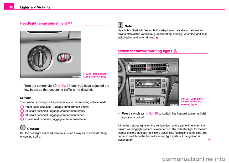
– Turn the control dial ⇒ fig. 37 until you have adjusted the
low beam so that oncoming traffic is not dazzled.
Settings
The positions correspond approximately to the following vehicle loads:
Front seats occupied, luggage compartment empty.
All seats occupied, luggage compartment empty.
All seats occupied, luggage compartment laden.
Driver seat occupied, luggage compartment laden.
Caution
Set the headlight beam adjustment in such a way as to avoid dazzling
oncoming traffic.
Note
Headlights fitted with Xenon bulbs adapt automatically to the load and
driving state of the vehicle (e.g. accelerating, braking) when the ignition is
switched on and when driving.
Switch for hazard warning lights
– Press switch ⇒ fig. 38 to switch the hazard warning light
system on or off.
All the turn signal lights on the vehicle flash at the same time when the
hazard warning light system is switched on. The indicator light for the turn
signals and the indicator light in the switch also flash at the same time. You
can also switch on the hazard warning light system if the ignition is
switched off.
Fig. 37 Dash panel:
Lights and Visibility
A-
A1
A2
A3
Fig. 38 Dash panel:
Switch for hazard
warning lights
Page 60 of 259
Lights and Visibility59
Using the systemSafetyDriving TipsGeneral MaintenanceBreakdown assistanceTechnical Data
Note
Switch on the hazard warning light system if, for example:
•you encounter traffic congestion,
•your car breaks down or an emergency situation occurs,
Turn signal and main beam lever
The parking lights and headlight flasher are also switched
on and off using the turn signal and main beam lever.
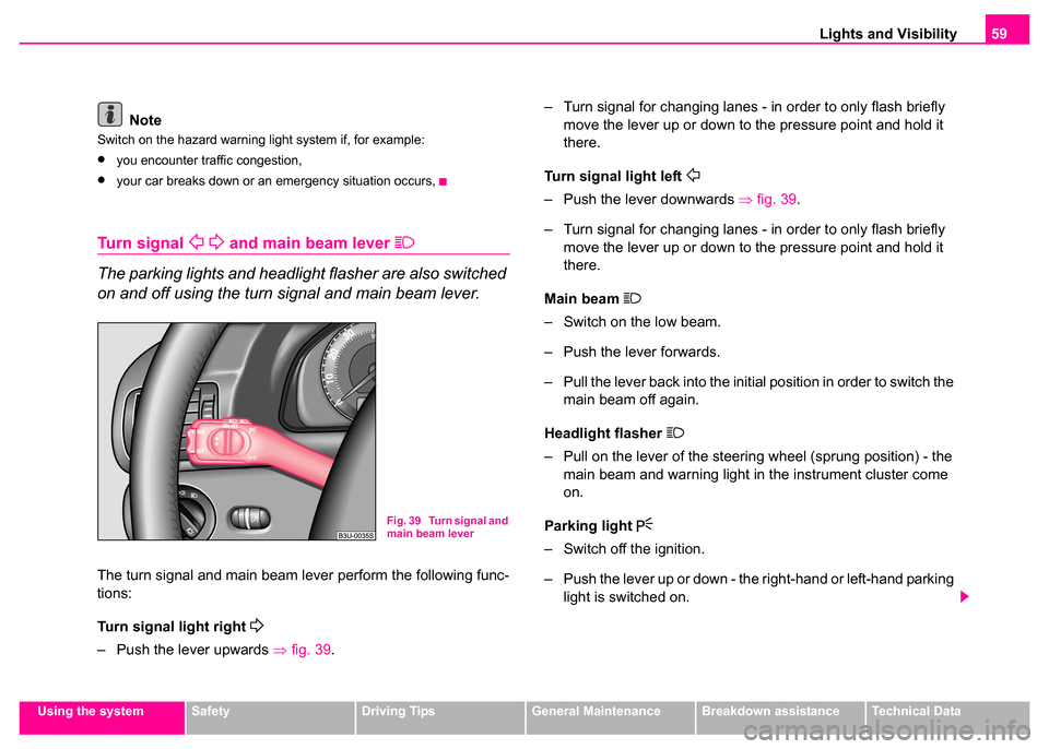
The turn signal and main beam lever perform the following func-
tions:
Turn signal light right
– Push the lever upwards ⇒fig. 39 . – Turn signal for changing lanes - in order to only flash briefly
move the lever up or down to the pressure point and hold it
there.
Turn signal light left
– Push the lever downwards ⇒fig. 39 .
– Turn signal for changing lanes - in order to only flash briefly move the lever up or down to the pressure point and hold it
there.
Main beam
– Switch on the low beam.
– Push the lever forwards.
– Pull the lever back into the initial position in order to switch the main beam off again.
Headlight flasher
– Pull on the lever of the steering wheel (sprung position) - the main beam and warning light in the instrument cluster come
on.
Parking light
– Switch off the ignition.
– Push the lever up or down - the right-hand or left-hand parking light is switched on.
Fig. 39 Turn signal and
main beam lever
Page 61 of 259
Lights and Visibility
60
Notes on light and indicator functions
•The turn signal system only operates when the ignition is switched
on. The corresponding indicator light or in the instrument cluster also
flashes.
•The turn signal is automatically cancelled after negotiating a curve.
•The side light and rear light on the appropriate side of the vehicle are
switched on when the parking light is selected. The parking light function
only operates if the ignition is switched off.
•An acoustic warning signal will sound when the driver's door is opened
if the lever is not in the middle position after removing the ignition key. The
acoustic warning signal will stop just as soon as the driver's door is closed.
Caution
•Use main beam or the headlight flasher only if this does not risk
dazzling other road users.
•Use only in accordance with the legal requirements the described
lighting and signal systems.
Coming Home-Function*
This function makes it possible to switch on low or main beam for
a short time after leaving the car, e.g. to illuminate the path to
your front door, etc.
Selecting function
– Switch off the light.
– Switch off the ignition.
– Flash one time with the headlights. – Open the door, the low beam lights up.
If you shift the lever into the main beam position, the main beam lights up.
If the door remains open, the light remains on for about 3 minutes.
If the door is closed, the light remains on for about 30 seconds.
Interior lighting
Front interior lighting and storage compartment on
front passenger side
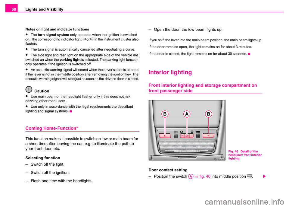
Door contact setting
– Position the switch
⇒fig. 40 into middle position
.
Fig. 40 Detail of the
headliner: front interior
lighting
AA
Page 73 of 259
Seats and Stowage
72
Emergency Off
If you operate any button or the switch ON/OFF of the driver seat, you can
interrupt the setting operation at any time in an emergency.
Storing and retrieving settings
Storing seat and exterior mirro r settings for driving forward
– Switch on the ignition.
– Adjust the seat ⇒page 70.
– Adjust both exterior mirrors ⇒page 67.
– Press one of the memory buttons and hold the button pressed for about 3 seconds until an audible signal confirms
that the setting has been stored.
Storing exterior mirror setting for reversing
– Switch on the ignition.
– Turn the exterior mirror control to position
⇒ page 67,
fig. 50 .
– Engage reverse gear.
– Move the right exterior mirror into the desired position ⇒page 67.
– Press one of the memory buttons and hold the button pressed for about 3 seconds until an audible signal confirms
that the setting has been stored. Note
•When storing settings with the memory buttons, we recommend that
you begin with the front button and assign a memory button to each addi-
tional driver.
•Each new setting stored with the same button erases the previous
setting.
•Each time you store the seat and exterior mirror settings for driving
forward you also have to re-store the individual setting of the exterior
mirror on the passenger side for reversing.
Assigning remote control to the memory buttons
After storing the settings of the seat and exterior mirrors, you
have 10 seconds in order to assign the remote control to the
appropriate memory button.
– Withdraw the ignition key.
– Press the release button ⇒page 46 and hold it pressed for 1
second until an audible signal confirms that the setting has
been stored. The setting is stored with the memory button
which you have selected.
If you wish to be able to retrieve the settings which are stored in the
memory by also using the remote control, you have to assign the remote
control to a memory button in each case.
We recommend that you assign one of the two remote controls supplied
with your car, to the front memory button, and the other remote control key
to the middle memory button.
AD
AD
Page 120 of 259

Starting-off and Driving119
Using the systemSafetyDriving TipsGeneral MaintenanceBreakdown assistanceTechnical Data
Applying the handbrake
– Pull the handbrake lever up fully.
Releasing the handbrake
– Pull the handbrake lever up slightly and at the same time
press in the locking button ⇒page 118, fig. 109 .
– Hold the button pressed and push the handbrake lever down fully ⇒ .
The handbrake warning light lights up when the handbrake is applied,
provided the ignition is on.
A warning signal (buzzer) sounds and the following text appears in the
display* if you have inadvertently driven off with the handbrake applied:
"Handbrake on"
The handbrake warning is activated if you drive at a speed of more than 5
km/h for more than 3 seconds.
Caution
After the car has come to a stop, always first of all apply the handbrake
firmly before then additionally engaging a gear (manual gearbox) or
moving the selector lever into position P (automatic gearbox).
Parking aid*
The parking aid provides a warning of obstacles behind
the vehicle.
The audible parking aid at the rear determines the distance to an obstacle
behind the car with the aid of ultrasound sensors. The sensors are inte-
grated in the rear bumper.
The parking aid is activated automatically when reverse gear is engaged
and the ignition is turned on. This is confirmed by a brief signal.
The clearance warning begins at a distance of about 160 cm from the
obstacle. The interval between the warning signals becomes shorter as
the clearance is reduced.
A continuous tone sounds from a clearance of just 30 cm - danger area.
You should not reverse any further after this signal sounds.
WARNING
•Please note that the handbrake must be fully released. A hand-
brake which is only partially released can result in the rear brakes
overheating which will have a negative effect on the operation of
the brake system - risk of accident!
•Never leave children unattended in the vehicle. The children
might, for example, release the ha ndbrake or take the vehicle out
of gear. The vehicle might then move off - risk of accident!WARNING
•The parking aid is not a substitute for the driver paying proper
attention. It is always the driver's responsibility to take care when
parking the vehicle or carrying out similar manoeuvres.
Page 239 of 259

Breakdown assistance
238
Tow-starting and towing vehicle
General
Please pay attention to the following instructions if you are going
to use a tow rope:
Driver of the towing vehicle
– Do not drive off until the tow rope is taught.
– Release the clutch particularly gently when starting off or depress the accelerator particularly gently if your vehicle is
fitted with an automatic gearbox.
Driver of th e towed vehicle
– Switch the ignition on so that the steering wheel is not blocked and you can also operate the turn signal lights, the headlight
flasher, the windscreen wipers and windscreen washer
system.
– Take the vehicle out of gear or move the selector lever into position N if your vehicle is fitted with an automatic gearbox.
– Note that the brake servo unit and power steering only operate if the engine is running. You will require significantly greater
physical force to depress the brake pedal and to steer the
vehicle if the engine is not running.
– Ensure that the tow rope is always kept taught.
Tow rope or tow bar
A tow bar is safest way of towing a vehicle and also minimizes any
shocks. You can use a tow rope only if a suitable tow bar is not available.
The tow rope must be elastic to protect the vehicle. Thus one should only
use plastic fibre rope or a rope made out of a similarly elastic material.
Attach the tow rope or the tow bar only to the towing eyes provided for
this purpose ⇒ page 239, “Towing eye” and ⇒page 239, “Rear towing
eye”.
Driving style
Towing another vehicle requires a certain amount of practice. Both drivers
should be familiar with the particular points about towing a vehicle.
Unskilled drivers should not attempt to tow-start or tow in another vehicle.
One should be constantly vigilant not to allow impermissibly high towing
forces or jerky loadings. There is always a risk of excessive stresses and
damage resulting at the points to which you attach the tow rope or tow bar
when you attempt to tow a vehicle which is not standing on a paved road.
Caution
If the gearbox of your vehicle no longer contains any oil because of a
defect, your vehicle must only be towed in with the driven wheels raised
clear of the ground, or on a special vehicle transporter or trailer.
Note
Please comply with any legal requirements particularly regarding the
switched on signal systems, when towing in or tow-starting another
vehicle.
Page 243 of 259
Fuses and light bulbs
242
Caution
•Never attempt to “repair” fuses and also do not replace them with a
fuse of a higher amperage - risk of fire! This may also cause damage at
another part of the electrical system.
•Have the electrical system checked as quickly as possible by a Škoda
dealer if a newly inserted fuse blows again after a short time.
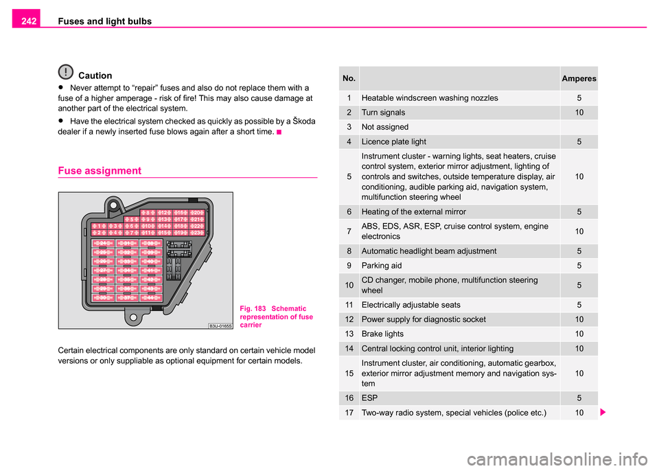
Fuse assignment
Certain electrical components are only standard on certain vehicle model
versions or only suppliable as optional equipment for certain models.
Fig. 183 Schematic
representation of fuse
carrier
No.Amperes
1Heatable windscreen washing nozzles5
2Turn signals10
3Not assigned
4Licence plate light5
5
Instrument cluster - warning lights, seat heaters, cruise
control system, exterior mirror adjustment, lighting of
controls and switches, outside temperature display, air
conditioning, audible parking aid, navigation system,
multifunction steering wheel
10
6Heating of the external mirror5
7ABS, EDS, ASR, ESP, cruise control system, engine
electronics10
8Automatic headlight beam adjustment5
9Parking aid5
10CD changer, mobile phone, multifunction steering
wheel5
11Electrically adjustable seats5
12Power supply for diagnostic socket10
13Brake lights10
14Central locking control unit, interior lighting10
15Instrument cluster, air conditioning, automatic gearbox,
exterior mirror adjustment memory and navigation sys-
tem10
16ESP5
17Two-way radio system, special vehicles (police etc.)10
Page 245 of 259
Fuses and light bulbs
244
removed in order to change the light bulbs. This applies, in particular, to
bulbs which can only be reached from the engine compartment.
We therefore recommend that you have any bulbs changed by a Škoda
dealer or, in exceptional cases, by calling on other professional assist-
ance.
Please note that the engine compartment is a hazardous area
⇒ page 203, “Working in the engine compartment”.
We recommend that you carry the set of light bulbs with you which was
delivered in your vehicle. Replacement light bulbs
5) are available at
Škoda dealers.
Fitted with a xenon headlight
Change of light bulbs on Xenon lights (low beam lights, parking lights and
main beam lights) should be undertaken by a Skoda dealer.
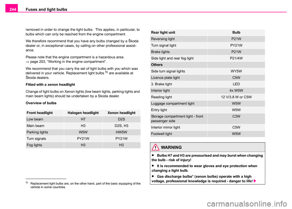
Overview of bulbs
5)Replacement light bulbs are, on the other hand, part of the basic equipping of the
vehicle in some countries.
Front headlightHalogen headlightXenon headlight
Low beamH7D2S
Main beamH3D2S, H3
Parking lightsW5WHW5W
Turn signalsPY21WPY21W
Fog lightsH3H3
Rear light unitBulb
Reversing lightP21W
Turn signal lightPY21W
Brake lightsP21W
Side light and rear fog lightP21/4W
Others
Side turn signal lightsWY5W
Licence plate lightC5W
3. Brake lightLED
Interior light4x W5W
Reading light12 V/3.8 W or C5W
Luggage compartment lightW5W
Entry lightW5W
Storage compartment light - front
passenger sideC3W
Interior mirror lightC5W
Footwell lightW5W
WARNING
•Bulbs H7 and H3 are pressurised and may burst when changing
the bulb - risk of injury!
•It is recommended to wear gloves and eye protection when
changing a light bulb.
•Gas discharge bulbs* (xenon bu lbs) operate with a high
voltage, professional knowledge is required - danger to life!
Page 256 of 259
Index255
Starting engine . . . . . . . . . . . . . . . . . . . . . . 115
after fuel tank has run empty . . . . . . . . . 117
Diesel engine . . . . . . . . . . . . . . . . . . . . . 116
Petrol engine . . . . . . . . . . . . . . . . . . . . . 116
Storage compartment Door trim panels . . . . . . . . . . . . . . . . . . . . 98
Lighting . . . . . . . . . . . . . . . . . . . . . . . . . . 60
Umbrella . . . . . . . . . . . . . . . . . . . . . . . . . . 99
Storage compartments . . . . . . . . . . . . . . . . . 95
Storage drawer . . . . . . . . . . . . . . . . . . . . . . . 96
Storage facilities . . . . . . . . . . . . . . . . . . . . . . 95
Stowage compartment below steering wheel 98
Sun visors . . . . . . . . . . . . . . . . . . . . . . . . . . . 63
Switch on the driver's door Power windows . . . . . . . . . . . . . . . . . . . . 49
Switching the engine off . . . . . . . . . . . . . . . 117
T
Taking care of your vehicle . . . . . . . . . . . . . 189
TCS Warning light . . . . . . . . . . . . . . . . . . . . . . 34
Telephone . . . . . . . . . . . . . . . . . . . . . . . . . . 132
The air conditioning system . . . . . . . . . . . . . 102
The armrest at the rear . . . . . . . . . . . . . . . . 101
The automatic wiper/washer system . . . . . . . 64 The battery . . . . . . . . . . . . . . . . . . . . . . . . . . 212
changing . . . . . . . . . . . . . . . . . . . . . . . . . 216
charging . . . . . . . . . . . . . . . . . . . . . . . . . 214
disconnecting and connecting . . . . . . . . 216
Inspecting the electrolyte level . . . . . . . . 214
Operation in winter . . . . . . . . . . . . . . . . . 214
The electronic immobiliser . . . . . . . . . . . . 35, 39
The radiator fan . . . . . . . . . . . . . . . . . . . . . . 210
The roof luggage rack system . . . . . . . . . . . . 88
Thickness of brake pads Warning light . . . . . . . . . . . . . . . . . . . . . . 32
Through-loading bag . . . . . . . . . . . . . . . . . . . 81
Tiptronic . . . . . . . . . . . . . . . . . . . . . . . . . . . . 123
Tool . . . . . . . . . . . . . . . . . . . . . . . . . . . . . . . 228
Towing a vehicle . . . . . . . . . . . . . . . . . . . . . 238
Towing eye at the front . . . . . . . . . . . . . . . . . . . . . . . 239
at the rear . . . . . . . . . . . . . . . . . . . . . . . . 239
Tow-starting a vehicle . . . . . . . . . . . . . . . . . 238
Tow-starting and towing vehicle Automatic gearbox . . . . . . . . . . . . . . . . . 129
Traction Control System Operating principle . . . . . . . . . . . . . . . . . 170
Trailer . . . . . . . . . . . . . . . . . . . . . . . . . . . . . . 184 Driving Tips . . . . . . . . . . . . . . . . . . . . . . 185
General Maintenance . . . . . . . . . . . . . . . 184
technical aspects . . . . . . . . . . . . . . . . . . 184
Transporting children . . . . . . . . . . . . . . . . . . 157
Tread depth . . . . . . . . . . . . . . . . . . . . . . . . . 221
Trip counter for distance driven . . . . . . . . . . . 16 Turn signal system for vehicles towing a trailer
Warning light . . . . . . . . . . . . . . . . . . . . . . . 30
Turn signals Warning light . . . . . . . . . . . . . . . . . . . . . . . 29
Two-way radio sets . . . . . . . . . . . . . . . . . . . 135
Two-way radio systems mobile . . . . . . . . . . . . . . . . . . . . . . . . . . . 135
Type plate . . . . . . . . . . . . . . . . . . . . . . . . . . 249
Tyres . . . . . . . . . . . . . . . . . . . . . . . . . . . . . . 220
U
Underbody protection . . . . . . . . . . . . . . . . . . 193
Unlocking . . . . . . . . . . . . . . . . . . . . . . . . . . . . 39 Remote control . . . . . . . . . . . . . . . . . . . . . 46
V
Vanity mirror . . . . . . . . . . . . . . . . . . . . . . . . . . 63
Vehicle electrics . . . . . . . . . . . . . . . . . . . . . . . 36
Vehicle identification data . . . . . . . . . . . . . . 249
Vehicle tool kit . . . . . . . . . . . . . . . . . . . . . . . 228
W
Warning lights . . . . . . . . . . . . . . . . . . . . . . . . 28
Warning symbols on the instrument cluster . . 28
Warning triangle . . . . . . . . . . . . . . . . . . . . . . 227
WashingWash systems . . . . . . . . . . . . . . . . . . . . 190
with high-pressure cleaner . . . . . . . . . . . 191