turn signal SKODA SUPERB 2006 1.G / (B5/3U) User Guide
[x] Cancel search | Manufacturer: SKODA, Model Year: 2006, Model line: SUPERB, Model: SKODA SUPERB 2006 1.G / (B5/3U)Pages: 281, PDF Size: 12.67 MB
Page 61 of 281
Lights and Visibility
60
The turn signal and main beam lever perform the following func-
tions:
Right
and left turn signal light
– Push the lever upwards or downwards ⇒page 59, fig. 40 .
– Turn signal for changing lanes - in order to only flash briefly, move the lever up or down to the pressure point and hold it in
this position.
Main beam
– Switch on the low beam.
– Push the lever forwards.
– Pull the lever back into the initial position in order to switch the main beam off again.
Headlight flasher
– Pull on the lever of the steering wheel (sprung position) - the main beam and warning light in the instrument cluster come
on.
Parking light
– Switch off the ignition.
– Push the lever up or down - the right-hand or left-hand parking light is switched on.
Notes on light and indicator functions
•The turn signal system only operates when the ignition is switched
on. The corresponding indicator light or in the instrument cluster also
flashes.
•The turn signal is automatically cancelled after negotiating a curve.
•The side light and rear light on the appropriate side of the vehicle are
switched on when the parking light is selected. The parking light function
only operates if the ignition is switched off.
•An acoustic warning signal will sound when the driver's door is opened
if the lever is not in the middle position after removing the ignition key. The
acoustic warning signal will stop just as soon as the driver's door is closed.
Caution
Use main beam or the headlight flasher only if this does not risk dazzling
other road users.
Note
Use only in accordance with the legal requirements the described lighting
and signal systems.
Coming Home Function
This function makes it possible to switch on low or main beam for
a short time after leaving the car, e.g. to illuminate the path to
your front door, etc.
Selecting function
– Switch off the light.
– Switch off the ignition.
– Flash one time with the headlights.
– Open the door, the low beam lights up.
NKO B5 20.book Page 60 Monday, July 3, 2006 2:09 PM
Page 75 of 281
Seats and Stowage
74
Memory for the seat
Memory buttons
Memory for the seat offers the possibility to store the individual seat and
external mirror position. An individual position can be allocated to each of
the three memory buttons ⇒fig. 56 , that is three in total. On pressing
the appropriate memory button the seat and external mirror will auto-
matically move into the position allocated to this button.
ON/OFF switch
If you press switch (increased switch position), the memory buttons
no longer operate. You can now adjust the seat electrically without using
the memory buttons . After pressing switch once again, the seat can
be reset with the memory buttons. If you had already started an operation
to retrieve the settings, this operation is not continued.
If the car is used only by one driver, it is not necessary to store particular
settings in this case, we recommend that you press the button
(increased switch position). Emergency Off
If you operate any button or the switch ON/OFF switch of the driver seat,
you can interrupt the setting operation at any time in an emergency.
Storing and retrieving settings
Storing seat and exterio
r mirror settings for driving forward
– Switch on the ignition.
– Adjust the seat ⇒ page 73.
– Adjust both exterior mirrors ⇒page 69.
– Press the desired memory button and hold the button pressed for about 3 seconds until an audible signal confirms
that the setting has been stored.
Storing exterior mirror setting for reversing
– Switch on the ignition.
– Turn the exterior mirror control to position
⇒ page 69,
fig. 53.
– Engage reverse gear.
– Move the right exterior mirror into the desired position ⇒page 69.
– Press the desired memory button and hold the button pressed for about 3 seconds until an audible signal confirms
that the setting has been stored.
Fig. 56 Driver seat:
Memory buttons and
ON/OFF switch
ADAD
AEAD
ADAE
AE
AD
AD
NKO B5 20.book Page 74 Monday, July 3, 2006 2:09 PM
Page 86 of 281

Seats and Stowage85
Using the systemSafetyDriving TipsGeneral MaintenanceBreakdown assistanceTechnical Data
Folding down the backrest of the rear seats*
The luggage compartment can be enlarged if necessary by
folding one or both seat backrests forward. Folding the seat backrest forwards
– Before folding the seat backrest forwards, the front seats must
be adjusted so that the front seats are not damaged when
folding the seat backrest forwards.
– Pull the unlocking knob ⇒fig. 71 and fold the rear seat
backrest forwards completely.
Fold the seat backrest back into position
– Place the rear lateral seat belt behind the edge of the side trim panel.
– Then push the seat backrest back into the upright position until the locking button clicks into place - check by pulling on
the rear seat backrest.
– Ensure that the red surface on the front side of the knob is not visible.
Blocking the unlock knobs
– Fold the seat backrest back into position and ensure that it is correctly interlocked.
– The unlock knobs are blocked by turning the slit in the lock to the right ⇒fig. 72 with the master key.
Unblock the unlock knobs
– The unlock knobs are unblocked by turning the slit in the lock to the left with the master key.The rear seat is equipped with an audible signaling of the rear seat back-
rest securing system. When the seat backrest is unlocked, the red surface
Fig. 71 Unlock the seat
backrest
Fig. 72 Blocking the
unlock knob
AA
AB
AA
NKO B5 20.book Page 85 Monday, July 3, 2006 2:09 PM
Page 127 of 281

Starting-off and Driving
126
Caution
After the car has come to a stop, always first of all apply the handbrake
firmly before then additionally engaging a gear (manual gearbox) or
moving the selector lever into position P (automatic gearbox).
Parking aid*
The parking aid provides a warning of obstacles behind
the vehicle.
The audible parking aid determines the distance between the rear bumper
and an obstacle located behind the vehicle with the aid of ultrasound
sensors. The sensors are integrated in the rear bumper. Range of sensors
The clearance warning begins at a distance of about 160 cm from the
obstacle (area
⇒fig. 119 ). The interval between the warning signals
becomes shorter as the clearance is reduced.
A continuous tone sounds from a clearance of just 30 cm (Bereich ) -
danger area. From this moment on do not continue driving in the
selected direction or the direction from where the obstacle is
reported!
Activating
The parking aid is activated automatically when reverse gear is engaged
and the ignition is turned on. This is confirmed by a brief acknowledge-
ment signal.
Deactivating
The parking aid is deactivated by removing the reverse gear.
WARNING
•The parking aid is not a substitute for the driver paying proper
attention and it is always the driver's responsibility to take care
when parking the vehicle or carrying out similar manoeuvres.
•You should therefore satisfy yourself, before reversing, that
there is no small obstacle, such as a rock, thin post, trailer drawbar
etc., behind your vehicle. Such an obstacle might not be within the
range detected by the sensors.
Note
•The parking aid does not operate if you are towing a trailer (applies to
models which feature a factory-fitted towing device*).
•If a warning signal sounds for about 3 seconds after switching the igni-
tion on and engaging reverse gear, and there is no obstacle close to your
Fig. 119 Parking aid:
Detection range of rear
sensors
AA
AB
NKO B5 20.book Page 126 Monday, July 3, 2006 2:09 PM
Page 128 of 281

Starting-off and Driving127
Using the systemSafetyDriving TipsGeneral MaintenanceBreakdown assistanceTechnical Data
car, this indicates a system fault. Have the fault rectified by a specialist
workshop.
•The sensors must be kept clean and free of ice to enable the parking
aid to operate properly.
Front and rear parking aid*
The parking aid provides a warning of obstacles in front
and behind the vehicle.
The audible parking aid determines the distance between the front or rear
bumper and an obstacle with the aid of ultrasound sensors. The sensors
are integrated in the front and rear bumper. The signal tones for the front
parking aid sound lower than for the rear parking aid.
Range of sensors
The distance warning begins at a distance of about 60 cm from the
obstacle in front of the vehicle (area ⇒fig. 121 ) and about 160 cm
from the obstacle behind the vehicle (area ⇒page 126, fig. 119 ). The
interval between the warning signals becomes shorter as the clearance is
reduced.
A continuous tone sounds from a clearance of just 30 cm (Bereich ) -
danger area. From this moment on do not continue driving in the
selected direction or the direct ion from where the obstacle is
reported!
Activating
The parking aid is activated when the reverse gear is engaged and the
ignition is turned on or by pressing the button ⇒fig. 120 - the symbol
Fig. 120 Activating the
parking aid
Fig. 121 Parking aid:
Detection range of the
front sensors
AAAA
AB
NKO B5 20.book Page 127 Monday, July 3, 2006 2:09 PM
Page 151 of 281
Passive Safety
150
For this reason you will be provided with information on why this equip-
ment is very important, how it protects you and the occupants, what
should be observed when using the equipment and how you and the
people travelling with you can make full use of the existing safety equip-
ment. This Owner's Manual contains important warning notes, which you
and those travelling with you should pay attention to in order to reduce a
risk of injury.
Safety concerns everybody!
Before setting off
The driver is always fully responsible for his occupants
and for the operating safety of the vehicle.
For your own safety and the safety of the people travelling with you,
please pay attention to the following points before setting off.
•Ensure that the lighting and the turn signal system are functioning
properly.
•Inspect the tyre inflation pressure.
•Ensure that all the windows offer a good visibility to the outside.
•Safely attach the items of luggage ⇒page 81, “Loading the luggage
compartment”.
•Ensure that no objects can obstruct the pedal.
•Adjust the mirror, the front seat and the head restraint to match your
body size.
•Point out to your occupants that the head restraints must be adjusted
to match their body size.
•Protect the children in suitable child seats with correctly fastened seat
belts ⇒page 174, “Transporting children safely”.
•Adopt the correct seated position ⇒page 151. Also inform your occu-
pants to adopt the correct seated position.
•Fasten the seat belt correctly. Also inform your occupants to properly
fasten the seat belts ⇒page 158, “How are seat belts correctly
fastened?”.
What influences the driving safety?
The driving safety is primarily determined by the style of
driving and the personal behaviour of all the occupants.
The driver is fully responsible for himself and his occupants. If your driving
safety is effected, you place yourself and the oncoming traffic at risk.
Please refer to the following guidelines.
•Do not get distracted from concentrating on the traffic situation, e.g. by
your occupants or mobile phone calls.
•Never drive when your driving ability is impaired, e.g. through medica-
tion, alcohol, drugs.
•Keep to the traffic regulations and the permissible speed limit.
•Adjust the driving speed at all times to the road condition as well as to
the traffic and weather conditions.
•Take regular breaks on long journeys - at the latest every two hours.
NKO B5 20.book Page 150 Monday, July 3, 2006 2:09 PM
Page 258 of 281
Breakdown assistance257
Using the systemSafetyDriving TipsGeneral MaintenanceBreakdown assistanceTechnical Data
out the battery being ignited by the strong spark which results from
the engine being started.
•Do not affix the cable end to parts of the fuel and brake
system.
•Run the jump-start cables so that they cannot be caught by any
rotating parts in the engine compartment.
•Do not bend over the batteries - risk of caustic burns!
•The vent screws of the battery cells must be tightened firmly.
•Keep any sources of ignition (naked flame, smouldering ciga-
rettes etc.) away from the battery - risk of an explosion!
Tow-starting and towing vehicle
General
Please pay attention to the following instructions if you are going
to use a tow rope:
Driver of the towing vehicle
– Do not drive off until the tow rope is taught.
– Release the clutch particularly gently when starting off or depress the accelerator particularly gently if your vehicle is
fitted with an automatic gearbox. Driver of the towed vehicle
– Switch the ignition on so that the steering wheel is not blocked
and you can also operate the turn signal lights, the headlight
flasher, the windscreen wipers and windscreen washer
system.
– Take the vehicle out of gear or move the selector lever into position N if your vehicle is fitted with an automatic gearbox.
– Note that the brake servo unit and power steering only operate if the engine is running. You will require significantly greater
physical force to depress the brake pedal and to steer the
vehicle if the engine is not running.
– Ensure that the tow rope is always kept taught.
Tow rope or tow bar
A tow bar is safest way of towing a vehicle and also minimizes any
shocks. You can use a tow rope only if a suitable tow bar is not available.
The tow rope must be elastic to protect the vehicle. Thus one should only
use plastic fibre rope or a rope made out of a similarly elastic material.
Attach the tow rope or the tow bar only to the towing eyes provided for
this purpose ⇒page 258, “Front towing eye” and ⇒page 258, “Rear
towing eye”.
Driving style
Towing another vehicle requires a certain amount of practice. Both drivers
should be familiar with the particular points about towing a vehicle.
Unskilled drivers should not attempt to tow in another vehicle or to be
towed in.
One should be constantly vigilant not to allow impermissibly high towing
forces or jerky loadings. There is always a risk of excessive stresses and
WARNING (continued)
A4
NKO B5 20.book Page 257 Monday, July 3, 2006 2:09 PM
Page 262 of 281
Fuses and light bulbs261
Using the systemSafetyDriving TipsGeneral MaintenanceBreakdown assistanceTechnical Data
Caution
•Never attempt to “repair” fuses and also do not replace them with a
fuse of a higher amperage - risk of fire! This may also cause damage at
another part of the electrical system.
•Have the electrical system checked as quickly as possible by a
specialist garage if a newly inserted fuse blows again after a short time.
Note
We recommend that you have these fuses replaced by a specialist
garage.
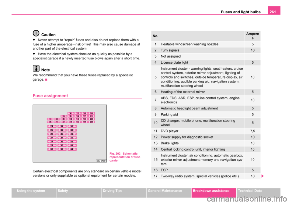
Fuse assignment
Certain electrical components are only standard on certain vehicle model
versions or only suppliable as optional equipment for certain models.
Fig. 202 Schematic
representation of fuse
carrier
No.Ampere
s
1Heatable windscreen washing nozzles5
2Turn signals10
3Not assigned
4Licence plate light5
5
Instrument cluster - warning lights, seat heaters, cruise
control system, exterior mirror adjustment, lighting of
controls and switches, outside temperature display, air
conditioning, audible parking aid, navigation system,
multifunction steering wheel
10
6Heating of the external mirror5
7ABS, EDS, ASR, ESP, cruise control system, engine
electronics10
8Automatic headlight beam adjustment5
9Parking aid5
10CD changer, mobile phone, multifunction steering
wheel5
11DVD player7,5
12Power supply for diagnostic socket10
13Brake lights10
14Central locking control unit, interior lighting10
15Instrument cluster, air conditioning, automatic gearbox,
exterior mirror adjustment memory and navigation sys-
tem10
16ESP5
17Two-way radio system, special vehicles (police etc.)10
NKO B5 20.book Page 261 Monday, July 3, 2006 2:09 PM
Page 264 of 281
Fuses and light bulbs263
Using the systemSafetyDriving TipsGeneral MaintenanceBreakdown assistanceTechnical Data
removed in order to change the light bulbs. This applies, in particular, to
bulbs which can only be reached from the engine compartment.
We therefore recommend that you have any bulbs changed by a Škoda
Service Partner or, in exceptional cases, by calling on other professional
assistance.
Please note that the engine compartment is a hazardous area
⇒
page 219, “Working in the engine compartment”.
We recommend that you carry the set of light bulbs with you which was
delivered in your vehicle. Replacement light bulbs
6) are available at
specialist garages.
Fitted with a xenon headlight
Change of light bulbs on Xenon lights (low beam lights, parking lights and
main beam lights) should be undertaken by a specialist garage.
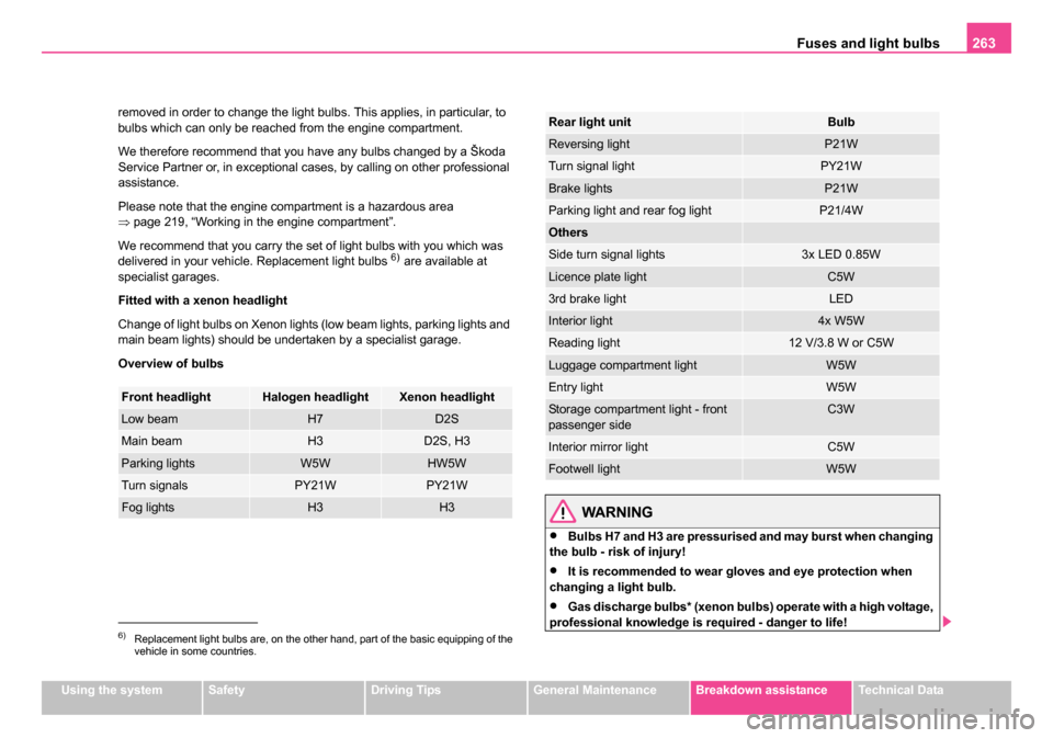
Overview of bulbs
WARNING
•Bulbs H7 and H3 are pressurised and may burst when changing
the bulb - risk of injury!
•It is recommended to wear gloves and eye protection when
changing a light bulb.
•Gas discharge bulbs* (xenon bulbs) operate with a high voltage,
professional knowledge is required - danger to life!
6)Replacement light bulbs are, on the other hand, part of the basic equipping of the
vehicle in some countries.
Front headlightHalogen headlightXenon headlight
Low beamH7D2S
Main beamH3D2S, H3
Parking lightsW5WHW5W
Turn signalsPY21WPY21W
Fog lightsH3H3
Rear light unitBulb
Reversing lightP21W
Turn signal lightPY21W
Brake lightsP21W
Parking light and rear fog lightP21/4W
Others
Side turn signal lights3x LED 0.85W
Licence plate lightC5W
3rd brake lightLED
Interior light4x W5W
Reading light12 V/3.8 W or C5W
Luggage compartment lightW5W
Entry lightW5W
Storage compartment light - front
passenger sideC3W
Interior mirror lightC5W
Footwell lightW5W
NKO B5 20.book Page 263 Monday, July 3, 2006 2:09 PM
Page 277 of 281
Index
276
Safety information
Engine compartment . . . . . . . . . . . . . . . 219
Saving electrical energy . . . . . . . . . . . . . . . 194
Seat belt height adjuster . . . . . . . . . . . . . . . 159
Seat belt warning light . . . . . . . . . . . . . . . . 158
Seat belts . . . . . . . . . . . . . . . . . . . . . . . . . . 155 Belt tensioners . . . . . . . . . . . . . . . . . . . 160
Cleaning . . . . . . . . . . . . . . . . . . . . . . . . 213
fastening . . . . . . . . . . . . . . . . . . . . . . . . 158
Height adjustment . . . . . . . . . . . . . . . . . 159
Safety information . . . . . . . . . . . . . . . . . 157
taking off . . . . . . . . . . . . . . . . . . . . . . . . 159
Warning light . . . . . . . . . . . . . . . . . . . . . . 37
Seat heaters . . . . . . . . . . . . . . . . . . . . . . . . . 80
Seats . . . . . . . . . . . . . . . . . . . . . . . . . . . . . . . 71 Heater . . . . . . . . . . . . . . . . . . . . . . . . . . . 80
Selector lever . . . . . . . . . . . . . . . . . . . . . . . 132
Selector lever positions . . . . . . . . . . . . . . . . 132
Service Interval Display . . . . . . . . . . . . . . . . 16
Service intervals . . . . . . . . . . . . . . . . . . . . . . 16
Service key . . . . . . . . . . . . . . . . . . . . . . . . . . 38
Setting temperature Air conditioning system . . . . . . . . . . . . . 109
Setting the clock . . . . . . . . . . . . . . . . . . . . . . 15
Shifting . . . . . . . . . . . . . . . . . . . . . . . . . . . . 124
Side airbag . . . . . . . . . . . . . . . . . . . . . . . . . 166
Side lights . . . . . . . . . . . . . . . . . . . . . . . . . . . 56
Ski bag . . . . . . . . . . . . . . . . . . . . . . . . . . . . . 87
Snow chains . . . . . . . . . . . . . . . . . . . . . . . . 241
Spare wheel . . . . . . . . . . . . . . . . . . . . . . . . 247 Speedometer . . . . . . . . . . . . . . . . . . . . . . . . 16
Stability programme . . . . . . . . . . . . . . . . . . 185
Starting the engine . . . . . . . . . . . . . . . . . . . 122
Diesel engines . . . . . . . . . . . . . . . . . . . . 123
Petrol engines . . . . . . . . . . . . . . . . . . . . 123
Steering booster . . . . . . . . . . . . . . . . . . . . . 191
Storage compartment Centre console . . . . . . . . . . . . . . . . . . . 103
Drawer compartment . . . . . . . . . . . . . . . 102
Lighting . . . . . . . . . . . . . . . . . . . . . . . . . . 61
Spectacles . . . . . . . . . . . . . . . . . . . . . . . 103
Storage compartments . . . . . . . . . . . . . . . . 101
Storage drawer . . . . . . . . . . . . . . . . . . . . . . 102
Storage facilities . . . . . . . . . . . . . . . . . . . . . 101
Stowage compartment Armrest with stowage compartment . . . 106
Door panels . . . . . . . . . . . . . . . . . . . . . . 104
Umbrella . . . . . . . . . . . . . . . . . . . . . . . . 105
Stowage compartment below steering wheel . . . 104
Sun screen . . . . . . . . . . . . . . . . . . . . . . . . . . 64
Sun visors . . . . . . . . . . . . . . . . . . . . . . . . . . . 64
Switching lights on and off . . . . . . . . . . . . . . 56
Switching the engine off . . . . . . . . . . . . . . . . . . . . . . . . 123
Switching the engine off . . . . . . . . . . . . . . . 123
T
Taking care of your vehicle . . . . . . . . . . . . . 205 TCS . . . . . . . . . . . . . . . . . . . . . . . . . . . . . . . 186
Warning light . . . . . . . . . . . . . . . . . . . . . . 35
Telephone . . . . . . . . . . . . . . . . . . . . . . . . . . 145
Temperature outside . . . . . . . . . . . . . . . . . . . . . . . . . . . 20
the first 1 500 kilometres . . . . . . . . . . . . . . . 192
The roof luggage rack system . . . . . . . . . . . . 94
Thickness of brake pads Warning light . . . . . . . . . . . . . . . . . . . . . . 32
Through-loading bag . . . . . . . . . . . . . . . . . . . 87
Tilting roof . . . . . . . . . . . . . . . . . . . . . . . . . . . 52
Tiptronic . . . . . . . . . . . . . . . . . . . . . . . . . . . . 135
Tool . . . . . . . . . . . . . . . . . . . . . . . . . . . . . . . 246
Towing a trailer . . . . . . . . . . . . . . . . . . . . . . 200
Towing device . . . . . . . . . . . . . . . . . . . . . . . 202
Towing eye front . . . . . . . . . . . . . . . . . . . . . . . . . . . . 258
rear . . . . . . . . . . . . . . . . . . . . . . . . . . . . . 258
towing vehicle . . . . . . . . . . . . . . . . . . . . . . . 257
Tow-starting . . . . . . . . . . . . . . . . . . . . . . . . . 257
Traction control system (TCS) . . . . . . . . . . . 186 Warning light . . . . . . . . . . . . . . . . . . . . . . 35
Trailer . . . . . . . . . . . . . . . . . . . . . . . . . . . . . 200 General Maintenance . . . . . . . . . . . . . . . 200
Transporting children safely . . . . . . . . . . . . 174
Tread depth . . . . . . . . . . . . . . . . . . . . . . . . . 237
Turn signal lights . . . . . . . . . . . . . . . . . . . . . . 59 Warning light . . . . . . . . . . . . . . . . . . . . . . 28
Turn signal system for vehicles towing a trailer Warning light . . . . . . . . . . . . . . . . . . . . . . 29
NKO B5 20.book Page 276 Monday, July 3, 2006 2:09 PM