SKODA SUPERB 2006 1.G / (B5/3U) Owner's Manual
Manufacturer: SKODA, Model Year: 2006, Model line: SUPERB, Model: SKODA SUPERB 2006 1.G / (B5/3U)Pages: 281, PDF Size: 12.67 MB
Page 261 of 281

Fuses and light bulbs
260
Fuses and light bulbs
Electric fuses
Replacing fuses
Defect fuses must be replaced.
Individual electrical circuits are protected by fuses. The fuses are
located on the left side of the dash panel behind the safety cover.
– Switch the ignition off and also the electrical component
affected.
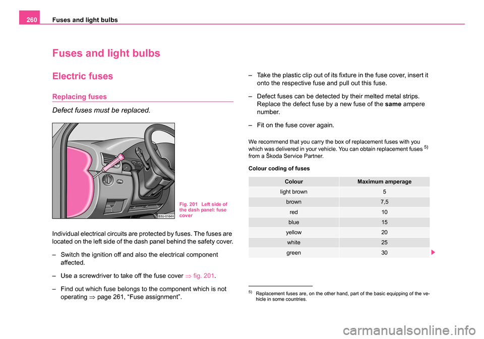
– Use a screwdriver to take off the fuse cover ⇒fig. 201.
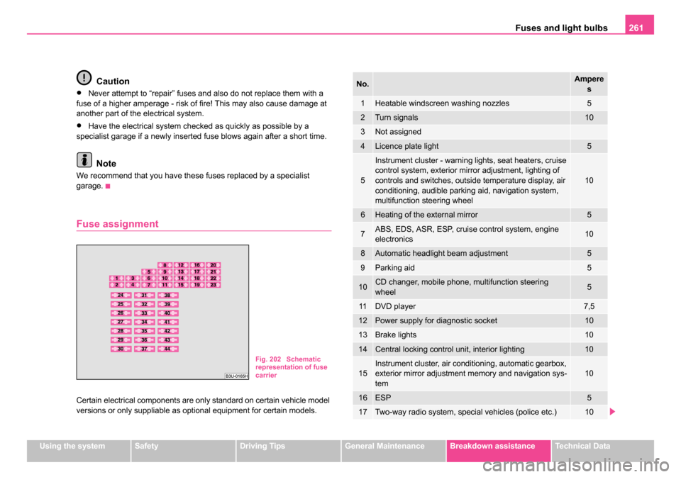
– Find out which fuse belongs to the component which is not operating ⇒page 261, “Fuse assignment”. – Take the plastic clip out of its fixture in the fuse cover, insert it
onto the respective fuse and pull out this fuse.
– Defect fuses can be detected by their melted metal strips. Replace the defect fuse by a new fuse of the same ampere
number.
– Fit on the fuse cover again.
We recommend that you carry the box of replacement fuses with you
which was delivered in your vehicle. You can obtain replacement fuses 5)
from a Škoda Service Partner.
Colour coding of fuses
Fig. 201 Left side of
the dash panel: fuse
cover
5)Replacement fuses are, on the other hand, part of the basic equipping of the ve-
hicle in some countries.
ColourMaximum amperage
light brown5
brown7,5
red10
blue15
yellow20
white25
green30
NKO B5 20.book Page 260 Monday, July 3, 2006 2:09 PM
Page 262 of 281

Fuses and light bulbs261
Using the systemSafetyDriving TipsGeneral MaintenanceBreakdown assistanceTechnical Data
Caution
•Never attempt to “repair” fuses and also do not replace them with a
fuse of a higher amperage - risk of fire! This may also cause damage at
another part of the electrical system.
•Have the electrical system checked as quickly as possible by a
specialist garage if a newly inserted fuse blows again after a short time.
Note
We recommend that you have these fuses replaced by a specialist
garage.
Fuse assignment
Certain electrical components are only standard on certain vehicle model
versions or only suppliable as optional equipment for certain models.
Fig. 202 Schematic
representation of fuse
carrier
No.Ampere
s
1Heatable windscreen washing nozzles5
2Turn signals10
3Not assigned
4Licence plate light5
5
Instrument cluster - warning lights, seat heaters, cruise
control system, exterior mirror adjustment, lighting of
controls and switches, outside temperature display, air
conditioning, audible parking aid, navigation system,
multifunction steering wheel
10
6Heating of the external mirror5
7ABS, EDS, ASR, ESP, cruise control system, engine
electronics10
8Automatic headlight beam adjustment5
9Parking aid5
10CD changer, mobile phone, multifunction steering
wheel5
11DVD player7,5
12Power supply for diagnostic socket10
13Brake lights10
14Central locking control unit, interior lighting10
15Instrument cluster, air conditioning, automatic gearbox,
exterior mirror adjustment memory and navigation sys-
tem10
16ESP5
17Two-way radio system, special vehicles (police etc.)10
NKO B5 20.book Page 261 Monday, July 3, 2006 2:09 PM
Page 263 of 281

Fuses and light bulbs
262
The power windows and the power seats are protected by automatic
circuit breakers which switch on again automatically after a few seconds
after the overload has been eliminated - e.g. frozen windows.
Bulbs
Changing bulbs
The relevant lamp must always be switched off before a light bulb is
replaced.
Do not take hold of the glass bulb with naked fingers (even the smallest
amount of dirt reduces the working life of the light bulb). Use a clean cloth,
serviette or something similar.
Defect light bulbs should only be replaced with light bulbs of the same
type. The designation is located on the light socket or the glass bulb.
Changing certain bulbs is not something which you can do yourself, but
requires to be done by a specialist. Other parts of the vehicle must be
18Right main beam10
19Left main beam10
20Low beam on the right15
21Low beam on the left15
22Parking light on the right5
23Parking light on the left5
24Windscreen washer system, windscreen wiper pump
and intermittent switch25
25Fan for fresh air, the air conditioning unit, Climatronic30
26Rear window heating, recirculated air mode30
27Not assigned
28Fuel pump, diesel additional pump20
29Engine control20
30Electric sliding/tilting roof/DVD player20/7,5
31Reversing lights, cruise control system, automatic
gearbox, automatic dimming interior mirror15
32Engine control, cruise control system20
33Cigarette lighter15
34Engine control15
35Trailer socket30
36Fog lights15
37Radio, navigation20
38Central locking system15
No.Ampere s
39Hazard warning light system15
40Horn25
41Not assigned
42ESP25
43Engine control15
44Seat heaters30
No.Amperes
NKO B5 20.book Page 262 Monday, July 3, 2006 2:09 PM
Page 264 of 281

Fuses and light bulbs263
Using the systemSafetyDriving TipsGeneral MaintenanceBreakdown assistanceTechnical Data
removed in order to change the light bulbs. This applies, in particular, to
bulbs which can only be reached from the engine compartment.
We therefore recommend that you have any bulbs changed by a Škoda
Service Partner or, in exceptional cases, by calling on other professional
assistance.
Please note that the engine compartment is a hazardous area
⇒
page 219, “Working in the engine compartment”.
We recommend that you carry the set of light bulbs with you which was
delivered in your vehicle. Replacement light bulbs
6) are available at
specialist garages.
Fitted with a xenon headlight
Change of light bulbs on Xenon lights (low beam lights, parking lights and
main beam lights) should be undertaken by a specialist garage.
Overview of bulbs
WARNING
•Bulbs H7 and H3 are pressurised and may burst when changing
the bulb - risk of injury!
•It is recommended to wear gloves and eye protection when
changing a light bulb.
•Gas discharge bulbs* (xenon bulbs) operate with a high voltage,
professional knowledge is required - danger to life!
6)Replacement light bulbs are, on the other hand, part of the basic equipping of the
vehicle in some countries.
Front headlightHalogen headlightXenon headlight
Low beamH7D2S
Main beamH3D2S, H3
Parking lightsW5WHW5W
Turn signalsPY21WPY21W
Fog lightsH3H3
Rear light unitBulb
Reversing lightP21W
Turn signal lightPY21W
Brake lightsP21W
Parking light and rear fog lightP21/4W
Others
Side turn signal lights3x LED 0.85W
Licence plate lightC5W
3rd brake lightLED
Interior light4x W5W
Reading light12 V/3.8 W or C5W
Luggage compartment lightW5W
Entry lightW5W
Storage compartment light - front
passenger sideC3W
Interior mirror lightC5W
Footwell lightW5W
NKO B5 20.book Page 263 Monday, July 3, 2006 2:09 PM
Page 265 of 281

Fuses and light bulbs
264
Note
This Owner's Manual only describes the replacement of bulbs where it is
assumed that no major complications will arise. Other light bulbs should
be changed by your specialist garage.
Rear light unit
– Open the boot lid/luggage compartment door.
– Raise the floor covering.
– Press the catch in direction of arrow and pull out the light fixture.
– Press the defective light bulb into the socket, turn to the left and remove. – Insert the new light bulb and turn it fully to the right.
– Insert the light bulb holder again, the plastic tongue must lock
in place.
Licence plate light
– Open the boot lid/luggage compartment door.
– Unscrew the glass cover of the light ⇒fig. 204.
– Take the faulty bulb out of the fixture and insert a new one.
– Replace the the glass cover of the light and press it down to the stop - ensure that the glass cover is correctly installed.
– Screw the glass cover tight.
Fig. 203 Luggage
compartment: Remove
light bulb holderFig. 204 Luggage
compartment door
Licence plate light
NKO B5 20.book Page 264 Monday, July 3, 2006 2:09 PM
Page 266 of 281

Fuses and light bulbs265
Using the systemSafetyDriving TipsGeneral MaintenanceBreakdown assistanceTechnical Data
Luggage compartment light
– Insert a small screwdriver into the slot next to the light
⇒fig. 205 and carefully press out the light.
– Unplug the connector.
– Take the faulty bulb out of the fixture and insert a new one.
– Plug in plug.
– Insert the light first of all on the side opposite the arrow and press it in carefully - until it locks in place.
Interior lights at the front
Fig. 205 Luggage
compartment: Lighting
Fig. 206 Interior lights
at the front for vehicles
without an electric
sliding/tilting roof
Fig. 207 Interior lights
at the front for vehicles
with an electric
sliding/tilting roof
NKO B5 20.book Page 265 Monday, July 3, 2006 2:09 PM
Page 267 of 281

Fuses and light bulbs
266
Changing the bulb for interior light of vehicles without an
electric sliding/tilting roof
– Insert a small screwdriver into the slot next to the light ⇒page 265, fig. 206 .
– Carefully press out the light and remove it from the headliner.
– Take the faulty bulb out of and insert a new one.
– First of all place the lights in the mounts at the rear and press them into the headliner, until they lock into place.
Changing the bulb for interior light of vehicles with an
electric sliding/tilting roof
– Position a small screwdriver carefully against the rear edge of the cover of the power roof drive - arrows 1- ⇒page 265,
fig. 207.
– Lever off the cover down carefully.
– Insert a small screwdriver into the slot next to the light - arrow 2-.
– Carefully press out the light and remove it from the headliner.
– Take the faulty bulb out of and insert a new one.
– First of all place the lights in the side plastic mounts and press them upwards, until they lock into place.
– Press on the cover again by first of all inserting the plastic lugs and then pushing the cover up.
Interior lights at the rear
Changing the bulb for lights without interior monitoring
sensors
– Insert a small screwdriver into the slot next to the light cover ⇒fig. 208 and carefully lever the cover off.
– Take the faulty bulb out of and insert a new one.
– Insert the cover and press it in fully until it locks in place.
Changing the bulb for lights with interior monitoring
sensors
– We recommend having the light bulbs replaced by a Škoda Service Partner.
Fig. 208 The interior
light at the rear without
interior monitoring
sensors
NKO B5 20.book Page 266 Monday, July 3, 2006 2:09 PM
Page 268 of 281

Fuses and light bulbs267
Using the systemSafetyDriving TipsGeneral MaintenanceBreakdown assistanceTechnical Data
Lighting in storage compartment on front passenger
side
– Insert a small screwdriver into the slot next to the light
⇒fig. 209 and carefully lever out the light in the direction of
the arrow .
– Unplug the connector.
– Take the faulty bulb out of and insert a new one.
– Plug in plug.
– Insert the light and press it into the wall of the storage compartment.
Entry lighting
– Insert a small screwdriver into the slot next to the light ⇒fig. 210 and carefully lever out the light.
– Unplug plug .
– Push away the spring clip on the cover and remove the cover.
– Take the faulty bulb out of and insert a new one.
– Insert the cover again and secure it by locking it in place.
– Plug in plug.
– Insert the light from the rear and press it forwards up to the stop.
Fig. 209 Storage
compartment: Lighting
A1
Fig. 210 Inner part of
the door: Entry light
A1
A2
NKO B5 20.book Page 267 Monday, July 3, 2006 2:09 PM
Page 269 of 281

Fuses and light bulbs
268
NKO B5 20.book Page 268 Monday, July 3, 2006 2:09 PM
Page 270 of 281

General269
Using the systemSafetyDriving TipsGeneral MaintenanceBreakdown assistanceTechnical Data
Technical Data
General
Identification data
Vehicle data sticker
The vehicle data sticker ⇒fig. 211 is located on the floor of the luggage
compartment and is also stated in the Service schedule.
The vehicle data sticker contains the following data:
Vehicle identification number (VIN)
Vehicle type
Gearbox code, paint number, interior equipment number, engine
output, engine code
Partial description of the vehicle Vehicle identification number (VIN)
The vehicle identification number - VIN (vehicle body number) is stamped
onto the partition between the engine compartment and the passenger
compartment and on a sign on the lower left hand edge below the wind-
screen.
Engine number
The engine number is stamped into the engine block.
Type plate (production plate)
The type plate is affixed to the rear cross panel in the engine compartment
on the right looking in the direction of travel.
Vehicles for certain export countries do not have a type plate.
Sticker on inside of fuel filler flap
The sticker is affixed to the inside of the fuel filler flap. The sticker contains
the following data:•The prescribed types of fuel,
•Tyre size,
•Tyre pressure.
Note
•You will find the technical data of your vehicle in the separate brochure
"Technical Data".
•Please note that the information stated in the official vehicle registra-
tion documents always takes priority.
Fig. 211 Vehicle data
sticker
A1
A2
A3
A4
NKO B5 20.book Page 269 Monday, July 3, 2006 2:09 PM