instrument cluster SKODA SUPERB 2006 1.G / (B5/3U) Owner's Guide
[x] Cancel search | Manufacturer: SKODA, Model Year: 2006, Model line: SUPERB, Model: SKODA SUPERB 2006 1.G / (B5/3U)Pages: 281, PDF Size: 12.67 MB
Page 188 of 281
Intelligent Technology187
Using the systemSafetyDriving TipsGeneral MaintenanceBreakdown assistanceTechnical Data
mitted to the road surface is automatically adapted by reducing the engine
speed. This occurs at all speeds.
The TCS operates in combination with the ABS
⇒page 189, “Antilock
brake system (ABS)”. The TCS will not function if a fault exists in the ABS
system.
The TCS warning light ⇒page 35 lights up in the instrument cluster when
there is a fault on the TCS.
Switching off
You can switch the TCS off and on again as you wish by pressing the
button ⇒page 186, fig. 165 . The TCS warning light ⇒page 35 lights up
in the instrument cluster when the TCS is switched off.
The TCS should normally always be switched on. It may be good practice
to switch the system off only in particular exceptional situations if you
desire wheel slip.
Examples:
•when driving with snow chains,
•when driving in deep snow or on a loose surface,
•when it is necessary to rock a car free when it has become stuck.
then you should switch on the TCS again.
The EDL ⇒page 187, “Electronic Differential Lock (EDL)” is a part of the
TCS. THE EDL operates independently of the TCS (also when the TCS
has been switched off using the TCS button).
WARNING
You should always adjust your style of driving to the conditions of
the road surface and the traffic situation. The increased safety
offered must not tempt you to take greater risks than otherwise -
risk of an accident!
Note
•All four wheels must be fitted with the same tyres in order to achieve
problem-free operation of the TCS. Differing rolling circumferences of the
tyres can lead to an undesirable reduction in the engine output.
•Changes to vehicle (e.g. on engine, on the brakes, on chassis or other
assignment of tyres and wheels) can influence the function of the TCS
⇒ page 242, “Accessories, changes and replacement of parts”.
Electronic Differential Lock (EDL)
The electronic differential lock prevents an individual
wheel from slipping.
General
The EDL makes it much easier, and sometimes at all possible, to start off,
accelerate and climb a steep hill when the conditions of the road surface
are unfavourable.
Operating principle
The EDL is activated automatically, that is without any action on the part
of the driver. It monitors the speeds of the driven wheels with the aid of the
ABS sensors. Should only one drive wheel begin spinning on a slippery
surface there will be an appreciable difference in the speed of the driven
wheels. The EDL function brakes the slipping wheel and the differential
transmits a greater driving force to the other driven wheel. This control
process is also accompanied by noises.
Overheating of the brakes
The EDL switches off automatically if unusually severe stresses exist in
order to avoid excessive heat generation in the disc brake on the wheel
which is being braked. The vehicle can continue to be driven and has the
same characteristics as a vehicle not fitted with EDL.
NKO B5 20.book Page 187 Monday, July 3, 2006 2:09 PM
Page 203 of 281

Towing a trailer
202
You must always reduce your speed immediately as soon as you detect
even just the slightest swaying of the trailer. On no account attempt to
stop the trailer from “swaying” by accelerating.
Apply the brakes in good time! If the trailer is fitted with a trailer brake,
apply the brakes gently at first and then brake firmly. This will avoid brake
jolts resulting from the trailer wheels locking. Shift down gears in good
time before negotiating a downhill section to allow the engine to also act
as a brake.
Engine overheating
Please keep a check on the coolant temperature gauge if you have to
negotiate a lengthy slope in a low gear at a high engine speed when the
outside temperature is very high ⇒page 14.
If the needle of the coolant temperature gauge moves into the right-hand
area or even the red area of the scale, reduce your speed immediately.
Stop and switch off the engine if the warning light
in the instrument
cluster begins flashing. Wait a few minutes and check the level of coolant
in the coolant expansion bottle ⇒page 225, “Inspecting the coolant level”.
Please refer to the following guidelines ⇒page 32, “Coolant temperature,
Coolant quantity ”.
The coolant temperature can be reduced by switching on the heating.
Any increase in the cooling effect of the coolant fan through shifting down
a gear and increasing the engine speed is not possible since the fan
speed is independent of the engine speed. One should also not drop a
gear for this reason when towing a trailer as long as the engine can
manage the slope without any drop in speed.
Detachable towing device*
The detachable ball head of the towing device is stowed in the spare
wheel well in the luggage compartment.
An instruction for correct installation and removal of the ball head of the
towing device is supplied with the ball head
Inspect the ball head to ensure that it is properly locked each time before
setting off. The inspection is performed by turning the closed locking lever
downwards. If the locking lever can only be turned around a small angle
(approx. 5°), the locking mechanism is O.K. After the inspection pull the
locking lever back again to its stop. The towing device must not be used,
if it does not wish to close or the locking lever turns slightly in the closed
position.
Fig. 169 Detachable
ball head
NKO B5 20.book Page 202 Monday, July 3, 2006 2:09 PM
Page 224 of 281
Inspecting and Replenishing223
Using the systemSafetyDriving TipsGeneral MaintenanceBreakdown assistanceTechnical Data
The warning light in the instrument cluster will indicate whether the oil
level is too low
⇒page 33, “Engine oil ”. In this case, check the oil level
as soon as possible. Top up with an appropriate quantity of oil.
WARNING
Read and observe the warning notes ⇒page 219, “Working in the
engine compartment” before working in the engine compartment.
Caution
•The oil level must on no account extend beyond the range . Danger
of damaging the catalytic converter.
•Do not continue your journey if for some reason it is not possible
under the conditions prevailing to top up with oil. Switch the engine off
and obtain professional assistance from a specialist garage, otherwise it
could lead to severe engine damage.
Replenishing engine oil
– Inspect the oil level ⇒page 222.
– Unscrew the cap of the engine oil filler opening.
– Pour in a suitable grade of oil in portions of 0.5 litres ⇒page 221, “Engine oil specifications”.
– Inspect the oil level ⇒page 222.
– Carefully screw on the cap of the filler opening and push the dipstick in fully.
WARNING
•Avoid dripping oil onto hot parts of the engine when topping up
will oil - a risk of fire!
•Read and observe the warning notes ⇒page 219, “Working in
the engine compartment” before working in the engine compart-
ment.
For the sake of the environment
The oil level must on no account be above the range ⇒page 222,
fig. 175 . Oil will otherwise be drawn in through the crankcase ventilation
and may pass through the exhaust system to atmosphere. The oil may
combust in the catalytic converter and damage it.
Changing engine oil
The engine oil must be changed at the intervals stated in the Service
schedule or according to the service interval indicator ⇒page 16.
WARNING
•Only carry out the engine oil change, if you have the required
professional knowledge!
•Read and observe the warning notes ⇒page 219, “Working in
the engine compartment” before working in the engine compart-
ment.
•Let the engine cool down - risk of burning from hot oil.
•Wear an eye protection - risk of caustic burns due to oil
splashes.
AaAa
NKO B5 20.book Page 223 Monday, July 3, 2006 2:09 PM
Page 226 of 281
Inspecting and Replenishing225
Using the systemSafetyDriving TipsGeneral MaintenanceBreakdown assistanceTechnical Data
Your Škoda Service Partner can also supply you with the correct coolant
additives.
Caution
•Other coolant additives may cause operational problems which,
in particular, involves significantly reducing the anticorrosion effect.
•Any faults or problems resulting from corrosion may cause a loss
of coolant and, as a consequence of this, result in major engine
damage.
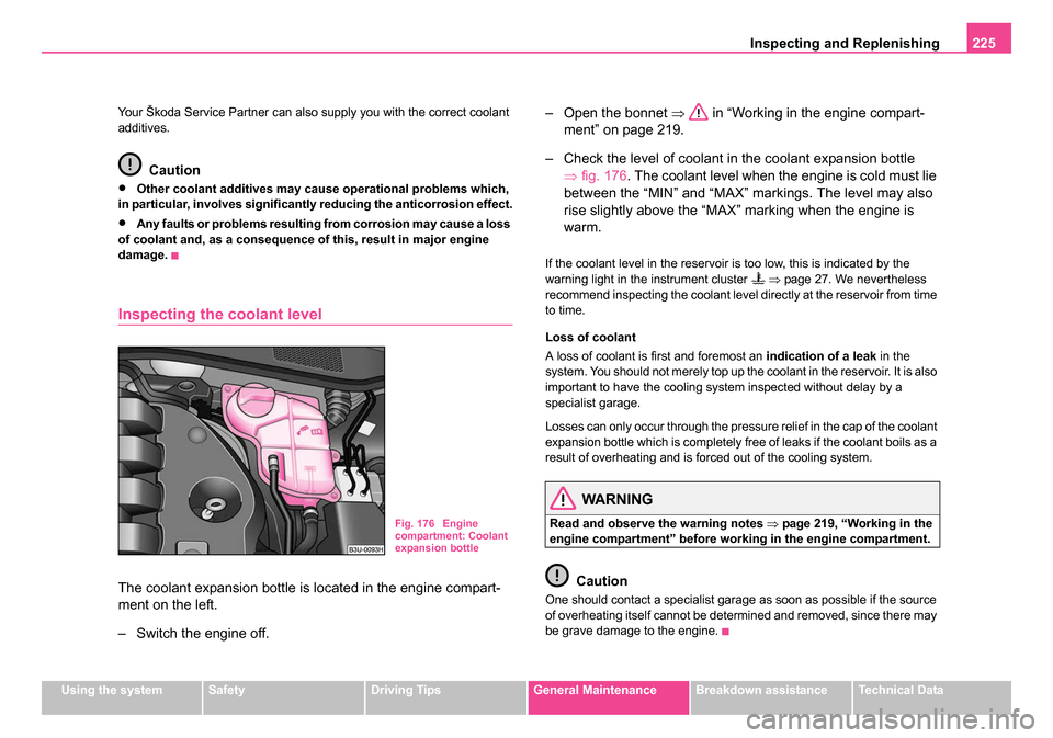
Inspecting the coolant level
The coolant expansion bottle is located in the engine compart-
ment on the left.
– Switch the engine off. – Open the bonnet
⇒ in “Working in the engine compart-
ment” on page 219.
– Check the level of coolant in the coolant expansion bottle ⇒fig. 176. The coolant level when the engine is cold must lie
between the “MIN” and “MAX” markings. The level may also
rise slightly above the “MAX” marking when the engine is
warm.
If the coolant level in the reservoir is too low, this is indicated by the
warning light in the instrument cluster ⇒ page 27. We nevertheless
recommend inspecting the coolant level directly at the reservoir from time
to time.
Loss of coolant
A loss of coolant is first and foremost an indication of a leak in the
system. You should not merely top up the coolant in the reservoir. It is also
important to have the cooling system inspected without delay by a
specialist garage.
Losses can only occur through the pressure relief in the cap of the coolant
expansion bottle which is completely free of leaks if the coolant boils as a
result of overheating and is forced out of the cooling system.
WARNING
Read and observe the warning notes ⇒page 219, “Working in the
engine compartment” before working in the engine compartment.
Caution
One should contact a specialist garage as soon as possible if the source
of overheating itself cannot be determined and removed, since there may
be grave damage to the engine.
Fig. 176 Engine
compartment: Coolant
expansion bottle
NKO B5 20.book Page 225 Monday, July 3, 2006 2:09 PM
Page 228 of 281

Inspecting and Replenishing227
Using the systemSafetyDriving TipsGeneral MaintenanceBreakdown assistanceTechnical Data
The radiator fan may continue running for up to 10 minutes after the
engine has been switched off - even if the ignition is also off. It may also
switch on suddenly after a certain time, if
•the coolant temperature has risen because of an accumulation of heat
or
•the warm engine compartment is heated up additionally by strong
sunlight.
WARNING
You must therefore be aware when working in the engine compart-
ment that the fan may switch on suddenly - risk of injury!
Brake fluid
Inspecting the brake fluid level
You can also see the location of the brake fluid reservoir in the
engine compartment from the general view of the engine
compartment ⇒page 220. The brake fluid reservoir on right-
hand steering models is positioned on the other side of the
engine compartment.
– Switch the engine off.
– Open the bonnet ⇒ in “Working in the engine compart-
ment” on page 219.
– Pull off the rubber seal ⇒fig. 177 partially away and lift the
cover slightly.
– Inspect the brake fluid level at the reservoir . The level must be between the “MIN” and “MAX” markings. The markings are
indicated on the side of the reservoir.
A slight drop in the fluid level results when driving due to normal wear-and-
tear and automatic adjustment of the brake pads, and is perfectly normal.
There may be an indication of a leak in the brake system, however, if the
fluid level drops significantly within a short time or if it drops below the
“MIN” marking. A situation where the brake fluid level is too low is indi-
cated by the warning light
lighting up in the instrument cluster
⇒ page 36. In this case stop the car immediately and do not drive any
further! Contact a Škoda Dealer to obtain professional assistance.
WARNING
•Read and observe the warning notes ⇒page 219, “Working in
the engine compartment” before working in the engine compart-
ment.
Fig. 177 Engine
compartment: Brake
fluid reservoir
AB
AC
AA
NKO B5 20.book Page 227 Monday, July 3, 2006 2:09 PM
Page 262 of 281
Fuses and light bulbs261
Using the systemSafetyDriving TipsGeneral MaintenanceBreakdown assistanceTechnical Data
Caution
•Never attempt to “repair” fuses and also do not replace them with a
fuse of a higher amperage - risk of fire! This may also cause damage at
another part of the electrical system.
•Have the electrical system checked as quickly as possible by a
specialist garage if a newly inserted fuse blows again after a short time.
Note
We recommend that you have these fuses replaced by a specialist
garage.
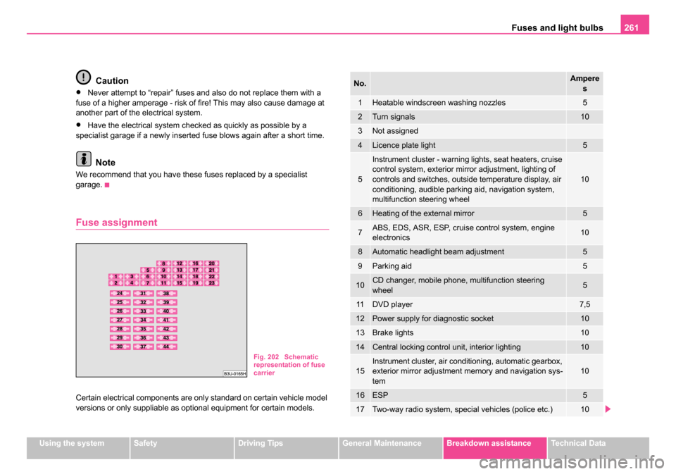
Fuse assignment
Certain electrical components are only standard on certain vehicle model
versions or only suppliable as optional equipment for certain models.
Fig. 202 Schematic
representation of fuse
carrier
No.Ampere
s
1Heatable windscreen washing nozzles5
2Turn signals10
3Not assigned
4Licence plate light5
5
Instrument cluster - warning lights, seat heaters, cruise
control system, exterior mirror adjustment, lighting of
controls and switches, outside temperature display, air
conditioning, audible parking aid, navigation system,
multifunction steering wheel
10
6Heating of the external mirror5
7ABS, EDS, ASR, ESP, cruise control system, engine
electronics10
8Automatic headlight beam adjustment5
9Parking aid5
10CD changer, mobile phone, multifunction steering
wheel5
11DVD player7,5
12Power supply for diagnostic socket10
13Brake lights10
14Central locking control unit, interior lighting10
15Instrument cluster, air conditioning, automatic gearbox,
exterior mirror adjustment memory and navigation sys-
tem10
16ESP5
17Two-way radio system, special vehicles (police etc.)10
NKO B5 20.book Page 261 Monday, July 3, 2006 2:09 PM
Page 275 of 281
Index
274
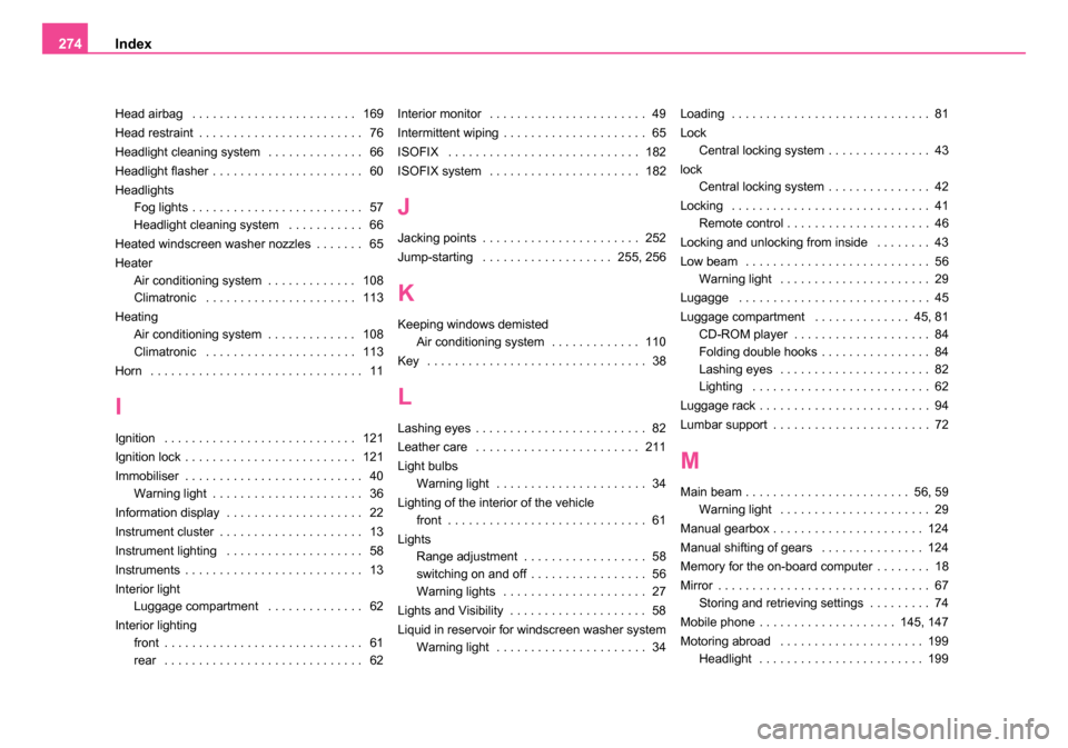
Head airbag . . . . . . . . . . . . . . . . . . . . . . . . 169
Head restraint . . . . . . . . . . . . . . . . . . . . . . . . 76
Headlight cleaning system . . . . . . . . . . . . . . 66
Headlight flasher . . . . . . . . . . . . . . . . . . . . . . 60
Headlights
Fog lights . . . . . . . . . . . . . . . . . . . . . . . . . 57
Headlight cleaning system . . . . . . . . . . . 66
Heated windscreen washer nozzles . . . . . . . 65
Heater Air conditioning system . . . . . . . . . . . . . 108
Climatronic . . . . . . . . . . . . . . . . . . . . . . 113
Heating Air conditioning system . . . . . . . . . . . . . 108
Climatronic . . . . . . . . . . . . . . . . . . . . . . 113
Horn . . . . . . . . . . . . . . . . . . . . . . . . . . . . . . . 11
I
Ignition . . . . . . . . . . . . . . . . . . . . . . . . . . . . 121
Ignition lock . . . . . . . . . . . . . . . . . . . . . . . . . 121
Immobiliser . . . . . . . . . . . . . . . . . . . . . . . . . . 40 Warning light . . . . . . . . . . . . . . . . . . . . . . 36
Information display . . . . . . . . . . . . . . . . . . . . 22
Instrument cluster . . . . . . . . . . . . . . . . . . . . . 13
Instrument lighting . . . . . . . . . . . . . . . . . . . . 58
Instruments . . . . . . . . . . . . . . . . . . . . . . . . . . 13
Interior light Luggage compartment . . . . . . . . . . . . . . 62
Interior lighting front . . . . . . . . . . . . . . . . . . . . . . . . . . . . . 61
rear . . . . . . . . . . . . . . . . . . . . . . . . . . . . . 62 Interior monitor . . . . . . . . . . . . . . . . . . . . . . . 49
Intermittent wiping . . . . . . . . . . . . . . . . . . . . . 65
ISOFIX . . . . . . . . . . . . . . . . . . . . . . . . . . . . 182
ISOFIX system . . . . . . . . . . . . . . . . . . . . . . 182
J
Jacking points . . . . . . . . . . . . . . . . . . . . . . . 252
Jump-starting . . . . . . . . . . . . . . . . . . . 255, 256
K
Keeping windows demisted
Air conditioning system . . . . . . . . . . . . . 110
Key . . . . . . . . . . . . . . . . . . . . . . . . . . . . . . . . 38
L
Lashing eyes . . . . . . . . . . . . . . . . . . . . . . . . . 82
Leather care . . . . . . . . . . . . . . . . . . . . . . . . 211
Light bulbs Warning light . . . . . . . . . . . . . . . . . . . . . . 34
Lighting of the interior of the vehicle front . . . . . . . . . . . . . . . . . . . . . . . . . . . . . 61
Lights Range adjustment . . . . . . . . . . . . . . . . . . 58
switching on and off . . . . . . . . . . . . . . . . . 56
Warning lights . . . . . . . . . . . . . . . . . . . . . 27
Lights and Visibility . . . . . . . . . . . . . . . . . . . . 58
Liquid in reservoir for windscreen washer system Warning light . . . . . . . . . . . . . . . . . . . . . . 34 Loading . . . . . . . . . . . . . . . . . . . . . . . . . . . . . 81
Lock
Central locking system . . . . . . . . . . . . . . . 43
lock Central locking system . . . . . . . . . . . . . . . 42
Locking . . . . . . . . . . . . . . . . . . . . . . . . . . . . . 41 Remote control . . . . . . . . . . . . . . . . . . . . . 46
Locking and unlocking from inside . . . . . . . . 43
Low beam . . . . . . . . . . . . . . . . . . . . . . . . . . . 56 Warning light . . . . . . . . . . . . . . . . . . . . . . 29
Lugagge . . . . . . . . . . . . . . . . . . . . . . . . . . . . 45
Luggage compartment . . . . . . . . . . . . . . 45, 81 CD-ROM player . . . . . . . . . . . . . . . . . . . . 84
Folding double hooks . . . . . . . . . . . . . . . . 84
Lashing eyes . . . . . . . . . . . . . . . . . . . . . . 82
Lighting . . . . . . . . . . . . . . . . . . . . . . . . . . 62
Luggage rack . . . . . . . . . . . . . . . . . . . . . . . . . 94
Lumbar support . . . . . . . . . . . . . . . . . . . . . . . 72
M
Main beam . . . . . . . . . . . . . . . . . . . . . . . . 56, 59 Warning light . . . . . . . . . . . . . . . . . . . . . . 29
Manual gearbox . . . . . . . . . . . . . . . . . . . . . . 124
Manual shifting of gears . . . . . . . . . . . . . . . 124
Memory for the on-board computer . . . . . . . . 18
Mirror . . . . . . . . . . . . . . . . . . . . . . . . . . . . . . . 67 Storing and retrieving settings . . . . . . . . . 74
Mobile phone . . . . . . . . . . . . . . . . . . . . 145, 147
Motoring abroad . . . . . . . . . . . . . . . . . . . . . 199 Headlight . . . . . . . . . . . . . . . . . . . . . . . . 199
NKO B5 20.book Page 274 Monday, July 3, 2006 2:09 PM