navigation system SKODA SUPERB 2006 1.G / (B5/3U) Owner's Manual
[x] Cancel search | Manufacturer: SKODA, Model Year: 2006, Model line: SUPERB, Model: SKODA SUPERB 2006 1.G / (B5/3U)Pages: 281, PDF Size: 12.67 MB
Page 6 of 281
Contents5
Contents
Layout of this Owner's Manual
(explanations)
. . . . . . . . . . . . . . . . . . .
Using the system . . . . . . . . . . . . . . .
Cockpit . . . . . . . . . . . . . . . . . . . . . . . . . . . . . . .
General view . . . . . . . . . . . . . . . . . . . . . . . . .
Instruments and Indicator/Warning LightsGeneral view of the instrument cluster . . . . . .
Engine revolutions counter . . . . . . . . . . . . . . .
Coolant temperature gauge . . . . . . . . . . . . . .
Fuel gauge . . . . . . . . . . . . . . . . . . . . . . . . . . .
Digital clock . . . . . . . . . . . . . . . . . . . . . . . . . .
Speedometer with counter for distance driven
Service Interval Display . . . . . . . . . . . . . . . . .
Multi-functional indicator (onboard computer)
Information display* . . . . . . . . . . . . . . . . . . . .
Auto Check Control . . . . . . . . . . . . . . . . . . . .
Warning lights . . . . . . . . . . . . . . . . . . . . . . . . .
Unlocking and locking . . . . . . . . . . . . . . . . . .
Key . . . . . . . . . . . . . . . . . . . . . . . . . . . . . . . . .
Changing the key battery . . . . . . . . . . . . . . . .
Electronic immobiliser . . . . . . . . . . . . . . .
Child safety lock . . . . . . . . . . . . . . . . . . . . . . .
Central locking system . . . . . . . . . . . . . . . . . .
Remote control . . . . . . . . . . . . . . . . . . . . . . . .
Anti-theft alarm system* . . . . . . . . . . . . . . . . .
Power windows . . . . . . . . . . . . . . . . . . . . . . .
Electric sliding/tilting roof* . . . . . . . . . . . . . . .
Lights and Visibility. . . . . . . . . . . . . . . . . . . . .
Lights . . . . . . . . . . . . . . . . . . . . . . . . . . . . . . .
Interior lighting . . . . . . . . . . . . . . . . . . . . . . . . Visibility . . . . . . . . . . . . . . . . . . . . . . . . . . . . .
Windshield wiper and wash system . . . . . . . .
Rear-view mirror . . . . . . . . . . . . . . . . . . . . . .
Seats and Stowage . . . . . . . . . . . . . . . . . . . .
Front seats . . . . . . . . . . . . . . . . . . . . . . . . . . .
Adjusting front seats manually . . . . . . . . . . . .
Adjusting front seats electrically* . . . . . . . . . .
Front passenger seat with a folding central back
rest* . . . . . . . . . . . . . . . . . . . . . . . . . . . . . . . .
Footrest at the rear* . . . . . . . . . . . . . . . . . . . .
Seat heaters* . . . . . . . . . . . . . . . . . . . . . . . . .
Pedals . . . . . . . . . . . . . . . . . . . . . . . . . . . . . .
Luggage compartment . . . . . . . . . . . . . . . . . .
The cool box behind the armrest of the rear
seats* . . . . . . . . . . . . . . . . . . . . . . . . . . . . . . .
CargoFlex folding box* . . . . . . . . . . . . . . . . . .
The roof luggage rack system . . . . . . . . . . . .
Cup holder . . . . . . . . . . . . . . . . . . . . . . . . . . .
Ashtrays . . . . . . . . . . . . . . . . . . . . . . . . . . . . .
Cigarette lighters and power sockets . . . . . . .
Storage facilities . . . . . . . . . . . . . . . . . . . . . . .
Heating and air conditioning system . . . . .
Air conditioning system . . . . . . . . . . . . . . . . .
Climatronic* (automatic air conditioning) . . . .
Starting-off and Driving. . . . . . . . . . . . . . . . .
Setting steering wheel position . . . . . . . . . . .
Ignition lock . . . . . . . . . . . . . . . . . . . . . . . . . .
Starting the engine . . . . . . . . . . . . . . . . . . . . .
Switching the engine off . . . . . . . . . . . . . . . . .
Shifting (manual gearbox) . . . . . . . . . . . . . . .
Handbrake . . . . . . . . . . . . . . . . . . . . . . . . . . .
Parking aid* . . . . . . . . . . . . . . . . . . . . . . . . . . Front and rear parking aid* . . . . . . . . . . . . . .
Cruise control system (CCS)* . . . . . . . . . . . .
Automatic gearbox*. . . . . . . . . . . . . . . . . . . .
5-speed automatic gearbox . . . . . . . . . . . . . .
Communicating and Navigating . . . . . . . . .
Multifunction steering wheel* . . . . . . . . . . . . .
CD changer* . . . . . . . . . . . . . . . . . . . . . . . . .
Mobile phone, two-way radio system and
navigation system . . . . . . . . . . . . . . . . . . . . .
Safety. . . . . . . . . . . . . . . . . . . . . . . . . . . . . .
Passive Safety . . . . . . . . . . . . . . . . . . . . . . . .
Basic information . . . . . . . . . . . . . . . . . . . . . .
Correct seated position . . . . . . . . . . . . . . . . .
Seat belts. . . . . . . . . . . . . . . . . . . . . . . . . . . . .
Why seat belts? . . . . . . . . . . . . . . . . . . . . . . .
The physical principle of a frontal collision . .
Important safety information regarding the use
of seat belts . . . . . . . . . . . . . . . . . . . . . . . . . .
How are seat belts correctly fastened? . . . . .
Belt tensioners . . . . . . . . . . . . . . . . . . . . . . . .
Airbag system. . . . . . . . . . . . . . . . . . . . . . . . .
Description of the airbag system . . . . . . . . . .
Front airbag . . . . . . . . . . . . . . . . . . . . . . . . . .
Side airbag . . . . . . . . . . . . . . . . . . . . . . . . . .
Head airbags* . . . . . . . . . . . . . . . . . . . . . . . .
Deactivating an airbag . . . . . . . . . . . . . . . . . .
8
9
11
11
13
13
14
14
15
15
16
16
18
22
24
27
38
38
39
40
40
41
46
48
49
52
56
56
61 63
65
67
71
71
72
73
78
79
80
81
81
88
91
94
96
97
99
101
108
108 11 3
120
120
121
122
123
124
125
126 127
128
131
131
137
137
141
145
149
149
149
151
155
155
156
157
158
160
162
162
164
166
169
171
NKO B5 20.book Page 5 Monday, July 3, 2006 2:09 PM
Page 12 of 281
Cockpit11
Using the systemSafetyDriving TipsGeneral MaintenanceBreakdown assistanceTechnical Data
Cockpit
General view
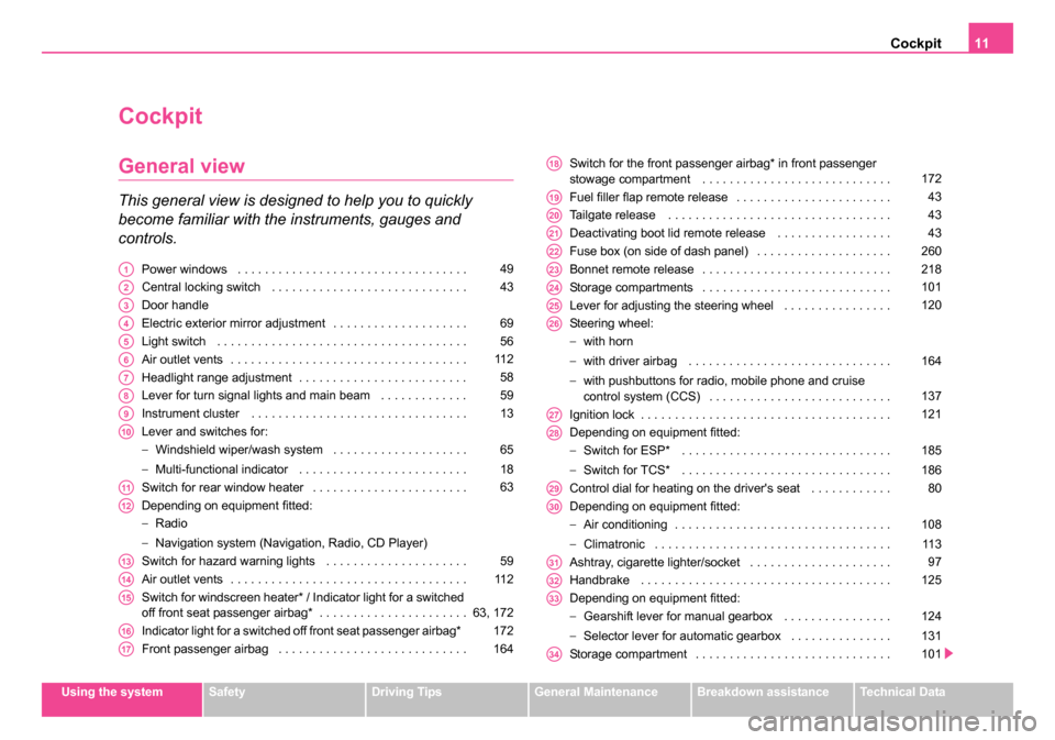
This general view is designed to help you to quickly
become familiar with the instruments, gauges and
controls.
Power windows . . . . . . . . . . . . . . . . . . . . . . . . . . . . . . . . . .
Central locking switch . . . . . . . . . . . . . . . . . . . . . . . . . . . . .
Door handle
Electric exterior mirror adjustment . . . . . . . . . . . . . . . . . . . .
Light switch . . . . . . . . . . . . . . . . . . . . . . . . . . . . . . . . . . . . .
Air outlet vents . . . . . . . . . . . . . . . . . . . . . . . . . . . . . . . . . . .
Headlight range adjustment . . . . . . . . . . . . . . . . . . . . . . . . .
Lever for turn signal lights and main beam . . . . . . . . . . . . .
Instrument cluster . . . . . . . . . . . . . . . . . . . . . . . . . . . . . . . .
Lever and switches for:
−Windshield wiper/wash system . . . . . . . . . . . . . . . . . . . .
− Multi-functional indicator . . . . . . . . . . . . . . . . . . . . . . . . .
Switch for rear window heater . . . . . . . . . . . . . . . . . . . . . . .
Depending on equipment fitted:
− Radio
− Navigation system (Navigation, Radio, CD Player)
Switch for hazard warning lights . . . . . . . . . . . . . . . . . . . . .
Air outlet vents . . . . . . . . . . . . . . . . . . . . . . . . . . . . . . . . . . .
Switch for windscreen heater* / Indicator light for a switched
off front seat passenger airbag* . . . . . . . . . . . . . . . . . . . . . .
Indicator light for a switched off front seat passenger airbag*
Front passenger airbag . . . . . . . . . . . . . . . . . . . . . . . . . . . . Switch for the front passenger airbag* in front passenger
stowage compartment . . . . . . . . . . . . . . . . . . . . . . . . . . . .
Fuel filler flap remote release . . . . . . . . . . . . . . . . . . . . . . .
Tailgate release . . . . . . . . . . . . . . . . . . . . . . . . . . . . . . . . .
Deactivating boot lid remote release . . . . . . . . . . . . . . . . .
Fuse box (on side of dash panel) . . . . . . . . . . . . . . . . . . . .
Bonnet remote release . . . . . . . . . . . . . . . . . . . . . . . . . . . .
Storage compartments . . . . . . . . . . . . . . . . . . . . . . . . . . . .
Lever for adjusting the steering wheel . . . . . . . . . . . . . . . .
Steering wheel:
−
with horn
− with driver airbag . . . . . . . . . . . . . . . . . . . . . . . . . . . . . .
− with pushbuttons for radio, mobile phone and cruise
control system (CCS) . . . . . . . . . . . . . . . . . . . . . . . . . . .
Ignition lock . . . . . . . . . . . . . . . . . . . . . . . . . . . . . . . . . . . . .
Depending on equipment fitted:
− Switch for ESP* . . . . . . . . . . . . . . . . . . . . . . . . . . . . . . .
− Switch for TCS* . . . . . . . . . . . . . . . . . . . . . . . . . . . . . . .
Control dial for heating on the driver's seat . . . . . . . . . . . .
Depending on equipment fitted:
− Air conditioning . . . . . . . . . . . . . . . . . . . . . . . . . . . . . . . .
− Climatronic . . . . . . . . . . . . . . . . . . . . . . . . . . . . . . . . . . .
Ashtray, cigarette lighter/socket . . . . . . . . . . . . . . . . . . . . .
Handbrake . . . . . . . . . . . . . . . . . . . . . . . . . . . . . . . . . . . . .
Depending on equipment fitted:
− Gearshift lever for manual gearbox . . . . . . . . . . . . . . . .
− Selector lever for automatic gearbox . . . . . . . . . . . . . . .
Storage compartment . . . . . . . . . . . . . . . . . . . . . . . . . . . . . A149
A243
A3
A469
A556
A611 2
A758
A859
A913
A10
65
18
A1163
A12
A1359
A1411 2
A1563, 172
A16172
A17164
A18172
A1943
A2043
A2143
A22260
A23218
A24101
A25120
A26
164
137
A27121
A28
185
186
A2980
A30
108
11 3
A3197
A32125
A33
124
131
A34101
NKO B5 20.book Page 11 Monday, July 3, 2006 2:09 PM
Page 13 of 281
Cockpit
12
Control dial for heating on the front passenger seat . . . . . .
Lockable storage compartment on the front passenger side
Note
•Equipment which is marked * is only standard on certain vehicle model
versions or only suppliable as optional equipment for certain models.
•Vehicles with factory-fitted radio, mobile phone, navigation system, CD
player etc. are supplied with separate instructions for operating such
equipment.
•The arrangement of the controls and switches and the location of
some items on right-hand drive models may differ from that shown in
⇒ page 10, fig. 1 . The symbols on the controls and switches are the same
as for left-hand drive models.
A3580A36101
NKO B5 20.book Page 12 Monday, July 3, 2006 2:09 PM
Page 23 of 281
Instruments and Indicator/Warning Lights
22
Information display*
Introduction
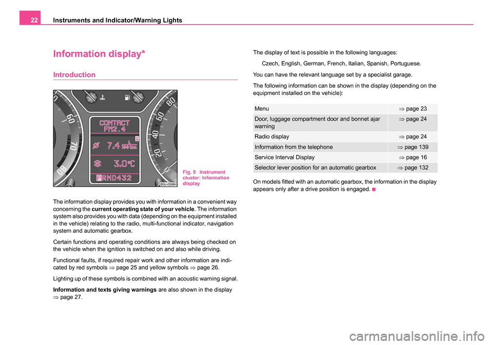
The information display provides you with information in a convenient way
concerning the current operating state of your vehicle . The information
system also provides you with data (depending on the equipment installed
in the vehicle) relating to the radio, multi-functional indicator, navigation
system and automatic gearbox.
Certain functions and operating conditions are always being checked on
the vehicle when the ignition is switched on and also while driving.
Functional faults, if required repair work and other information are indi-
cated by red symbols ⇒page 25 and yellow symbols ⇒page 26.
Lighting up of these symbols is combined with an acoustic warning signal.
Information and texts giving warnings are also shown in the display
⇒ page 27. The display of text is possible in the following languages:
Czech, English, German, French, Italian, Spanish, Portuguese.
You can have the relevant language set by a specialist garage.
The following information can be shown in the display (depending on the
equipment installed on the vehicle):
On models fitted with an automatic gearbox, the information in the display
appears only after a drive position is engaged.
Fig. 9 Instrument
cluster: Information
display
Menu⇒ page 23
Door, luggage compartment door and bonnet ajar
warning⇒page 24
Radio display⇒page 24
Information from the telephone⇒page 139
Service Interval Display⇒page 16
Selector lever position for an automatic gearbox⇒page 132
NKO B5 20.book Page 22 Monday, July 3, 2006 2:09 PM
Page 24 of 281
Instruments and Indicator/Warning Lights23
Using the systemSafetyDriving TipsGeneral MaintenanceBreakdown assistanceTechnical Data
Menu
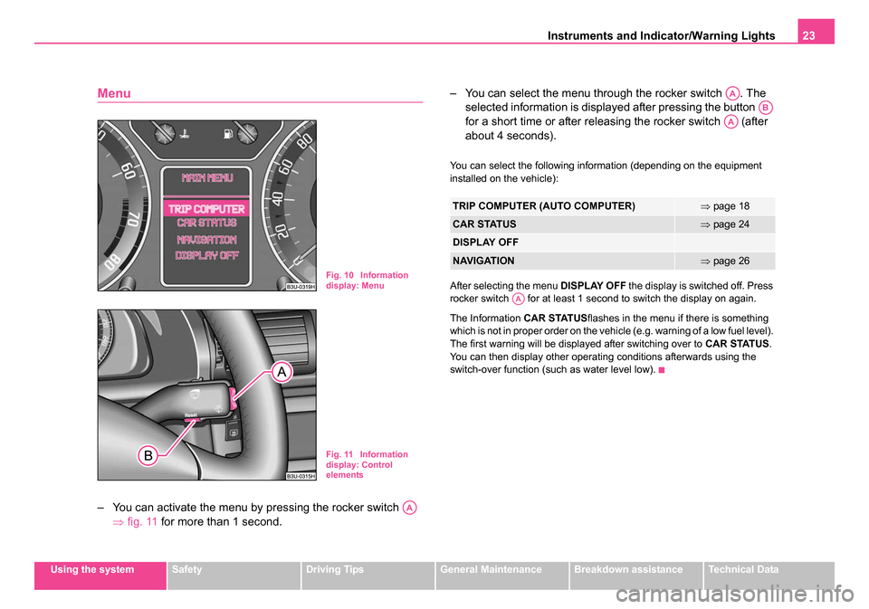
– You can activate the menu by pressing the rocker switch
⇒fig. 11 for more than 1 second. – You can select the menu through the rocker switch . The
selected information is displayed after pressing the button
for a short time or after releasing the rocker switch (after
about 4 seconds).
You can select the following information (depending on the equipment
installed on the vehicle):
After selecting the menu DISPLAY OFF the display is switched off. Press
rocker switch for at least 1 second to switch the display on again.
The Information CAR STATUSflashes in the menu if there is something
which is not in proper order on the vehicle (e.g. warning of a low fuel level).
The first warning will be displayed after switching over to CAR STATUS.
You can then display other operating conditions afterwards using the
switch-over function (such as water level low).
Fig. 10 Information
display: Menu
Fig. 11 Information
display: Control
elements
AA
TRIP COMPUTER (AUTO COMPUTER)⇒ page 18
CAR STATUS⇒page 24
DISPLAY OFF
NAVIGATION⇒page 26
AA
AB
AA
AA
NKO B5 20.book Page 23 Monday, July 3, 2006 2:09 PM
Page 27 of 281
Instruments and Indicator/Warning Lights
26
Meaning of the red symbols:
Three successive warning signals will sound if a red symbol appears. The
symbol continues flashing until the fault is rectified.
If several operational faults of priority 1 exist, the symbols appear one after
the other and are each illuminated for about 2 seconds.
Yellow symbols
A yellow symbol signals a warning.
The meaning of the yellow symbols:
One warning signal will sound if a yellow symbol appears.
If several operational faults of priority 2 exist, the symbols appear one after
the other and are each illuminated for about 2 seconds.
Check the relevant function as soon as possible.
Navigation system*
The controls for the navigation system, radio, CD player are located in the
centre console on both sides of the monitor screen. Navigation data is
also shown in the information display of the instrument cluster.
Information and warning texts are displayed preferentially when the navi-
gation system is switched on.
Operation of the navigation system is described in separate operating
instructions to be found in the on-board literature.
Faults in the brake surface⇒ page 36
Coolant level too low/coolant tempera-
ture too high⇒page 32
Engine oil pressure too low⇒page 33
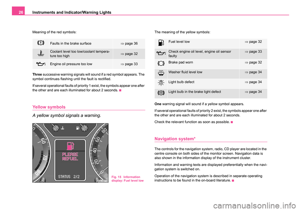
Fig. 15 Information
display: Fuel level low
Fuel level low⇒page 32
Check engine oil level, engine oil sensor
faulty⇒page 33
Brake pad worn⇒page 32
Washer fluid level low⇒page 34
Light bulb defect⇒page 34
Light bulb in the brake light defect⇒page 34
NKO B5 20.book Page 26 Monday, July 3, 2006 2:09 PM
Page 142 of 281

Communicating and Navigating141
Using the systemSafetyDriving TipsGeneral MaintenanceBreakdown assistanceTechnical Data
CD changer*
Take out and insert CD magazine
The CD changer for the radio and navigation system is located in
the left side compartment of the luggage compartment.
Take magazine out of the changer
– Open safety stop ⇒fig. 129 fully.
– Press button . The magazine is automatically ejected.
– Take out the magazine.
Insert magazine into the changer
– Insert the magazine with the arrow of the illustration upwards up to the stop ⇒page 142, fig. 130 . The tip of the arrow on the
magazine must point at the same time to the magazine box. – Slide safety stop closed.
After inserting the magazine, it is analysed how many CDs are in the
magazine.
If there is no magazine in the changer,
NO CD MAGAZINE is displayed in
the CD-mode on the display of the radio.
You can also take out the magazine when the radio is switched off.
Caution
Always close the safety cover after inserting the magazine. The safety
cover protects the CD-changer from dirt and dust particles penetrating into
the CD-changer, in order to avoid operational faults.
Note
•Described in this Owner's Manual are only the steps required for the
operation of the CD-changer.
•You will find further information for this setting menu in the Radio
Owner's Manual.
•Only Use CD-magazines from Škoda Original Accessories.
Fig. 129 The CD
changer
A1
A3A2
NKO B5 20.book Page 141 Monday, July 3, 2006 2:09 PM
Page 146 of 281

Communicating and Navigating145
Using the systemSafetyDriving TipsGeneral MaintenanceBreakdown assistanceTechnical Data
Mobile phone, two-way radio system and
navigation system
Universal telephone connection at the front* (GSM II)
A telephone mount is factory-fitted. The mount is attached to the
centre console. Adapter (Cullmann) and mobile phone are not
factory-fitted by Škoda Auto.
Initialisation
– Withdraw the ignition key.
– First insert the adapter without the mobile phone into the
mount in the direction of arrow ⇒fig. 133 until the
adapter is touching the stop. Press the adapter slightly in the
direction of arrow until it locks into position. – Plug the adapter cable into the mobile phone socket. The
socket is located on the mobile phone mount below.
– Switch on the ignition.
– Wait approximately 20 seconds, switch off the ignition and pull the ignition key out of the ignition lock.
– Insert the mobile phone into the adapter (as specified in manufacturer's instructions) and switch on the ignition.
Removing the mobile phone and adapter
– Press the button and remove the mobile telephone.
An initialisation must be carried out:
•after the first connection of the adapter,
•after reconnecting the battery,
•after pulling out the adapter cable from the power socket for the mobile
phone.
This enables you to make full use of the advantages of a normal carphone
(“handsfree system” using a microphone integrated in the vehicle, optimal
transmission of signals using an external aerial etc.). The battery of the
mobile phone is also constantly charged.
Please contact your Škoda Service Partner if there are any points which
are not clear.
Please also refer to the additional instructions ⇒page 147, “Mobile
phones and two-way radio systems”.Fig. 133 Universal
telephone connection
at the front
ABA1
A2
AA
AC
NKO B5 20.book Page 145 Monday, July 3, 2006 2:09 PM
Page 148 of 281

Communicating and Navigating147
Using the systemSafetyDriving TipsGeneral MaintenanceBreakdown assistanceTechnical Data
Note
For technical reasons it is not possible to use simultaneously the front and
rear mobile phone. Ensure that the adapter is always inserted only in
the bracket .
Mobile phones and two-way radio systems
The installation of a mobile phone and two-way radio system in a vehicle
should only be carried out by a Škoda Dealer.
Škoda Auto a.s. permits the operation of mobile phones and two-way
radio systems with a professionally installed external aerial and a
maximum transmission power of up to 10 watts.
Our specialist garage is also happy to inform you about the possibilities
available for installing and operating mobile telephones and radio trans-
mitters which have an output greater than 10 watts. The Škoda Service
Partners can provide you with details about the technical possibilities for
retrofitting of mobile telephones and radio transmitters.
The operation of commercially available mobile phones or two-way radio
systems may cause operational problems in the electronic systems of
your car. The reasons for this may be:
•no external aerial,
•external aerial incorrectly installed,
•transmission power greater than 10 watts.
You should therefore not operate a mobile phone or two-way radio
system inside the vehicle without the use of an external aerial, or with
an external aerial which has been incorrectly installed.
You should also be aware of the fact that only an external aerial makes it
possible to achieve the optimal range of such equipment.
WARNING
•If a mobile phone or two-way radio system is operated inside the
vehicle without using an external aerial, or with an external aerial
which has been incorrectly installed, the result can be excessive
electromagnetic fields which may cause harm to your health.
•Please always pay full attention to the traffic situation around
you!
•You must not install two-way radio systems, mobile phones or
mounts on the covers of the airbags or within the immediate
deployment range of airbags. This might result in injuries to the
occupants in the event of an accident!
Note
Please also refer to the operating instructions of the mobile phones and
two-way radio systems.
Navigation system*
The controls for the navigation system, radio, CD player are located in the
centre console on both sides of the monitor screen. Navigation data is
also shown in the information display.
Please refer to the relevant operating instructions for a detailed descrip-
tion of the navigation system.
AAAB
NKO B5 20.book Page 147 Monday, July 3, 2006 2:09 PM
Page 262 of 281
Fuses and light bulbs261
Using the systemSafetyDriving TipsGeneral MaintenanceBreakdown assistanceTechnical Data
Caution
•Never attempt to “repair” fuses and also do not replace them with a
fuse of a higher amperage - risk of fire! This may also cause damage at
another part of the electrical system.
•Have the electrical system checked as quickly as possible by a
specialist garage if a newly inserted fuse blows again after a short time.
Note
We recommend that you have these fuses replaced by a specialist
garage.
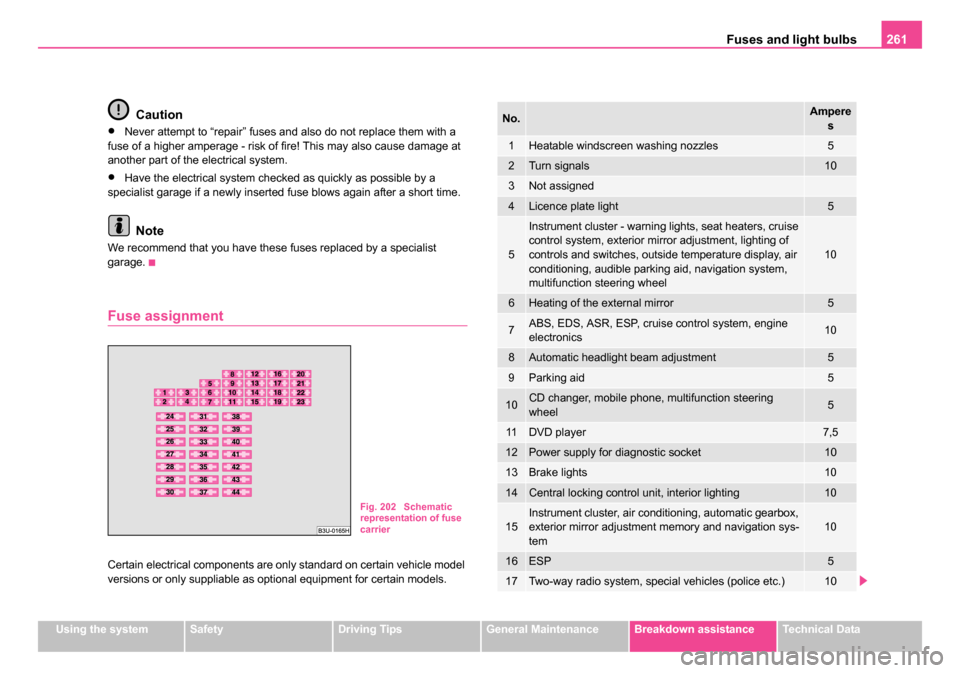
Fuse assignment
Certain electrical components are only standard on certain vehicle model
versions or only suppliable as optional equipment for certain models.
Fig. 202 Schematic
representation of fuse
carrier
No.Ampere
s
1Heatable windscreen washing nozzles5
2Turn signals10
3Not assigned
4Licence plate light5
5
Instrument cluster - warning lights, seat heaters, cruise
control system, exterior mirror adjustment, lighting of
controls and switches, outside temperature display, air
conditioning, audible parking aid, navigation system,
multifunction steering wheel
10
6Heating of the external mirror5
7ABS, EDS, ASR, ESP, cruise control system, engine
electronics10
8Automatic headlight beam adjustment5
9Parking aid5
10CD changer, mobile phone, multifunction steering
wheel5
11DVD player7,5
12Power supply for diagnostic socket10
13Brake lights10
14Central locking control unit, interior lighting10
15Instrument cluster, air conditioning, automatic gearbox,
exterior mirror adjustment memory and navigation sys-
tem10
16ESP5
17Two-way radio system, special vehicles (police etc.)10
NKO B5 20.book Page 261 Monday, July 3, 2006 2:09 PM