service interval reset SKODA SUPERB 2007 1.G / (B5/3U) Owner's Manual
[x] Cancel search | Manufacturer: SKODA, Model Year: 2007, Model line: SUPERB, Model: SKODA SUPERB 2007 1.G / (B5/3U)Pages: 259, PDF Size: 14.71 MB
Page 15 of 259

Instruments and Indicator/Warning Lights
14
WARNING
Never seek to adjust the trip counter for distance driven while driving for
safety reasons!
Service Interval Display
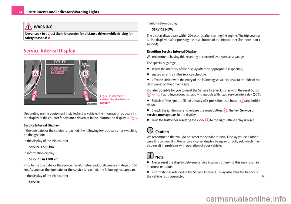
Depending on the equipment installed in the vehicle, the information appears in
the display of the counter for distance driven or in the information display ⇒fig. 5 .
Service Interval Display
If the due date for the service is reached, the following text appears after switching
on the ignition:
in the display of the trip counter Service 1 500 km
in information display SERVICE in 1500 km
Prior to the due date for the service the kilometre readout decreases in steps of 100
km. As soon as the due date for the service is reached, the following text appears:
in the display of the trip counter Service in information display
SERVICE NOW
The display disappears within 20 seconds after starting the engine. The trip counter
is also displayed after pressing the reset bu tton of the trip counter (for more than 1
second).
Resetting Service Interval Display
We recommend having this resetting performed by a specialist garage.
The specialist garage:
•resets the memory of the display after the appropriate inspection,
•makes an entry in the Service schedule,
•affix the sticker with the entry of the following service interval to the side of the
dash panel on the driver's side.
It is also possible for you to reset the Se rvice Interval Display with the reset button
⇒ fig. 5 as follows (does not apply to models with fixed service intervals - QG2).
•Switch off the ignition (if not already of f), press the reset button and hold it
down.
•Switch the ignition on and release the reset button . The text Service or
service now appears in the display.
•Turn the button for resetting the clock to the right - the display is reset.
Caution
We recommend that you do not reset the Service Interval Display yourself other-
wise this can result in the service interval display being incorrectly set, which may
also result in problems with operation of your vehicle.
Note
•Never reset the display between service intervals otherwise this may result in
incorrect readouts.
•information is retained in the Service Interval Display also after the battery of
the vehicle is disconnected.
Fig. 5 Instrument
cluster: Service Interval
DisplayAB
AB
AB
AA
NKO B5 20.book Page 14 Friday, March 2, 2007 1:46 PM
Page 16 of 259

Instruments and Indicator/Warning Lights15
Using the systemSafetyDriving TipsGeneral MaintenanceBreakdown assistanceTechnical Data
•it is necessary to re-code the Service Interval Display if a new instrument cluster
is installed during repair work. This work is carried out by a specialist garage.
•After resetting the display with flexible service intervals (QG1) using the reset
button , the data displayed are the same as for a car with fixed service intervals
(QG2). We therefore recommend having the Service Interval Display reset only by a
Škoda Service Partner who is familiar with the procedure for resetting the display
with a vehicle system tester.
•Please refer to the brochure Service sc hedule for extensive information about
the service intervals.
Multi-functional indicator (onboard computer)
Introduction
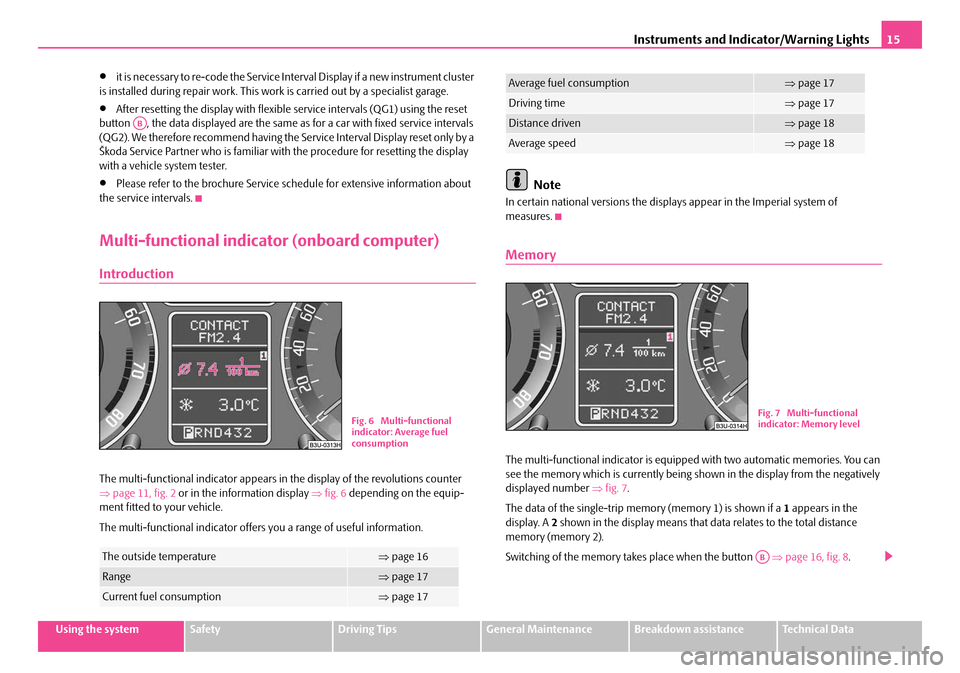
The multi-functional indicator appears in the display of the revolutions counter
⇒ page 11, fig. 2 or in the information display ⇒fig. 6 depending on the equip-
ment fitted to your vehicle.
The multi-functional indicator offers you a range of useful information.
Note
In certain national versions the displays appear in the Imperial system of
measures.
Memory
The multi-functional indicator is equippe d with two automatic memories. You can
see the memory which is currently being shown in the display from the negatively
displayed number ⇒fig. 7 .
The data of the single-trip memo ry (memory 1) is shown if a 1 appears in the
display. A 2 shown in the display means that da ta relates to the total distance
memory (memory 2).
Switching of the memory takes place when the button ⇒page 16, fig. 8 .
The outside temperature⇒page 16
Range⇒page 17
Current fuel consumption⇒page 17
AB
Fig. 6 Multi-functional
indicator: Average fuel
consumption
Average fuel consumption⇒page 17
Driving time⇒page 17
Distance driven⇒page 18
Average speed⇒page 18
Fig. 7 Multi-functional
indicator: Memory level
AB
NKO B5 20.book Page 15 Friday, March 2, 2007 1:46 PM