tow bar SKODA SUPERB 2007 1.G / (B5/3U) Owner's Manual
[x] Cancel search | Manufacturer: SKODA, Model Year: 2007, Model line: SUPERB, Model: SKODA SUPERB 2007 1.G / (B5/3U)Pages: 259, PDF Size: 14.71 MB
Page 61 of 259
Seats and Stowage
60
Adjusting height of seat
– Lift the seat if required by pulling or pumping lever ⇒page 59,
fig. 53 upwards.
– Lower the seat if required by pushing or pumping lever down- wards.
Adjust the angle of the seat backrest
– Relieve any pressure on the backrest (do not lean on it) and turn the handwheel to adjust the angle of the backrest.
Adjusting Lumbar support
– Turn the handwheel until you have set the most comfortable curvature of the seat upholstery in the area of your spine.
The driver's seat should be adjusted in such a way that the pedals can be pressed
to the floor with slightly bent legs.
The backrest on the driver's seat should be adjusted in such a way that the upper
point of the steering wheel can be easi ly reached with slightly bent arms.
WARNING
•Only adjust the driver seat when the ve hicle is stationary - risk of injury!
•Take care when adjusting the seat! Adjusting the seat without care can
lead to bruises or injuries.
•The backrests must not be angled too far back when driving otherwise
this will affect proper operation of th e seat belts and of the airbag system -
risk of injury!
Adjusting front seats electrically*
Adjusting seats
Adjusting seat
– Adopt the correct seated position ⇒page 59.
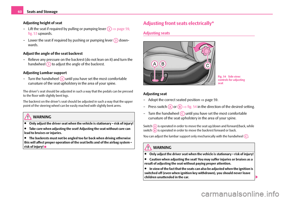
– Press switch or ⇒fig. 54 in the direction of the desired setting.
– Turn the handwheel until you have set the most comfortable curvature of the seat upholstery in the area of your spine.
Switch is operated in order to move the seat up/down and forward/back, while
switch is operated in order to move the backrest forward or back.
You can adjust the lumbar support only mechanically with the handwheel .
WARNING
•Only adjust the driver seat when the vehicle is stationary - risk of injury!
•Caution when adjusting the seat! You ma y suffer injuries or bruises as a
result of adjusting the seat without paying proper attention.
•In view of the fact that the seats can also be adjusted when the ignition is
switched off (even when ignition key withdrawn), you should never leave
children unattended in the car.
A2
A2
A3
A4
B1Z-0042HB1Z-0042H
Fig. 54 Side view:
controls for adjusting
seat
AAAB
AC
AAAB
AC
NKO B5 20.book Page 60 Friday, March 2, 2007 1:46 PM
Page 78 of 259
Seats and Stowage77
Using the systemSafetyDriving TipsGeneral MaintenanceBreakdown assistanceTechnical Data
Lowering folding box
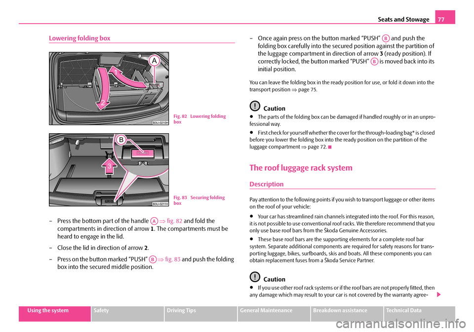
– Press the bottom part of the handle ⇒fig. 82 and fold the
compartments in direction of arrow 1. The compartments must be
heard to engage in the lid.
– Close the lid in direction of arrow 2.
– Press on the button marked “PUSH” ⇒fig. 83 and push the folding
box into the secured middle position. – Once again press on the button marked “PUSH” and push the
folding box carefully into the secured position against the partition of
the luggage compartment in direction of arrow 3 (ready position). If
correctly locked, the button marked “PUSH” is moved back into its
initial position.
You can leave the folding box in the ready position for use, or fold it down into the
transport position ⇒page 75.
Caution
•The parts of the folding box can be dama ged if handled roughly or in an unpro-
fessional way.
•First check for yourself whether the cover for the through-loading bag* is closed
before you lower the folding box into the ready position on the partition of the
luggage compartment ⇒page 72.
The roof luggage rack system
Description
Pay attention to the following points if yo u wish to transport luggage or other items
on the roof of your vehicle:
•Your car has streamlined rain channels in tegrated into the roof. For this reason,
it is not possible to use conventional r oof racks. We therefore recommend that you
only use base roof bars from the Škoda Genuine Accessories.
•These base roof bars are the supporti ng elements for a complete roof bar
system. Separate additional components are required for safety reasons for trans-
porting luggage, bikes, surfboards, skis and boats. All these components you can
obtain replacement fuses from a Škoda Service Partner.
Caution
•If you use other roof rack sy stems or if the roof bars are not properly fitted, then
any damage which may result to your ca r is not covered by the warranty agree-
B1Z-0042HB1Z-0042HFig. 82 Lowering folding
box
B1Z-0042HB1Z-0042HFig. 83 Securing folding
box
AA
AB
AB
AB
NKO B5 20.book Page 77 Friday, March 2, 2007 1:46 PM
Page 79 of 259
Seats and Stowage
78
ments. It is therefore essential to pay a ttention to the fitting instructions supplied
with the roof luggage rack system.
•On models fitted with a power sliding/tilting roof, ensure that the opened
sliding/tilting roof does not strike any items of luggage transported on the roof.
For the sake of the environment
The increased aerodynamic drag results in a higher fuel consumption. One should
therefore take off the roof bar system after use.
Attachment points
Fitting
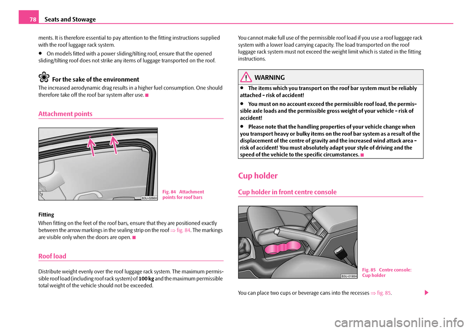
When fitting on the feet of the roof bars, ensure that they are positioned exactly
between the arrow markings in the sealing strip on the roof ⇒fig. 84 . The markings
are visible only when the doors are open.
Roof load
Distribute weight evenly over the roof luggage rack system. The maximum permis-
sible roof load (including roof rack system) of 100 kg and the maximum permissible
total weight of the vehicl e should not be exceeded. You cannot make full use of the permissible
roof load if you use a roof luggage rack
system with a lower load carrying capa city. The load transported on the roof
luggage rack system must not exceed the weight limit which is stated in the fitting
instructions.
WARNING
•The items which you transport on the roof bar system must be reliably
attached - risk of accident!
•You must on no account exceed the permissible roof load, the permis-
sible axle loads and the permissible gros s weight of your vehicle - risk of
accident!
•Please note that the handling prop erties of your vehicle change when
you transport heavy or bulky items on the roof bar system as a result of the
displacement of the centre of gravity and the increased wind attack area -
risk of accident! You must absolutely adapt your style of driving and the
speed of the vehicle to the specific circumstances.
Cup holder
Cup holder in front centre console
You can place two cups or beverage cans into the recesses ⇒fig. 85 .
Fig. 84 Attachment
points for roof bars
B1Z-0042HB1Z-0042HFig. 85 Centre console:
Cup holder
NKO B5 20.book Page 78 Friday, March 2, 2007 1:46 PM
Page 106 of 259
Starting-off and Driving105
Using the systemSafetyDriving TipsGeneral MaintenanceBreakdown assistanceTechnical Data
WARNING
•The parking aid is not a substitute fo r the driver paying proper attention
and it is always the driver's responsibility to take care when parking the
vehicle or carrying out similar manoeuvres.
•You should therefore satisfy yourself, before reversing, that there is no
small obstacle, such as a rock, thin po st, trailer drawbar etc., behind your
vehicle. Such an obstacle might not be within the range detected by the
sensors.
Note
•The parking aid does not operate if you are towing a trailer (applies to models
which feature a factory-fitted towing device*).
•If a warning signal sounds for about 3 se conds after switching the ignition on
and engaging reverse gear, and there is no obstacle close to your car, this indicates
a system fault. Have the fault rectified by a specialist workshop.
•The sensors must be kept clean and free of ice to enable the parking aid to
operate properly.
Front and rear parking aid*
The parking aid provides a warning of obstacles in front and behind
the vehicle.
The audible parking aid determines the dist ance between the front or rear bumper
and an obstacle with the aid of ultrasound sensors. The sensors are integrated in the
front and rear bumper. The signal tones for the front parking aid sound lower than
for the rear parking aid.
Range of sensors
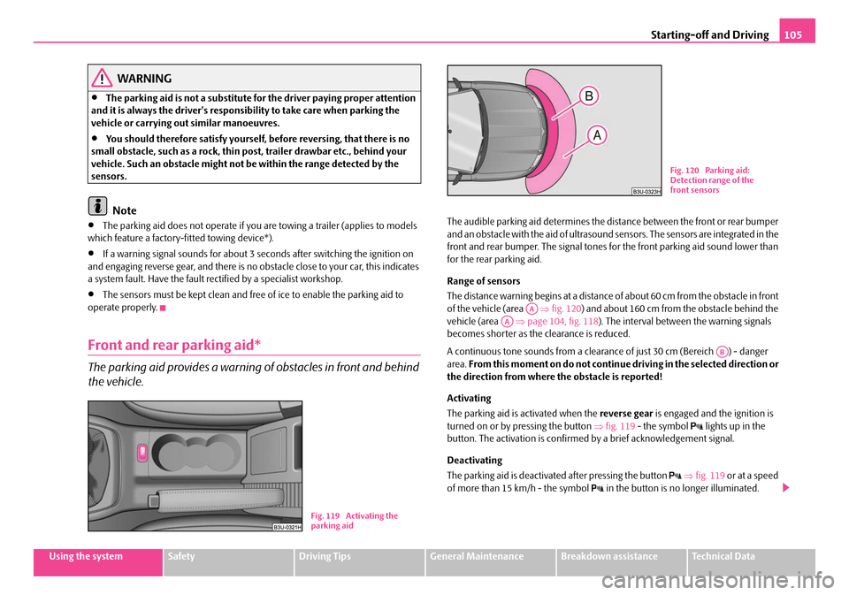
The distance warning begins at a distance of about 60 cm from the obstacle in front
of the vehicle (area ⇒fig. 120 ) and about 160 cm from the obstacle behind the
vehicle (area ⇒page 104, fig. 118 ). The interval between the warning signals
becomes shorter as the clearance is reduced.
A continuous tone sounds from a cleara nce of just 30 cm (Bereich ) - danger
area. From this moment on do not continue driving in the selected direction or
the direction from where the obstacle is reported!
Activating
The parking aid is activated when the reverse gear is engaged and the ignition is
turned on or by pressing the button ⇒fig. 119 - the symbol
lights up in the
button. The activation is confirmed by a brief acknowledgement signal.
Deactivating
The parking aid is deactivated after pressing the button
⇒ fig. 119 or at a speed
of more than 15 km/h - the symbol in the button is no longer illuminated.
B1Z-0042HB1Z-0042HFig. 119 Activating the
parking aid
B1Z-0042HB1Z-0042H
Fig. 120 Parking aid:
Detection range of the
front sensors
AAAA
AB
NKO B5 20.book Page 105 Friday, March 2, 2007 1:46 PM
Page 107 of 259
Starting-off and Driving
106
WARNING
•The parking aid is not a substitute fo r the driver paying proper attention
and it is always the driver's responsibility to take care when reversing the
vehicle or carrying out similar manoeuvres.
•You should therefore satisfy yourself, before reversing, that there is no
small obstacle, such as a rock, thin post, trailer drawbar etc., in front or
behind your vehicle. Such an obstacle might not be within the range
detected by the sensors.
Note
•Only the front parking aid operates if yo u are towing a trailer (applies only to
models which feature a factor y-fitted towing device*).
•If a warning signal sounds for about 3 seconds after activating the system and
there is no obstacle close to your car, th is indicates a system fault. The fault is
confirmed additionally when the symbol
flashes in the button ⇒page 105,
fig. 119 . Have the fault rectified by a specialist workshop.
•The sensors must be kept clean and free of ice to enable the parking aid to
operate properly.
Cruise control system (CCS)*
Introduction
The cruise control system (CCS) maintains a constant speed, more than 30 km/h (20
mph), once it has been set, without you having to depress th e accelerator pedal.
This is only possible within the range which is permitted by the power output and
braking power of the engine. The cruise control system makes it possible - particu-
larly on long journeys - for you to rest your “accelerator foot”.
WARNING
•The cruise control system must not, for safety reasons, be used in dense
traffic or on unfavourable road surfaces (such as icy roads, slippery roads or
loose chippings) - risk of accident!
•In order to prevent unintentional use of the cruise control system, always
switch off the system after use.
Note
•Models fitted with a manual gearbox: Always depress the clutch pedal if you
switch on the cruise control system when the gearbox is in Neutral. Otherwise the
engine can rev up unintentionally.
•The cruise control system is not able to maintain a constant speed when driving
on steep downhill sections. The weight of the vehicle increases the speed at which
it travels. One should shift down in good time to a lower gear or slow the vehicle
down by applying the foot brake.
•It is not possible on vehicl es fitted with an automatic gearbox to switch on the
cruise control system if the selector lever is in the position P, N , R or 2.
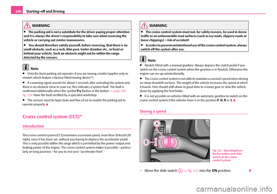
Storing a speed
– Move the slide switch ⇒fig. 121 into the ON position.
B1Z-0042HB1Z-0042H
Fig. 121 Operating lever:
Rocker button and slide
switch on the cruise
control system
AA
NKO B5 20.book Page 106 Friday, March 2, 2007 1:46 PM
Page 170 of 259
Towing a trailer169
Using the systemSafetyDriving TipsGeneral MaintenanceBreakdown assistanceTechnical Data
Towing a trailer
Towing a trailer
Technical requirements
The towing device must satisfy certain technical requirements.
Your vehicle is designed primarily for tran sporting persons and luggage. It can,
however, also be used for towing a trailer - provided certain technical equipment is
fitted.
If your vehicle has alre ady been supplied with a factory-fitted towing device then
everything that is necessary for towing a tr ailer in technical terms, and in terms of
the law, has already been taken into account.
Your vehicle is fitted with a 13-pin powe r socket for the electrical connection
between the vehicle and trailer. If the trailer which you wish to tow has a 7-pin
connector , you can use a suitable adapter
4) from Škoda original accessories.
This work must be carried out in accordan ce with the manufacturer's specifications
if a towing device is retrofitted.
Škoda Service Partners are familiar with details relating to retrofitting a towing
device and for any necessary modi fications to the cooling system.
WARNING
We recommend that you have the towing device from Škoda original acces-
sories installed by a Škoda Service Partner. H e is fa m il ia r wit h al l the re le v a nt
details relating to retrofitting such equipment. There is a risk of an accident
if the towing device is not properly fitted!
General Maintenance
There are a number of points to pay attention to when towing a
trailer.
Trailer load
The permissible trailer load must on no account be exceeded.
You can negotiate appropriately steeper incl ines and descents if you do not make
full use of the permissible trailer load.
The trailer loads specified only apply for altitudes up to 1 000 metres above mean
sea level. The fact that the engine power ou tput drops with increasing height due to
a lowering of air pressure and thus the abil ity to climb, means that the towed weight
must be reduced by 10% for every further increase of 1 000 metres in height above
sea level. The towed weight is the weight of the (laden) vehicle and the (laden)
trailer together. One should take this into account before driving up to higher alti-
tudes.
The trailer and drawbar load information on the type plate of the towing
device are merely test data for the towi ng device The data relating to your
vehicle, which is often less than this test data, can be found in your vehicle
registration documents.
Distribution of the load
Distribute the load in the trailer in such a way that any heavy items are located as
close as possible to the axle. Secure the items to prevent them slipping.
Tyre pressure
Select the tyre inflation pressure on yo ur vehicle for that of “fully laden”,
⇒ page 200. The inflation pressure of the tyres fitted to the trailer adjust in accord-
ance with the manufacturer's recommendation.
Exterior mirrors
You have to have additional exterior mirr ors fitted if you are not able to see the
traffic behind the trailer with the standard rear-view mirrors. Both exterior mirrors
4)In some countries the adapter is supplied with the towing device.
NKO B5 20.book Page 169 Friday, March 2, 2007 1:46 PM
Page 210 of 259
Breakdown assistance209
Using the systemSafetyDriving TipsGeneral MaintenanceBreakdown assistanceTechnical Data
•The factory-supplied lifting jack is only intended for your model of
vehicle. On no account attempt to lift a heavier vehicle or other loads - risk
of injury!
•Ensure that the vehicle tool kit is safely attached in the luggage
compartment.
Spare wheel
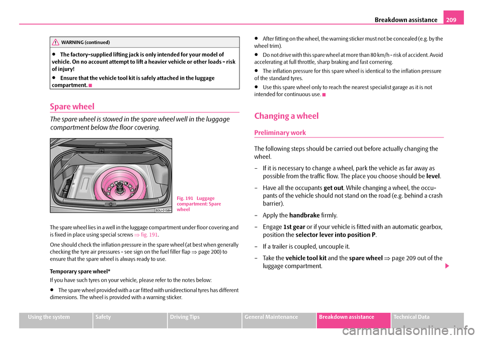
The spare wheel is stowed in the spare wheel well in the luggage
compartment below the floor covering.
The spare wheel lies in a well in the luggage compartment under floor covering and
is fixed in place using special screws ⇒fig. 191 .
One should check the inflation pressure in the spare wheel (at best when generally
checking the tyre air pressures - see sign on the fuel filler flap ⇒page 200) to
ensure that the spare wheel is always ready to use.
Temporary spare wheel*
If you have such tyres on your vehicle, please refer to the notes below:
•The spare wheel provided with a car fitted with unidirectional tyres has different
dimensions. The wheel is provided with a warning sticker.
•After fitting on the wheel, the warning st icker must not be concealed (e.g. by the
wheel trim).
•D o n o t d r i v e w i t h th i s s p a re w h e e l a t m o re th a n 8 0 k m / h - ri s k o f a c c i d e n t. Av o i d
accelerating at full throttle, sharp braking and fast cornering.
•The inflation pressure for this spare wheel is identical to the inflation pressure
of the standard tyres.
•Use this spare wheel only to reach the nearest specialist garage as it is not
intended for continuous use.
Changing a wheel
Preliminary work
The following steps should be carried out before actually changing the
wheel.
– If it is necessary to change a wheel, park the vehicle as far away as possible from the traffic flow. The place you choose should be level.
– Have all the occupants get out. While changing a wheel, the occu-
pants of the vehicle should not stan d on the road (e.g. behind a crash
barrier).
– Apply the handbrake firmly.
–Engage 1st gear or if your vehicle is fitted with an automatic gearbox,
position the selector lever into position P.
– If a trailer is coupled, uncouple it.
– Take the vehicle tool kit and the spare wheel ⇒ page 209 out of the
luggage compartment.
WARNING (continued)
B1Z-0042HB1Z-0042H
Fig. 191 Luggage
compartment: Spare
wheel
NKO B5 20.book Page 209 Friday, March 2, 2007 1:46 PM
Page 218 of 259
Breakdown assistance217
Using the systemSafetyDriving TipsGeneral MaintenanceBreakdown assistanceTechnical Data
Tow-starting and towing vehicle
General
Please pay attention to the following in structions if you are going to use a
tow rope:
Driver of the towing vehicle
– Do not drive off until the tow rope is taught.
– Release the clutch particularly gent ly when starting off or depress the
accelerator particularly gently if yo ur vehicle is fitted with an auto-
matic gearbox.
Driver of the towed vehicle
– Switch the ignition on so that the steering wheel is not blocked and you can also operate the turn signal lights, the headlight flasher, the
windscreen wipers and windscreen washer system.
– Take the vehicle out of gear or move the selector lever into position N
if your vehicle is fitted with an automatic gearbox.
– Note that the brake servo unit and power steering only operate if the engine is running. You will require si gnificantly greater physical force
to depress the brake pedal and to steer the vehicle if the engine is not
running.
– Ensure that the tow rope is always kept taught.
Tow rope or tow bar
A tow bar is safest way of towing a vehicle and also minimizes any shocks. You can
use a tow rope only if a suitable to w bar is not available.
The tow rope must be elastic to protect the vehicle. Thus one should only use
plastic fibre rope or a rope made out of a similarly elastic material. Attach the tow rope or the tow bar only to the
towing eyes provided for this
purpose ⇒page 218, “Front towing eye” and ⇒page 218, “Rear towing eye”.
Driving style
Towing another vehicle requires a certain amount of practice. Both drivers should
be familiar with the partic ular points about towing a vehicle. Unskilled drivers
should not attempt to tow in another vehicle or to be towed in.
One should be constantly vigi lant not to allow impermissibly high towing forces or
jerky loadings. There is always a risk of excessive stresses and damage resulting at
the points to which you attach the tow rope or tow bar when you attempt to tow a
vehicle which is not stan ding on a paved road.
Caution
If the gearbox of your vehicle no longer contains any oil because of a defect, your
vehicle must only be towed in with the driven wheels raised clear of the ground, or
on a special vehicle transporter or trailer.
Note
•Please comply with any legal requiremen ts particularly regarding the switched
on signal systems, when towing in or tow-starting another vehicle.
•The tow rope must not be twisted as it may in certain circumstances result in the
front towing eye being unscrewed out of your vehicle.
NKO B5 20.book Page 217 Friday, March 2, 2007 1:46 PM
Page 219 of 259
Breakdown assistance
218
Front towing eye
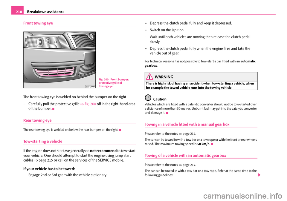
The front towing eye is welded on behind the bumper on the right.
– Carefully pull the protective grille ⇒fig. 200 off in the right-hand area
of the bumper.
Rear towing eye
The rear towing eye is welded on below the rear bumper on the right.
Tow-starting a vehicle
If the engine does not start, we generally do not recommend to tow-start
your vehicle. One should attempt to start the engine using jump start
cables ⇒page 215 or call on the servic es of the SERVICE mobile.
If your vehicle has to be towed:
– Engage 2nd or 3rd gear wi th the vehicle stationary. – Depress the clutch pedal fully and keep it depressed.
– Switch on the ignition.
– Wait until both vehicles are movi
ng then release the clutch pedal
slowly.
– Depress the clutch pedal fully when the engine fires and take the vehicle out of gear.
For technical reasons it is not possib le to tow-start a car fitted with an automatic
gearbox .
WARNING
There is high risk of having an accident when tow-starting a vehicle, when
for example the towed vehicle runs into the towing vehicle.
Caution
Vehicles which are fitted with a catalytic converter should not be tow-started over
a d i s t a n c e o f m o re t h a n 5 0 m e t re s . U n b u r n t fuel may get into the catalytic converter
and damage it.
Towing in a vehicle fitted with a manual gearbox
Please refer to the notes ⇒ page 217.
The car can be towed in with a tow bar or a tow rope or with the front or rear wheels
raised. The maximum towing speed is 50 km/h.
Towing of a vehicle with an automatic gearbox
Please refer to the notes ⇒ page 217.
The car can be towed in with a tow bar or a tow rope. Refer at the same time to the
following guidelines:
Fig. 200 Front bumper:
protective grille of
towing eye
NKO B5 20.book Page 218 Friday, March 2, 2007 1:46 PM