sensor SKODA SUPERB 2008 2.G / (B6/3T) Owner's Guide
[x] Cancel search | Manufacturer: SKODA, Model Year: 2008, Model line: SUPERB, Model: SKODA SUPERB 2008 2.G / (B6/3T)Pages: 272, PDF Size: 18.25 MB
Page 184 of 272

Intelligent Technology185
Using the systemSafetyDriving TipsGeneral MaintenanceBreakdown assistanceTechnical Data
Tyre inflation pressure-control system*
The tyre inflation pressure-control system compares with the aid of the ABS sensors
the speed and also the rolling circumference of the individual wheels. If the rolling
circumference of a wheel is changed, the warning light
lights up in the dash
panel insert ⇒page 32. The rolling circumference of the tyre can change if:
•the tyre inflation pressure is too low,
•the structure of the tyre is damaged,
•the vehicle is loaded on one side,
•the wheels of an axle are loaded heavily (e.g. when towing a trailer or when
driving uphill or downhill),
•snow chains are mounted,
•the temporary spare wheel is mounted,
•one wheel per axle was changed.
Basic setting of tyre inflation pressure-control system
After changing the tyre inflation pressures or after changing one or several wheels,
a basic setting of the system must be carried out as follows.
•Inflate all tyres to the specified inflation pressure ⇒page 222.
•Switch on the ignition.
•Press button ⇒ fig. 177 for more than 2 seconds. While pressing the
button, the warning light lights up. At the same time the memory of the system is erased and the new calibration is star
ted, which is confirmed with an audible
signal and then the warning light
goes out.
•If the warning light does not go out after the basic setting, there is a fault in
the system. Have the vehicle inspected by your nearest specialist garage.
Warning light
lights up
If the tyre inflation pressure of at least on e wheel is insufficiently inflated in compar-
ison to the stored basic value, the warning light
⇒ lights up.
Warning light
flashes
If the warning light flashes, there is a system fault. Have the vehicle inspected by
your nearest specialist garage.
WARNING
•When the warning light lights up, immediately reduce the speed and
avoid sudden steering and brake mano euvres. Please stop the vehicle
without delay at the nearest possible stop and inspect the tyres and their
inflation pressures.
•The driver is responsible for the correc t tyre inflation pressures. For this
reason, the tyre inflation pressures must be checked regularly.
•Under certain circumstances (e.g. sporty style of driving, wintry or
unpaved roads) the warning light can be delayed or does not light up at
all.
•The tyre inflation pressure-control system does not take away the
responsability from the driver for the correct tyre inflation pressure.
Note
The tyre inflation pressure-control system:
•does not replace the regular tyre inflatio n pressure control, because the system
cannot detect an even pressure loss,
•cannot warn in case of very rapid tyre inflation pressure loss, e.g. in case of
sudden tyre damage. In this case carefully bring the vehicle to a standstill without
sudden steering movements and without sharp braking.
Fig. 177 Button for setting
the tyre inflation pressure
control value
NKO B6 20.book Page 185 Wednesday, March 26, 2008 3:15 PM
Page 244 of 272

Fuses and light bulbs245
Using the systemSafetyDriving TipsGeneral MaintenanceBreakdown assistanceTechnical Data
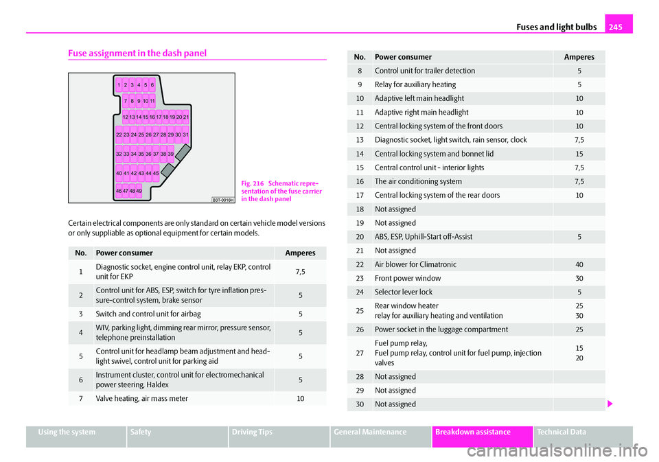
Fuse assignment in the dash panel
Certain electrical components are only standard on certain vehicle model versions
or only suppliable as optional equipment for certain models.
No.Power consumerAmperes
1Diagnostic socket, engine cont rol unit, relay EKP, control
unit for EKP7,5
2Control unit for ABS, ESP, swit ch for tyre inflation pres-
sure-control system, brake sensor5
3Switch and control unit for airbag5
4WIV, parking light, dimming rear mirror, pressure sensor,
telephone preinstallation5
5Control unit for headlamp beam adjustment and head-
light swivel, control unit for parking aid5
6Instrument cluster, control unit for electromechanical
power steering, Haldex5
7Valve heating, air mass meter10
Fig. 216 Schematic repre-
sentation of the fuse carrier
in the dash panel
8Control unit for trailer detection5
9Relay for auxiliary heating5
10Adaptive left main headlight10
11Adaptive right main headlight10
12Central locking system of the front doors10
13Diagnostic socket, light switch, rain sensor, clock7,5
14Central locking system and bonnet lid15
15Central control unit - interior lights7,5
16The air conditioning system7,5
17Central locking system of the rear doors10
18Not assigned
19Not assigned
20ABS, ESP, Uphill-Start off-Assist5
21Not assigned
22Air blower for Climatronic40
23Front power window30
24Selector lever lock5
25Rear window heater
relay for auxiliary heating and ventilation25
30
26Power socket in the luggage compartment25
27Fuel pump relay,
Fuel pump relay, control unit for fuel pump, injection
valves15
20
28Not assigned
29Not assigned
30Not assigned
No.Power consumerAmperes
NKO B6 20.book Page 245 Wednesday, March 26, 2008 3:15 PM