sensor SKODA SUPERB 2009 2.G / (B6/3T) Owner's Guide
[x] Cancel search | Manufacturer: SKODA, Model Year: 2009, Model line: SUPERB, Model: SKODA SUPERB 2009 2.G / (B6/3T)Pages: 294, PDF Size: 21.33 MB
Page 127 of 294
Starting-off and Driving
126
Switch on display of the park assist in the information display* – Press the button
⇒
fig. 141
.
– Drive past the parking row up to maximum 30 km/h and with a
distance of 0.5 m to 1.5 m
⇒
page 125, fig. 142
.
Operate the turn signal for the driver's side
if you wish to park on this side of the
road. In the information display* the search area for the parking place is indicated on the driver's side. If the button is pressed above a speed of 30 km/h, the display appears in the display of the instrument cluster as soon as you drive slower than 30 km/h.
Note
•
If the park assist is switched on, a yello
w warning light lights up in the button.
•
The search for suitable parking places is automatic after switching on the igni-
tion at speeds of more than 30 km/h. Searching for a parking place is performed at the same time on the driver and front passenger side.•
If the sensors find a suitable parking place, they store its parameters until
another suitable parking place has been found or until a distance of 10 m had been driven after finding the parking place. This is
why it is possible to switch on the park
assist after driving past the parking space,
on the information display* appears the
information if this parking space is suitable for parking.
Parking with the help of the pa
rk assist and concluding the
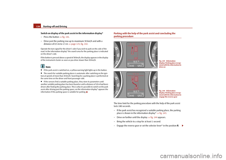
parking procedureThe time limit for the parking procedure with the help of the park assist lasts 180 seconds. – If the park assist has recognized a suitable parking place, the parking
place is shown in the information display*
⇒
fig. 143
.
– Drive on further until the display
⇒
fig. 144
appears.
– Bring the vehicle to a stop for at least 1 second. – Engage the reverse gear or set the selector lever* in the position
R.
Fig. 143 Information display: Parking place recog-nized with the information to drive onFig. 144 Information display: Parking place recog-nized with the information to engage the reverse gear
s2dk.1.book Page 126 Wednesday, April 8, 2009 12:23 PM
Page 181 of 294
Airbag system
180
Important safety information on the side airbag Correct use of the airbag system considerably reduces the risk of injury!
WARNING
•
It is essential to always switch off
⇒page 182, “Deactivating an airbag”
the front passenger airbag when attaching a child safety seat on the front passenger seat where the child is seated
with its back facing in direction of
travel (in some countries also when the ch
ild is facing the direction of travel).
If this is not done, there is a risk of the child suffering severe or even fatal injuries if the front passenger airbag
is deployed. In certain countries
national legal provisions also requir
e that the side or head passenger
airbags be deactivated. When transporting a child on the front passenger seat, please comply with the appropri
ate national regula
tions regarding the
use of child safety seats.•
Your head should never be positioned
in the deployment area of the side
airbag. You might suffer severe injuries in the event of an accident. This applies in particular to children who are transported without using a suit- able child safety seat
⇒page 187, “Child safety and side airbag*”.
•
If children adopt an incorrect seated position when travelling, they may
be exposed to an increased risk of injury
in the event of an accident. This can
result in serious injuries
⇒page 185, “What you should know about trans-
porting children!”.•
There must not be any further persons,
animals as well as objects posi-
tioned between the occupants and the de
ployment area of the airbag. There
must also be no accessories such as cup holders, attached to the doors to enable the side airbags to activate properly.•
The airbag control unit operates to
gether with the pressure sensors,
which are attached in the front doors. For this reason no adjustments must be carried out at the doors as well as at the door panels (for example addi- tional installation of loudspeakers).
Resulting damages can have a negative
affect on the operation of the airbag system. All work on the front doors and their panels must only be carried out by a specialist garage.
•
In the event of a side collision, the side airbags will not function properly,
if the sensors cannot measure the increasing air pressure inside the doors, because the air can escape through lar
ge, non-sealed openings in the door
panel.
− Never drive with removed inner door panels. − Never drive, if parts of the inner
door panel have been removed and
the remaining openings have not been properly sealed. − Never drive, if the loudspeakers in the doors have been removed, only if the loudspeaker openings have been properly sealed. − Always make sure that the openings
are covered or filled, if additional
loudspeakers or other equipment part
s are installed in the inner door
panels. − Always work with an authorised Škoda dealer or have it carried out by a competent specia
list workshop.
•
Only hang light items of clothing on the clothes hooks to the vehicle.
Never leave any heavy or sh
arp-edged objects in the pockets of the items of
clothing.•
Ensure that there are no excessive fo
rces, such as violent knocks, kicks
etc., impact on the backrests of th
e seats otherwise the system may be
damaged. The side airbags would not be deployed in such a case!•
Any seat or protective covers which you fit to the driver or front
passenger seats must only be of the type expressly authorised by Škoda Auto. In view of the fact that the airbag inflates out of the backrest of the seat, use of non-approved seat or protective covers would considerably impair the protective function of the side airbag.•
Any damage to the original seat covers in the area of the side airbag
module must be repaired without
delay by your specialist garage.
•
The airbag modules in the front se
ats must not display any damage,
cracks or deep scratches. It is not permissible to use force in order to open the modules.
WARNING (continued)
s2dk.1.book Page 180 Wednesday, April 8, 2009 12:23 PM
Page 183 of 294
Airbag system
182
offers additional protection in the case of
an offset impact by covering the front
door pillar. In certain accident situations, the front,
side and head airbag are simultaneously
deployed. The airbags inflate in fractions of a second
and at a high speed in order to be able
to offer that additional protection in th
e event of an accident. A grey white, non
harmful gas is released when airbag is inflated. This is perfectly normal and is not an indication of a fire in the vehicle.Important safety information on the head airbag Correct use of the airbag system considerably reduces the risk of injury!
WARNING
•
It is essential to always switch off
⇒page 182, “Deactivating an airbag”
the front passenger airbag when attaching a child safety seat on the front passenger seat where the child is seated
with its back facing in direction of
travel (in some countries also when the ch
ild is facing the direction of travel).
If this is not done, there is a risk of the child suffering severe or even fatal injuries if the front passenger airbag
is deployed. In certain countries
national legal provisions also requir
e that the side or head passenger
airbags be deactivated. When transporting a child on the front passenger seat, please comply with the appropri
ate national regula
tions regarding the
use of child safety seats.•
There must not be any objects in the deployment area of the head
airbags which might prevent the airbags from inflating properly.•
Only hang light items of clothing on the clothes hooks to the vehicle.
Never leave any heavy or sharp-edged ob
jects in the pockets of the items of
clothing. In addition, it is not permitted to use clothes hangers for hanging up items of clothing.•
The airbag control unit operates to
gether with the sensors, which are
attached in the front doors. For this reason no adjustments must be carried out at the doors as well as at the door panels (for example additional instal-
lation of loudspeakers). Resulting dama
ges can have a negative affect on the
operation of the airbag system. All work on the front doors and their panels must only be carried out by a specialist garage.•
There must not be any other persons
(e.g. children) or animals between
the car occupant and the deployment area of the head airbag. In addition, none of the occupants should lean their head out of the window when driving, or extend their arms and hands out of the window.•
The sun visors must not be swivelled to the side windows into the
deployment area of the head airbags if any objects, such as ball-point pens etc. are attached to them. This might resu
lt in injuries to
the occupants if the
head airbag is deployed.•
Installing impermissible accessories in the area of the head airbags may
considerably impair the protection offere
d by the head airbag in the event of
it being deployed. When the deployed head airbag is inflated, parts of the accessories fitted may in certain circum
stances be thrown into the interior
of the car and cause injuries to the occupants
⇒page 241, “Accessories,
changes and replacement of parts”.•
Any work on the head airbag system including installing and removing
system components because of other repair work (e.g. removing headliner) must only be carried out by a specialist garage.Deactivating an airbagDeactivating airbags If any airbags have been deactivated, switch them on again as soon as possible so that they are able to
again provide their proper protec-
tion.There is the technical means installed within
your vehicle to switch off the front,
side or head* airbag (take out of commission). This is why you should have the deacti
vation of the airbags carried out by a
specialist garage.
WARNING (continued)
s2dk.1.book Page 182 Wednesday, April 8, 2009 12:23 PM
Page 194 of 294
Intelligent Technology
193
Using the system
Safety
Driving Tips
General Maintenance
Breakdown assistance
Technical Data
Driving TipsIntelligent TechnologyElectronic stability programme (ESP)*GeneralGeneral The ESP aids you maintain control of your vehicle in situations in borderline driving situations such as when negotiating a curve too fast. The risk of skidding is reduced and your car thus offers greater driving stability depending on the conditions of the road surface. This occurs at all speeds. The following systems are integrated into the electronic stability programme:•
Electronic Differential Lock (EDL),
•
Traction control system (TCS),
•
Active driver-steering recommendation (DSR),
•
Antilock brake system (ABS),
•
Brake Assist,
•
Uphill-Start off-Assist.
Operating principle The ESP switches on automatically when the engine is started and then conducts a self-test. The ESP control unit processes data from the individual systems. It also processes additional measurement data which are supplied by highly sensitive sensors: the rotational velocity of the vehi
cle about its vertical axis, the lateral accel-
eration of the vehicle, the brakin
g pressure and the steering angle.
The direction which the driver wishes to ta
ke is determined based on the steering
angle and the speed of the vehicle and is constantly compared with the actual behaviour of the vehicle. If differences exis
t, such as the car beginning to skid, the
ESP will automatically brake the appropriate wheel. The car is stabilised again by the forces which take effect when the wheel is braked. Intervention into the brake system takes place primarily on the outer front wheel of a vehicle which tends to oversteer (tendency for the rear of the vehicle to break away) while occurs this is on the inner re
ar wheel of a vehicle which tends to under-
steer (tendency to shift out of the curve). This braking control cycle is accompanied by noises. The ESP operates in combination with the ABS
⇒page 197. If there is a fault in the
ABS system, the ESP also does not operate. The ESP warning light lights up in the instru
ment cluster when there is a fault on the
ESP
⇒page 39.
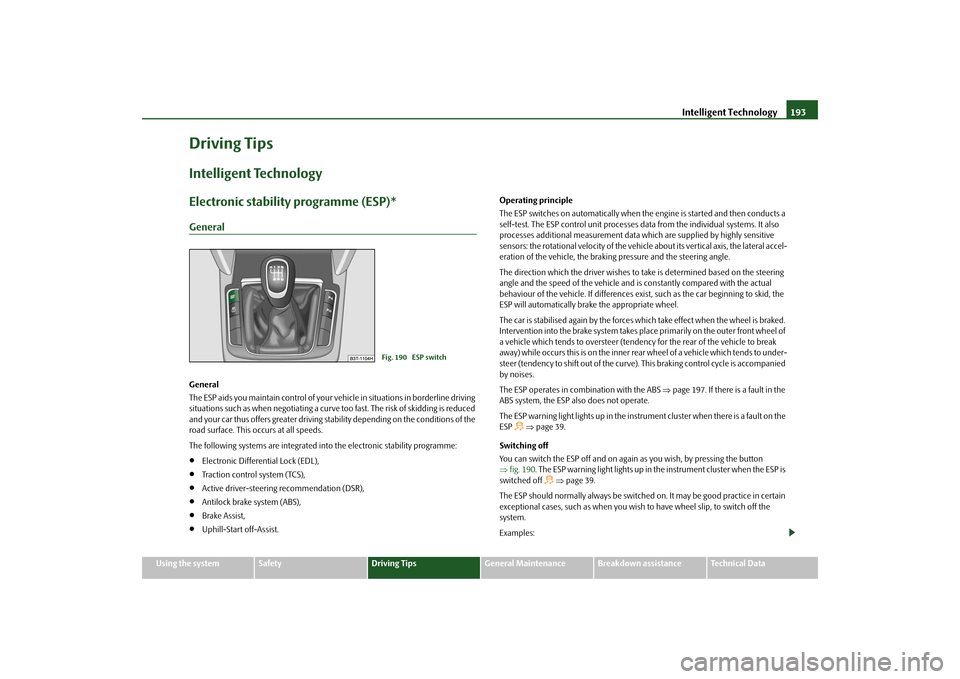
Switching off You can switch the ESP off and on again
as you wish, by pressing the button
⇒ fig. 190
. The ESP warning light lights up in th
e instrument cluster when the ESP is
switched off
⇒page 39.
The ESP should normally always be switched
on. It may be good practice in certain
exceptional cases, such as when you wish
to have wheel slip, to switch off the
system. Examples:
Fig. 190 ESP switch
s2dk.1.book Page 193 Wednesday, April 8, 2009 12:23 PM
Page 195 of 294
Intelligent Technology
194
•
when driving with snow chains
•
when driving in deep snow or on a loose surface
•
when it is necessary to rock a ca
r free when it has become stuck.
then you should switch on the ESP again.
WARNING
It is also not possible for the ESP to overcome the physical limits of the vehicle. Even if a vehicle fitted with ESP you should still always adapt your style of driving to the condition of the
road surface and the traffic situation.
This particularly applies when driving on slippery and wet roads. The increased safety offered must not tempt you to take greater risks than other- wise - risk of an accident!
Note
•
All four wheels must be fitted with the same tyres in order to achieve problem-
free operation of the ESP. Differing rolling
circumferences of the tyres can lead to an
undesirable reduction in the engine output.•
Changes to vehicle (e.g. on engine, on the brakes, on chassis or other assign-
ment of tyres and wheels) can influence the function of the ESP
⇒page 241,
“Accessories, changes and replacement of parts”.Electronic Differential Lock (EDL)* The electronic differential lock pr
events an individual wheel from
slipping.Models fitted with ESP are equipped with electronic differential lock (EDL). General The EDL makes it much easier, and sometimes at all possible, to start off, accelerate and climb a steep hill when the conditio
ns of the road surface are unfavourable.
Operating principle The EDL is activated automatically, that is
without any action on the part of the
driver. It monitors the speeds of the driven wheels with the aid of the ABS sensors. Should only
one
drive wheel begin spinning on a slippery surface there will be an
appreciable difference in the speed of the driven wheels. The EDL function brakes the slipping wheel and the differential transmits a greater driving force to the other driven wheel. This control proces
s is also accompanied by noises.
Overheating of the brakes The EDL switches off
automatically if unusually severe
stresses exist in order to
avoid excessive heat generation in the
disc brake on the wheel which is being
braked. The vehicle can continue to be driv
en and has the same characteristics as a
vehicle not fitted with EDL. The EDL switches on again
automatically as soon as the brake has cooled down.
WARNING
•
Depress the accelerator carefully when accelerating on uniformly slip-
pery road surfaces, such as ice and sn
ow. The driven wheels might still spin
despite the EDL and affect the stability
of the vehicle - risk of an accident!
•
You should always adapt your style of driving to the condition of road
surface and to the traffic situation even
when your vehicle is fitted with EDL.
The increased safety offered must not tempt you to take greater risks than otherwise - risk of an accident!
Note
•
If the ABS or ESP warning light comes on,
this may also indicate a fault in the
EDL. Please have the car inspected as s
oon as possible by a specialist garage.
•
Changes to vehicle (e.g. on engine, on
the brakes, on chassis or other assign-
ment of tyres and wheels) can in
fluence the function of the EDL
⇒page 241,
“Accessories, changes and
replacement of parts”.
s2dk.1.book Page 194 Wednesday, April 8, 2009 12:23 PM
Page 196 of 294
Intelligent Technology
195
Using the system
Safety
Driving Tips
General Maintenance
Breakdown assistance
Technical Data
Traction control system (TCS) The traction control system prevents
the driven wheels from spinning
when accelerating.General The TCS makes it much easier, and sometimes at all possible, to start off, accelerate and climb a steep hill when the conditio
ns of the road surface are unfavourable.
Operating principle The TCS switches on automatically when th
e engine is started and then conducts a
self-test. The system monitors the speeds of the driven wheels with the aid of the ABS sensors. If the wheels are spinning, the force transmitted to the road surface is automatically adapted by redu
cing the engine speed. Th
is occurs at all speeds.
The TCS operates in combination with the ABS
⇒page 197. The TCS will not func-
tion if a fault exists in the ABS system. The TCS warning light lights up in the instrument cluster when there is a fault on the TCS
⇒page 38.
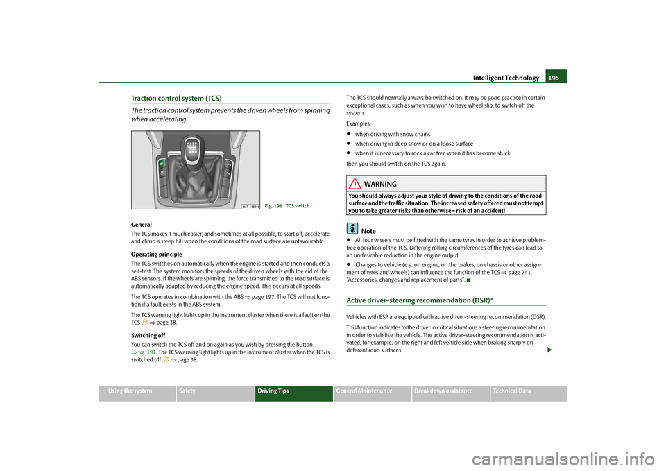
Switching off You can switch the TCS off and on again
as you wish by pressing the button
⇒ fig. 191
. The TCS warning light lights up in the instrument cluster when the TCS is
switched off
⇒page 38.
The TCS should normally always be switched on. It may be good practice in certain exceptional cases, such as when you wish
to have wheel slip, to switch off the
system. Examples:•
when driving with snow chains
•
when driving in deep snow or on a loose surface
•
when it is necessary to rock a car free when it has become stuck.
then you should switch on the TCS again.
WARNING
You should always adjust your style of driving to the conditions of the road surface and the traffic situation. The increased safety offered must not tempt you to take greater risks than otherwise - risk of an accident!
Note
•
All four wheels must be fitted with the same tyres in order to achieve problem-
free operation of the TCS. Differing rolling circumferences of the tyres can lead to an undesirable reduction in the engine output.•
Changes to vehicle (e.g. on engine, on the brakes, on chassis or other assign-
ment of tyres and wheels) can in
fluence the function of the TCS
⇒page 241,
“Accessories, changes and replacement of parts”.Active driver-steering recommendation (DSR)*Vehicles with ESP are equi
pped with active driver-steering recommendation (DSR).
This function indicates to the driver in critical situations a steering recommendation in order to stabilise the vehicle. The active driver-steering recommendation is acti- vated, for example, on the right and left
vehicle side when
braking sharply on
different road surfaces.
Fig. 191 TCS switch
s2dk.1.book Page 195 Wednesday, April 8, 2009 12:23 PM
Page 200 of 294
Intelligent Technology
199
Using the system
Safety
Driving Tips
General Maintenance
Breakdown assistance
Technical Data
Tyre inflation pressu
re-control system*
The tyre inflation pressure-control system compares with the aid of the ABS sensors the speed and also the rolling circumference
of the individual wheels. If the rolling
circumference of a wheel is changed, the warning light°
lights up in the instru-
ment cluster
⇒page 39. The rolling circumference of the tyre can change if:
•
the tyre inflation pressure is too low,
•
the structure of the tyre is damaged,
•
the vehicle is loaded on one side,
•
the wheels of an axle are loaded heavily (e.g. when towing a trailer or when
driving uphill or downhill),•
snow chains are mounted,
•
the temporary spare wheel is mounted,
•
one wheel per axle was changed.
Basic setting of tyre inflation pressure-control system After changing the tyre inflation pressures or after changing one or several wheels, a basic setting of the system must be carried out as follows.•
Inflate all tyres to the specified inflation pressure
⇒page 235.
•
Switch on the ignition.
•
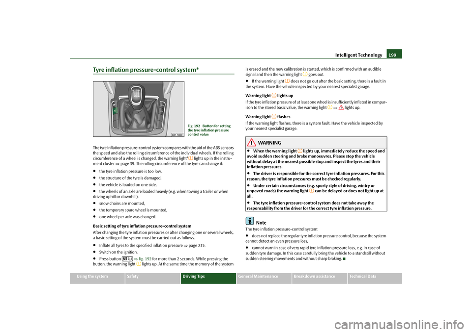
Press button
⇒fig. 192
for more than 2 seconds. While pressing the
button, the warning light
lights up. At the same time the memory of the system
is erased and the new calibration is star
ted, which is confirmed with an audible
signal and then the warning light
goes out.
•
If the warning light
does not go out after the basic setting, there is a fault in
the system. Have the vehicle inspected by your nearest specialist garage. Warning light
lights up
If the tyre inflation pressure of at least on
e wheel is insufficiently inflated in compar-
ison to the stored basic value, the warning light
⇒
lights up.
Warning light
flashes
If the warning light flashes, there is a system fault. Have the vehicle inspected by your nearest specialist garage.
WARNING
•
When the warning light
lights up, immediately reduce the speed and
avoid sudden steering and brake mano
euvres. Please stop the vehicle
without delay at the nearest possible stop and inspect the tyres and their inflation pressures.•
The driver is responsible for the correc
t tyre inflation pressures. For this
reason, the tyre inflation pressures must be checked regularly.•
Under certain circumstances (e.g. sporty style of driving, wintry or
unpaved roads) the warning light
can be delayed or does not light up at
all.•
The tyre inflation pressure-control system does not take away the
responsability from the driver for the correct tyre inflation pressure.
Note
The tyre inflation pressure-control system:•
does not replace the regular tyre inflatio
n pressure control, because the system
cannot detect an even pressure loss,•
cannot warn in case of very rapid tyre inflation pressure loss, e.g. in case of
sudden tyre damage. In this
case carefully bring the vehi
cle to a standstill without
sudden steering movements and without sharp braking.
Fig. 192 Button for setting the tyre inflation pressure control value
s2dk.1.book Page 199 Wednesday, April 8, 2009 12:23 PM
Page 261 of 294
Fuses and light bulbs
260
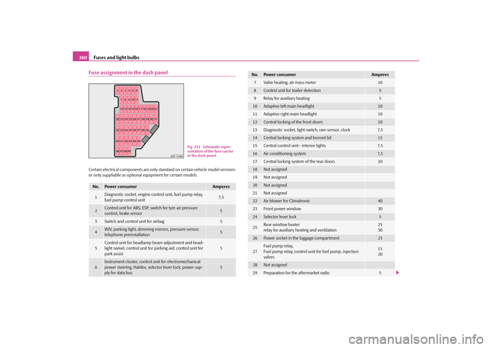
Fuse assignment in the dash panelCertain electrical components are only st
andard on certain vehicle model versions
or only suppliable as optional
equipment for certain models.
No.
Power consumer
Amperes
1
Diagnostic socket, engine control unit, fuel pump relay, fuel pump control unit
7,5
2
Control unit for ABS, ESP, switch for tyre air pressure control, brake sensor
5
3
Switch and control unit for airbag
5
4
WIV, parking light, dimming mirrors, pressure sensor, telephone preinstallation
5
5
Control unit for headlamp beam adjustment and head- light swivel, control unit for parking aid, control unit for park assist
5
6
Instrument cluster, control
unit for electromechanical
power steering, Haldex, selector lever lock, power sup- ply for data bus
5
Fig. 232 Schematic repre- sentation of the fuse carrier in the dash panel
7
Valve heating, air mass meter
10
8
Control unit for trailer detection
5
9
Relay for auxiliary heating
5
10
Adaptive left main headlight
10
11
Adaptive right main headlight
10
12
Central locking of the front doors
10
13
Diagnostic socket, light switch, rain sensor, clock
7,5
14
Central locking system and bonnet lid
15
15
Central control unit - interior lights
7,5
16
Air conditioning system
7,5
17
Central locking system of the rear doors
10
18
Not assigned
19
Not assigned
20
Not assigned
21
Not assigned
22
Air blower for Climatronic
40
23
Front power window
30
24
Selector lever lock
5
25
Rear wind
ow heater
relay for auxiliary heating and ventilation
2530
26
Power socket in the luggage compartment
25
27
Fuel pump relay, Fuel pump relay, control unit for fuel pump, injection valves
1520
28
Not assigned
29
Preparation for the aftermarket radio
5
No.
Power consumer
Amperes
s2dk.1.book Page 260 Wednesday, April 8, 2009 12:23 PM