parking brake SKODA SUPERB 2009 2.G / (B6/3T) Owner's Manual
[x] Cancel search | Manufacturer: SKODA, Model Year: 2009, Model line: SUPERB, Model: SKODA SUPERB 2009 2.G / (B6/3T)Pages: 294, PDF Size: 21.33 MB
Page 42 of 294
Instruments and Indicator/Warning Lights
41
Using the system
Safety
Driving Tips
General Maintenance
Breakdown assistance
Technical Data
The following text will be displayed in the information display*:
Check brake pads!
Boot lid
The warning light
comes on when the ignition is switched on if the luggage
compartment door is open. If the boot li
d opens while driving, the warning light
lights up
and as a warning an audible signal sounds.
The warning light comes on even when the
ignition is switched off. The warning
light lights up for a maximum of 5 minutes. On vehicles with information display* th
is warning light is replaced by a vehicle
symbol
⇒page 28, fig. 29
.
Open door
The warning light
comes on if one or several door
s are opened or if the boot lid
is opened. If one of the doors opens while driving, the warning light lights
up
and an audible signal sounds. The warning light comes on even when the
ignition is switched off. The warning
light lights up for a maximum of 5 minutes. On vehicles with information display* th
is warning light is replaced by a vehicle
symbol
⇒page 28, fig. 29
.
Liquid in reservoir for windscreen washer system
The warning light
comes on when the ignition is switched on if there is insuffi-
cient fluid in the windshield wash
er system. Top up with liquid
⇒page 234.
The following text will be displayed in the information display*:
Add wash fluid!
Brake system
The warning light
flashes or comes on if the brake fluid level is too low, if there
is a fault in the ABS or if
the handbrake is applied.
If the warning light
flashes and an audible signal sounds three times (handbrake
is not applied),
stop
and check the brake fluid level
⇒
.
The following text will be displayed in the information display*:
Brake fluid Owner's manual
If there is a fault in the ABS which also influences the function of the brake system (e.g. distribution of brake pressure), the ABS warning light
comes on and at the
same time the brake system warning light starts flashing
. Be aware that not only
the ABS but also another part of th brake system is defective
⇒
.
An audible signal sounds three times as an additional warning signal.One should get used to high pedal forces, long braking distances and long free play of the brake pedal when driving to the next specialist garage. For further information on the brake system
⇒page 196, “Brakes”.
Handbrake applied The warning light
also comes on if the handbrake is applied. An audible warning
is also given if you drive the vehicle for at least 3 seconds at a speed of more than 6 km/h. The following text will be displayed in the information display*:
Release parking brake!
WARNING
•
Pay attention to the following instructions before checking the brake
fluid level and opening the bonnet
⇒page 223, “Working in the engine
compartment”.•
If the brake system warning light
does not go out a few seconds after
switching on the ignition or comes on when driving, stop immediately and check the brake fluid in the reservoir
⇒page 228, “Brake fluid”. If the fluid
s2dk.1.book Page 41 Wednesday, April 8, 2009 12:23 PM
Page 122 of 294
Starting-off and Driving
121
Using the system
Safety
Driving Tips
General Maintenance
Breakdown assistance
Technical Data
Shift into reverse only when the car is stationary. Depress the clutch pedal and hold it fully depressed. Wait a moment before
engaging reverse gear in order to avoid
any shift noises. The reversing lights will come on once reve
rse gear is engaged, provided the igni-
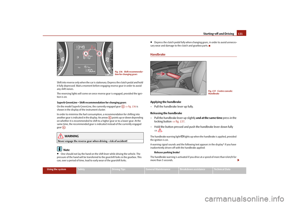
tion is on. Superb GreenLine - Shift recommendation for changing gears On the model Superb GreenLine, the currently engaged gear
⇒fig. 136
is
shown in the display of the instrument cluster. In order to minimise the fuel consumptio
n, a recommendation for shifting into
another gear is indicated in the display. An arrow points up or down depending on whether it is recommended to shift to
a higher gear or to a lower gear. At the
same time, the recommended gear is indicated instead of the currently engaged gear .
WARNING
Never engage the reverse gear when driving - risk of accident!
Note
•
One should not lay the hand on the shift lever while driving the vehicle. The
pressure of the hand will be transferred to the gearshift forks in the gearbox. This can, over a period of time, lead to early wear of the gearshift forks.
•
Depress the clutch pedal fully when changing gears, in order to avoid unneces-
sary wear and damage to the clutch and gearbox parts.HandbrakeApplying the handbrake – Pull the handbrake lever up fully. Releasing the handbrake – Pull the handbrake lever up slightly
and
at the same time
press in the
locking button
⇒
fig. 137
.
– Hold the button pressed and push the handbrake lever down fully
⇒
.
The handbrake warning light
lights up when the handbr
ake is applied, provided
the ignition is on. A warning signal sounds and the following text appears in the display* if you have inadvertently driven off with the handbrake applied:
Release parking brake!
The handbrake warning is activated if you dr
ive at a speed of more than 6 km/h for
more than 3 seconds.
Fig. 136 Shift recommenda- tion for changing gears
AA
AB
AA
Fig. 137 Centre console: Handbrake
s2dk.1.book Page 121 Wednesday, April 8, 2009 12:23 PM
Page 123 of 294
Starting-off and Driving
122
WARNING
•
Please note that the handbrake mu
st be fully released. A handbrake
which is only partially released can re
sult in the rear brakes overheating
which will have a negative effect on th
e operation of the brake system - risk
of accident! In addition this can result in premature wear of the rear brake pads.•
Never leave children unattended in th
e vehicle. The children might, for
example, release the handbrake or take
the vehicle out of gear. The vehicle
might then move off - risk of accident!
Caution
After the car has come to a stop, always firs
t of all apply the handbrake firmly before
then additionally engaging a gear (manual gearbox) or moving the selector lever into position
P (automatic gearbox).
Rear parking aid*The parking aid provides a warning of obstacles behind the vehicle.The audible parking aid determines the distance between the rear bumper and an obstacle located behind the
vehicle with the aid of ultr
asound sensors. The tones
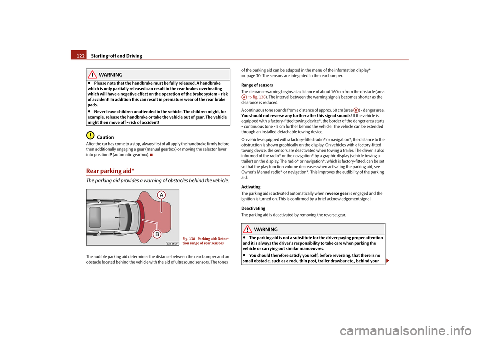
of the parking aid can be adapted in the menu of the information display* ⇒ page 30. The sensors are integrated in the rear bumper. Range of sensors The clearance warning begins at a distance of about 160 cm from the obstacle (area ⇒fig. 138
). The interval between the warning signals becomes shorter as the
clearance is reduced. A continuous tone sounds from a distance
of approx. 30 cm (area ) - danger area.
You should not reverse any further after this signal sounds!
If the vehicle is
equipped with a factory-fitted towing device*, the border of the danger area starts - continuous tone - 5 cm further behind
the vehicle. The vehi
cle can be extended
through an installed deta
chable towing device.
On vehicles equipped with a factory-fitted radio* or navigation*, the distance to the obstruction is shown graphically on the di
splay. On vehicles with a factory-fitted
towing device, the sensors are deactivated wh
en towing a trailer. The driver is also
informed of the radio* or the navigation
* by a graphic display (vehicle towing a
trailer) on the display. The radio* or navi
gation*, which is factory-fitted, can be set
so that the play function volume decreases when activating the parking aid, see Owner's Manual radio* or navigation*. This
improves the audibili
ty of the parking
aid. Activating The parking aid is activated automatically when
reverse gear
is engaged and the
ignition is turned on. This is confir
med by a brief acknowledgement signal.
Deactivating The parking aid is deactivated
by removing the reverse gear.
WARNING
•
The parking aid is not a substitute fo
r the driver paying proper attention
and it is always the driver's responsibility to take care when parking the vehicle or carrying out similar manoeuvres.•
You should therefore satisfy yourself, before reversing, that there is no
small obstacle, such as a rock, thin po
st, trailer drawbar etc., behind your
Fig. 138 Parking aid: Detec- tion range of rear sensors
AA
AB
s2dk.1.book Page 122 Wednesday, April 8, 2009 12:23 PM
Page 129 of 294
Starting-off and Driving
128
Steering intervention! Moni
tor area around veh.!
The park assist is active and takes over the steering movements. Observe the surroundings and carefully drive backward
s, at the same time operate the pedal.
Please take over steering! Finish parking manually Take over the steering. End the parking procedure without using the park assist. Speed too high! Please take over steering! The parking procedure was ended while the speed was exceeded. Park Assist: ESP Intervention! Intervention of the ESP system while searching for a suitable parking place. ESP intervention! Please take over steering! Parking procedure is ended through the intervention of the ESP system.Cruise control system (CCS)*IntroductionThe cruise control system (CCS) maintains a constant speed, more than 30 km/h (20 mph), once it has been set, without you
having to depress th
e accelerator pedal.
This is only possible within the range which is permitted by the power output and braking power of the engine. The cruise control system makes it possible - particu- larly on long journeys - for you to rest your “accelerator foot”.
WARNING
•
The cruise control system must not, for safety reasons, be used in dense
traffic or on unfavourable road surfaces
(such as icy roads, slippery roads or
loose chippings) - risk of accident!•
In order to prevent unintentional use
of the cruise control system, always
switch off the system after use.
Note
•
Models fitted with a manual gearbox: Al
ways depress the clutch pedal if you
switch on the cruise control system when
the gearbox is in Neutral. Otherwise the
engine can rev up unintentionally.•
The cruise control system is not able to maintain a constant speed when driving
on steep downhill sections. The weight of the vehicle increases the speed at which it travels. One should shift down in good
time to a lower gear or slow the vehicle
down by applying the foot brake.•
It is not possible on vehicl
es fitted with an automati
c gearbox to switch on the
cruise control system if the selector lever is in the position
P, N or R.
Storing a speedThe cruise control system is operated by means of the switch and rocker button in the left lever of the multi-functional switch. – Press the switch
⇒
fig. 145
into the position
ON
.
– After the desired speed has been reached, press the rocker button
into the
SET
position.
Fig. 145 Operating lever: Rocker button and switch of cruise control system
AA
AB
AA
AB
s2dk.1.book Page 128 Wednesday, April 8, 2009 12:23 PM
Page 132 of 294
Automatic gearbox DSG*
131
Using the system
Safety
Driving Tips
General Maintenance
Breakdown assistance
Technical Data
Automatic gearbox DSG*Automatic gearbox DSG*IntroductionYour car is equipped with an automatic
gearbox DSG. The abbr
eviation DSG means
Direct shift gearbox (Direct shift gearbox). Two independent clutches are needed for the power transmission between the engine and the gearbox. These replace the torque converter of the conventional automatic gearbox. Their shifting is matched in such a way that there are no jerks when shifting the gear and the power transmission of the engine to the front wheels is not interrupted.Information for driving with the automatic gearbox DSG Shifting up and down through the gears is performed automatically.You can also, however, switch
the gearbox over into the
Tiptronic mode
.
This mode makes it possible for
you to also shift gears manually
⇒
page 134.
Starting-off and Driving – Depress the brake pedal and hold it depressed. – Press the Shiftlock button (button
in handle of the selector lever),
move the selector lever into the desired position, e.g.
D ⇒
page 132,
and then release the Shiftlock button.
– Release the brake pedal and depress the accelerator
⇒
.
Stopping for a short time – The selector lever position
N does not have to be selected when stop-
ping just for a short time, such as at a
cross roads. It is sufficient to hold
the vehicle stationary using the foot
brake. The engine can, however,
be allowed just to idle.
Parking – Depress the brake pedal and hold it depressed. – Apply the handbrake firmly. – Press and Shiftlock button in the
selector lever, move the selector
lever to
P and then release the Shiftlock button.
The engine can only be
started
when the selector lever is in position
P or N
⇒ page 119. At temperatures below -10 °C the engine can only be started in the selector lever position
P.
It is sufficient to engage
selector lever position
P when parking on a flat surface.
When parking on a slope you should first apply the handbrake firmly and then move the selector le
ver into position
P. This is to ensure that there is no excessive
pressure acting on the lock mechanism and
that it is easier to subsequently move
the selector lever out of position
P.
If the selector lever position
N is selected by accident while driving it is first neces-
sary to release pressure on the accelerato
r pedal and wait for idling speed of the
engine to be reached before engaging a drive position in the selector lever.
WARNING
•
Do not depress the accelerator when changing the position of the
selector lever if the car is stationary an
d the engine is running - risk of acci-
dent!•
Never move the selector lever into position R or P when driving - risk of
an accident!
s2dk.1.book Page 131 Wednesday, April 8, 2009 12:23 PM
Page 212 of 294

Taking care of your vehicle and cleaning the vehicle
211
Using the system
Safety
Driving Tips
General Maintenance
Breakdown assistance
Technical Data
General MaintenanceTaking care of your vehicle and cleaning the vehicleGeneralProper care retains the value of your vehicle.Regular and proper care retains
the value
of your vehicle. It may also be one of the
requirements for the acceptance of warran
ty claims relating to corrosion damage
and paint defects on the bodywork. We recommend using a preservative from
Škoda genuine accessories offered by
your Škoda dealer. Please follow the instructions for use on the package.
WARNING
•
Care products may be harmful to your health if not used according to the
instructions.•
Always store care products in a safe place, out of the reach of children -
risk of poisoning!
For the sake of the environment
•
Always select environmentally-friendly pr
oducts when purcha
sing vehicle care
products.•
Do not dispose of the packages with re
sidues of care products in domestic
waste.
Care of the exterior of vehicleWashing the vehicle Frequent washing protects your vehicle.The best protection for your vehicle agai
nst harmful environmen
tal influences is
frequent
washing and wax treatment. How of
ten you should wash your vehicle
depends on a wide range of factors, such as:•
Frequency of use,
•
The parking situation (garage, below trees etc.),
•
Season of the year,
•
Weather conditions,
•
Environmental influences.
The longer insect residues, bird droppings,
tree sap, road and industrial dust, tar,
soot particles, road salt and other aggressive deposits remain adhering to the paint- work of your vehicle, the more detrimental their destructive effect can be. High temperatures, such as those caused by in
tensive sun's rays, accentuate this caustic
effect. It may therefore be necessary, in certain circumstances, to wash the car
once a
week
. It may also be sufficient, however, to wash the car
once a month
followed
by appropriate wax treatment. It is essential to also thoroughly wash the
underside of your vehicle
at the end of
the winter road salting and gritting period.
WARNING
When washing your vehicle in the wint
er: Water and ice in the brake system
can affect the braking efficiency - risk of accident!
s2dk.1.book Page 211 Wednesday, April 8, 2009 12:23 PM
Page 261 of 294
Fuses and light bulbs
260
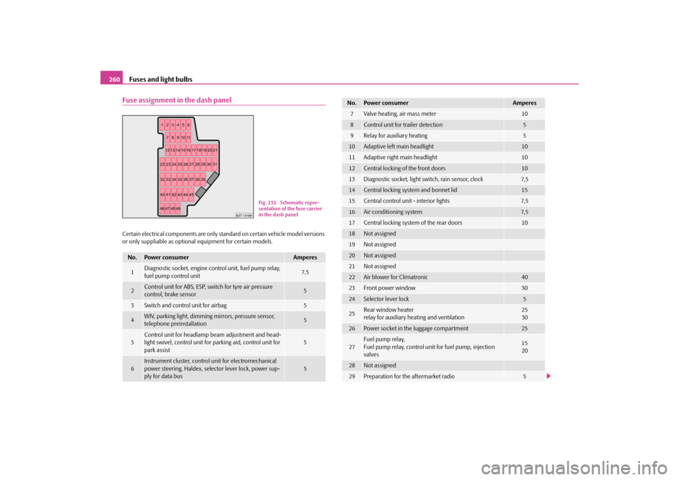
Fuse assignment in the dash panelCertain electrical components are only st
andard on certain vehicle model versions
or only suppliable as optional
equipment for certain models.
No.
Power consumer
Amperes
1
Diagnostic socket, engine control unit, fuel pump relay, fuel pump control unit
7,5
2
Control unit for ABS, ESP, switch for tyre air pressure control, brake sensor
5
3
Switch and control unit for airbag
5
4
WIV, parking light, dimming mirrors, pressure sensor, telephone preinstallation
5
5
Control unit for headlamp beam adjustment and head- light swivel, control unit for parking aid, control unit for park assist
5
6
Instrument cluster, control
unit for electromechanical
power steering, Haldex, selector lever lock, power sup- ply for data bus
5
Fig. 232 Schematic repre- sentation of the fuse carrier in the dash panel
7
Valve heating, air mass meter
10
8
Control unit for trailer detection
5
9
Relay for auxiliary heating
5
10
Adaptive left main headlight
10
11
Adaptive right main headlight
10
12
Central locking of the front doors
10
13
Diagnostic socket, light switch, rain sensor, clock
7,5
14
Central locking system and bonnet lid
15
15
Central control unit - interior lights
7,5
16
Air conditioning system
7,5
17
Central locking system of the rear doors
10
18
Not assigned
19
Not assigned
20
Not assigned
21
Not assigned
22
Air blower for Climatronic
40
23
Front power window
30
24
Selector lever lock
5
25
Rear wind
ow heater
relay for auxiliary heating and ventilation
2530
26
Power socket in the luggage compartment
25
27
Fuel pump relay, Fuel pump relay, control unit for fuel pump, injection valves
1520
28
Not assigned
29
Preparation for the aftermarket radio
5
No.
Power consumer
Amperes
s2dk.1.book Page 260 Wednesday, April 8, 2009 12:23 PM
Page 263 of 294
Fuses and light bulbs
262
WARNING
•
Bulbs H7 and H3 are pressurised and
may burst when changing the bulb
- risk of injury!•
It is recommended to wear gloves an
d eye protection when changing a
light bulb.•
Gas discharge bulbs* (xenon bulbs) op
erate with a high voltage, profes-
sional knowledge is requ
ired - danger to life!
Caution
Do not take hold of the glass bulb with naked fingers (even the smallest amount of dirt reduces the working life of the light bu
lb). Use a clean cloth, serviette or some-
thing similar.
Note
This Owner's Manual only describes the replacement of bulbs where it is assumed that no major complications will arise. Othe
r light bulbs should be changed by your
specialist garage.Front headlight
Front headlight
Halogen headlight
Xenon headlight
Low beam
H7
D1S
Main beam light
H3
D1S, H3
Parking lights
W5W
Turn signals
PY 24W
Fog lights
H8
Rear light unit
Bulb
Reversing light
W16W
Turn signals
PY21W
Light bulb for the brake lights and tail lights
W16W
Parking lights
W5W
Fog lights
P21W
Others
Bulb
Licence plate light
C5W
front interior lighting
W5W
3. Brake light
LED
Rear interior lighting
W5W
Storage compartment light - front pas- senger side
C3W
Footwell light
W5W
Luggage compartment light
W5W
Door warning light
W5W
Lighting for vanity mirror
C5W
Entry light
W5W
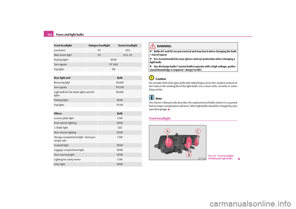
Fig. 233 Front headlight: Installing the light bulbs
s2dk.1.book Page 262 Wednesday, April 8, 2009 12:23 PM
Page 267 of 294

Fuses and light bulbs
266
Change bulbs in the outer part of the rear light unit – To change a bulb, turn its fixture to the left up to the top and take it out. – Change the bulb, insert again the fixture with the bulb into the housing
and turn it to the right up to the stop.
Change bulbs in the inner part of the rear light unit – To change a bulb of the reversing light
⇒
fig. 241
, pull the defective
bulb out of the fixture and insert a new one.
– To change the bulb of the rear fog light
⇒
fig. 241
, turn the defec-
tive bulb to the left up to the stop and take it out.
– Press a new light bulb into the socket and turn the light bulb to the
right as far as the stop.
Fitting position of the bulbs in the outer rear light unit
⇒page 265, fig. 240
.
1 - Turn signal light2 - Parking lights / Brake light3 - Parking lights Fitting position of the bulbs in the inner rear light unit
⇒fig. 241
.
1 - Reversing lights 2 - Rear fog lightLicence plate light– Unscrew the glass cover of the light
⇒
fig. 242
.
– Take the faulty bulb out of the holder and insert a new one. – Replace the the glass cover of the light and press it down to the stop -
ensure that the glass cover is correctly installed.
– Screw the glass cover tight.
Fig. 241 Inner part of the rear light unit: Lamps
A1A2
Fig. 242 Rear bumper: Licence plate light
s2dk.1.book Page 266 Wednesday, April 8, 2009 12:23 PM