change time SKODA SUPERB 2009 Owner´s Manual
[x] Cancel search | Manufacturer: SKODA, Model Year: 2009, Model line: SUPERB, Model: SKODA SUPERB 2009Pages: 252, PDF Size: 16.33 MB
Page 123 of 252
■Starting time 1 , Starting time 2 , Starting time 3 - for each pre-set time, the
day and the time (hour and minute) can be set for switching on the auxiliary
heating. An empty position can be found between Sunday and Monday when
selecting the day. If this empty position is selected, the activation is per-
formed without taking into account the day.
■ Activate - Activate pre-set mode;
■ Deactivate - Deactivate pre-set mode;
■ Factory settings - Restore factory settings
■ Back - Return to main menu
Only one programmed pre-set time can be active.
The last programmed pre-set time remains active.
After the auxiliary heating activates automatically at the set time, it is neces-
sary to pre-set a time again.
If the menu item Back is selected or no changes are made on the display for
longer than 10 seconds, the set values are stored, but the pre-set time is not
activated.
The system switches itself off at the end of the running time set under the
menu item Running time .
Note
A warning light on the button » Fig. 127 illuminates when the system is run-
ning.
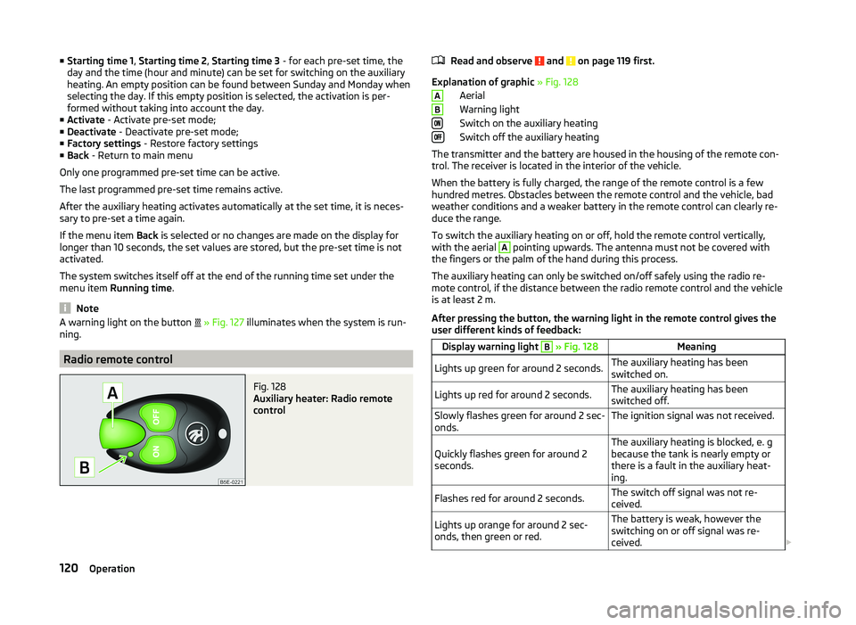
Radio remote control
Fig. 128
Auxiliary heater: Radio remote
control
Read and observe and on page 119 first.
Explanation of graphic » Fig. 128
Aerial
Warning light
Switch on the auxiliary heating
Switch off the auxiliary heating
The transmitter and the battery are housed in the housing of the remote con- trol. The receiver is located in the interior of the vehicle.
When the battery is fully charged, the range of the remote control is a few
hundred metres. Obstacles between the remote control and the vehicle, bad
weather conditions and a weaker battery in the remote control can clearly re-
duce the range.
To switch the auxiliary heating on or off, hold the remote control vertically,
with the aerial
A
pointing upwards. The antenna must not be covered with
the fingers or the palm of the hand during this process.
The auxiliary heating can only be switched on/off safely using the radio re-
mote control, if the distance between the radio remote control and the vehicle
is at least 2 m.
After pressing the button, the warning light in the remote control gives the
user different kinds of feedback:
Display warning light B » Fig. 128MeaningLights up green for around 2 seconds.The auxiliary heating has been
switched on.Lights up red for around 2 seconds.The auxiliary heating has been
switched off.Slowly flashes green for around 2 sec-
onds.The ignition signal was not received.Quickly flashes green for around 2
seconds.The auxiliary heating is blocked, e. g
because the tank is nearly empty or
there is a fault in the auxiliary heat-
ing.Flashes red for around 2 seconds.The switch off signal was not re-
ceived.Lights up orange for around 2 sec-
onds, then green or red.The battery is weak, however the
switching on or off signal was re-
ceived. AB120Operation
Page 129 of 252
Call register
The following menu items can be selected in the Call register menu item.
■ Missed calls - List of missed calls
■ Dialled nos. - List of dialled numbers
■ Received calls - list of received calls
Voice mailbox
In the Voice mailbox menu item, you can set the number of the voice mailbox 1)
and then dial the number.
Bluetooth
The following menu items can be selected from the Bluetooth menu item.
■ User - Overview of the stored telephones
■ New user - Search for new mobile phones in reception range
■ Visibility - Switches on the visibility of the hands-free system for other devi-
ces
■ Media player - Playback via Bluetooth ®
■ Active device - Connected device
■ Paired devices - List of paired devices
■ Find - Device search
■ Phone name - option to change the name of the phone (default SKODA_BT)
Settings
The following menu items can be selected from the Settings menu item.
■ Phone book - Phonebook
■ Update 1)
- Update the phone book
■ List - Arrange the entries in the phone book
■ Surname - Arrange according to surname
■ Surname - Sort by contact name
■ Ring tone - Ring tone setting
Back
Return to the telephone's basic menu.Universal telephone preinstallation GSM IIl
Introduction
This chapter contains information on the following subjects:
Connecting the phone to the hands-free system
127
Telephone operation in the MAXI DOT display
128
Internet connection via Bluetooth ®
129
The universal telephone preinstallation GSM III comprises the following func-
tions.
› Phone Phonebook
» page 124.
› Convenience operation via the multifunction steering wheel
» page 122.
› Telephone operation in the MAXI DOT display
» page 128.
› Voice control of the telephone
» page 131.
› Music playback from the telephone or other multimedia units
» page 134.
› Internet connection
» page 129.
› Display of SMS messages
» page 128.
All communication between a telephone and the hands-free system of your vehicle can only be established with the help of the following profiles of Blue-
tooth ®
technology.
rSAP - Remote SIM access profile
After connecting the telephone with the hands-free system via the rSAP pro-
file, the telephone deregisters from the GSM network, and communication
with the network is only enabled by the hands-free system via the vehicle's
external aerial. In the telephone only the interface for Bluetooth ®
remains ac-
tive. In this case, you can only use the mobile phone to disconnect from the
hands-free system, deactivate the Bluetooth ®
connection or dial the emergen-
cy number 112 (only valid in some countries).
HFP - Hands Free Profile
After connecting the telephone with the hands-free system via the HFP pro-
file, the telephone continues to use its GSM module and the internal antenna
to communicate with the GSM network.
1)
On vehicles fitted with the Amundsen+ navigation system, this function can be accessed via the naviga-
tion system menu; refer to the » Operating instructions for the Amundsen+ navigation system .
126Operation
Page 132 of 252

■Search - Search for available media players
■ Visibility - Switch on the visibility of the hands-free system for media play-
ers in the vicinity
■ Modem - overview of the active and paired devices for the connection to the
internet
■ Active device - Connected device
■ Paired devices - List of paired devices
■ Phone name - option to change the name of the phone (default SKODA_BT)
WLAN
Wi-Fi menu item » page 131, Use WLAN network in MAXI DOT display .
Settings
The following menu items can be selected from the Settings menu item.
■ Phone book - Phonebook
■ Update - Read in the phone book
■ Select memory - Select memory with phone contacts
■ SIM & phone - Download the contacts of the SIM card and the phone
■ SIM card - Download the contacts from the SIM card
■ Phone - Initial setting to also import contacts from the SIM card; it is nec-
essary to switch to the SIM & phone menu item
■ List - Arrange the entries in the phone book
■ Surname - Arrange according to surname
■ Surname - Sort by contact name
■ Own number - Optionally display your own telephone number on the display
of the device of the person you are calling (this function is network-depend-
ent) ■ Network depnd. - Network-dependent own number display
■ Yes - Allow display of your own number
■ No - Prohibit display of your own number
■ Signal settings - Signal settings
■ Ring tone - Ring tone setting
■ Volume - Signal volume settings
■ Turn vol. up - Increase volume
■ Turn vol. down - Decrease volume
■ Phone settings - Phone settings
■ Select operator - Select operator
■ Automatic - Automatic operator selection
■ Manual - Manual operator selection■
Network mode - Network mode
■ UMTS - UMTS
■ GSM - GSM
■ Automatic - automatic
■ SIM mode - Applies to telephones with the rSAP profile that simultaneously
support the operation of two SIM cards - there is an option to choose which
SIM card to connect to the hands-free system
■ SIM mode 1 - SIM 1 is connected to the hands-free system
■ SIM mode 2 - SIM 2 is connected to the hands-free system
■ Phone mode - Toggle between rSAP and HFP mode
■ Premium - rSAP mode
■ Hands-free - HFP mode
■ Off time - Set the off time in increments of 5 min
■ Access point - Set the Internet access point
■ APN - Change the access point name
■ User name - User Name
■ Password - Password
■ Switch off ph. - Switch off the hands-free system (the mobile phone remains
paired)
Back
Return to the main menu in the MAXI DOT display.
Internet connection via Bluetooth ®
A notebook can, for example, be connected to the Internet via the hands-free
system.
The control unit of the hands-free system supports the GPRS, EDGE and
UMTS/3G technologies.
An Internet can only be established via a telephone which is connected via the rSAP profile.
The procedure for connecting to the Internet can vary depending on the type
and version of the operating system as well as the type of the device to be
connected. Successfully connecting to the internet requires appropriate
knowledge of the operating system for connecting the device .
Sequence for connection
›
Connect the mobile phone with the hands-free system.
›
Set the access point in the Phone - Settings - Access point menu (depending
on the operator, usually “Internet”).
129Communication and multimedia
Page 134 of 252
If the Pushbutton menu item is selected in the instrument cluster, the Wi-Fi
connection is made automatically.
If the WPS PIN menu item is selected in the instrument cluster, then a PIN
must be entered in the device to be connected and the instrument cluster.
Use WLAN network in MAXI DOT display
When a Wi-Fi network is switched on, the following menu items are displayed
when the Wi-Fi menu item is selected:
■ Off - Switch off the WLAN network (depending on the context)
■ Device list - Display a list of external devices
■ Active device - Display a list of active devices
■ Block - Block device connections
■ Known devices - Display a list of known devices
■ Rename - Rename the device
■ Block - Block device connections
■ Device blocked - Display of a list of blocked devices
■ Unblock - Remove the connection block
■ Delete lists - Delete device lists
■ Known devices - Delete the list of known devices
■ Device blocked - Delete the list of blocked devices
■ Both lists - Delete both device lists
■ Password - Use of password to log on to the WLAN network
■ Show - Display a password to log on to the WLAN network
■ Generate - Generate a new password to log on to the WLAN network
■ Wi-Fi Name - Use of WLAN network name
■ Show - Display the WLAN network name
■ Rename - Rename the WLAN network
■ WPS config. - Wi-Fi network connection using WPS
■ Pushbutton - Automatic connection
■ WPS PIN - PIN entry for the connection
■ Data counter - Display information about the volume of data transferred
■ Current Connection - display of the volume of data transferred for the cur-
rent connection
■ Total - Display of the total volume of data transferred
■ Reset - Resetting of the information about the volume of data transferred
■
Settings - WLAN network settings
■ Access point - Access point settings
■ Settings - Access point management
■ APN - Change the access point name
■ User name - User Name
■ Password - Password
■ Reset - Reset access point factory settings
■ Prioritisation - Set the connection priority
■ Calls - Set the connection priority for calls
■ Data - Set the connection priority for data transfer
■ Encryption - Set the encryption
■ WPA2 - Enable WPA 2 encryption
■ Open - No encryption
■ Visibility - Set the WLAN network visibility
■ Visible - WLAN network is visible to other devices
■ Invisible - WLAN network is not visible to other devices
■ Data roaming - Set the data roaming
■ No roaming - Data roaming is not allowed
■ Allow - Data roaming is allowed
■ Always ask - Question setting for data roaming
■ Wi-Fi Channel - Select WLAN network channels (preferably set to channel
11) ■ Channel 1 ... Channel 11 - Display the WLAN network channels
■ Reset - Reset Wi-Fi network factory settings
Voice control
Introduction
This chapter contains information on the following subjects:
Dialogue
132
Voice commands - GSM II
133
Voice commands - GSM III
133131Communication and multimedia
Page 137 of 252
Multimedia
Introduction
This chapter contains information on the following subjects:
Music playback via Bluetooth ®
134
Operating the radio and navigation system on the multifunction steering
wheel
134
AUX- and MDIinputs
135
CD changer
136
DVD-preinstallation
136
Music playback via Bluetooth ®
The universal telephone preinstallation makes it possible to play back music
via Bluetooth ®
from devices such as MP3 players, mobile phones or notebooks.
To ensure the music can be played back via Bluetooth ®
, you must first pair the
device with the hands-free system in the Phone - Bluetooth - Media player
menu.
The music playback process is performed on the connected device.
The universal telephone preinstallation GSM II ensures that the music played
back via the hands-free system can be controlled with the remote con-
trol » page 133 , Voice commands - GSM II .
Note
The device being connected must support the Bluetooth ®
A2DP profile; refer
to the operating instructions for the relevant device being connected.
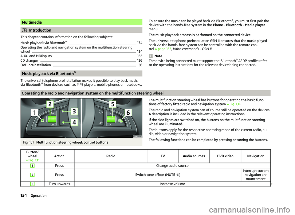
Operating the radio and navigation system on the multifunction steering wheel
Fig. 131
Multifunction steering wheel: control buttons
The multifunction steering wheel has buttons for operating the basic func-
tions of factory fitted radio and navigation system » Fig. 131.
The radio and navigation system can of course still be operated on the devices. A description is included in the relevant operating instructions.
If the side lights are switched on, the buttons on the multifunction steering wheel are illuminated.
The buttons apply for the respective operating mode of the current radio, au-
dio, video or navigation system.
The following functions can be completed by pressing or turning the buttons.Button/ wheel
» Fig. 131ActionRadioTVAudio sourcesDVD videoNavigation
1PressChange audio source2
PressSwitch tone off/on (MUTE
)Interrupt current
navigation an-nouncement2Turn upwardsIncrease volume 134Operation
Page 140 of 252

WARNING■If there are passengers on the rear seats, the DVD player holder must not
be used on its own (without the DVD player) - risk of injury!■
The inclination of the holder can be adjusted to three pre-set positions.
Be careful not to injure fingers between the holder and the backrest when
changes to the position of the DVD player holder are made.
■
The DVD player holder must not be used when the rear seat backrest or
the rear seat is folded forward or has been removed completely.
Note
Follow the instructions given in the operating instructions of the DVD player
holder/DVD player.137Communication and multimedia
Page 157 of 252
Assist systems
Brake assist systems
Introduction
This chapter contains information on the following subjects:
Electronic Stability Control (ESC)
154
Antilock brake system (ABS)
155
Traction Control System (ASR)
155
Electronic Differential Lock (EDL)
155
Driver Steering Recommendation (DSR)
155
Hydraulic Brake Assist (HBA)
155
Hill Hold Control (HHC)
156WARNING■ A lack of fuel can cause irregular engine running or cause the engine to
shut down. The brake assist systems would then fail to function – risk of
accident!■
Adjust the speed and driving style to the current visibility, weather, road
and traffic conditions. The increased safety provided by the brake assist
systems must not tempt you to take safety risks – risk of accident!
■
In the event of an ABS fault, visit a specialist garage immediately. Adjust
your style of driving according to the damage to the ABS, as you will not
know the exact extent of the damage or the extent to which this is limiting the braking efficiency.
CAUTION
■ All four wheels must be fitted with the same tyres approved by the manufac-
turer to ensure the brake assist systems operate correctly.■
Changes to the vehicle (e.g. to the engine, brakes, chassis) can influence the
functionality of the brake assist systems » page 173, Services, modifications
and technical alterations .
■
If a fault occurs in the ABS system, the ESC, ASR and EDL will also not work.
An ABS fault is indicated with the warning light
» page 38 .
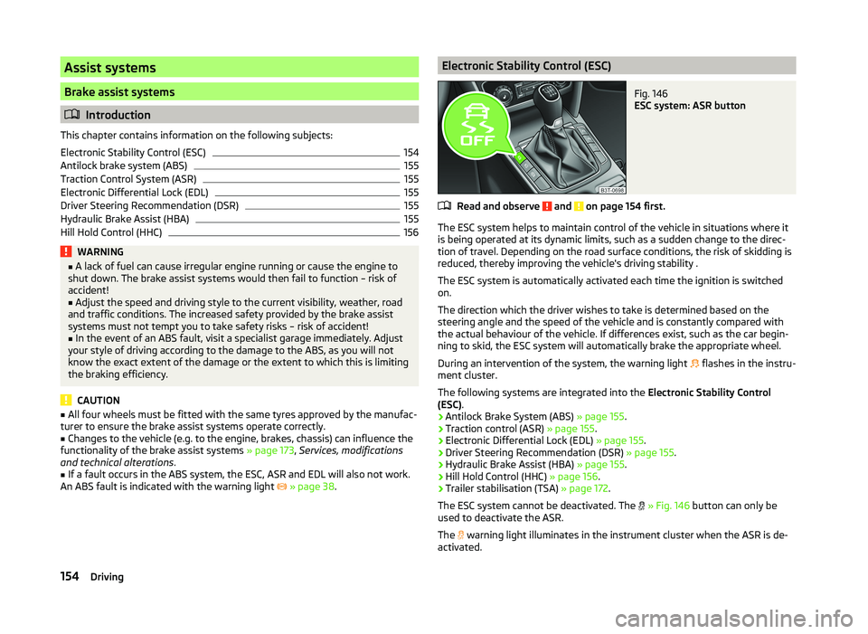
Electronic Stability Control (ESC)Fig. 146
ESC system: ASR button
Read and observe and on page 154 first.
The ESC system helps to maintain control of the vehicle in situations where it
is being operated at its dynamic limits, such as a sudden change to the direc-
tion of travel. Depending on the road surface conditions, the risk of skidding is
reduced, thereby improving the vehicle's driving stability .
The ESC system is automatically activated each time the ignition is switched on.
The direction which the driver wishes to take is determined based on the
steering angle and the speed of the vehicle and is constantly compared with
the actual behaviour of the vehicle. If differences exist, such as the car begin-
ning to skid, the ESC system will automatically brake the appropriate wheel.
During an intervention of the system, the warning light flashes in the instru-
ment cluster.
The following systems are integrated into the Electronic Stability Control
(ESC) .
› Antilock Brake System (ABS)
» page 155.
› Traction control (ASR)
» page 155.
› Electronic Differential Lock (EDL)
» page 155.
› Driver Steering Recommendation (DSR)
» page 155.
› Hydraulic Brake Assist (HBA)
» page 155.
› Hill Hold Control (HHC)
» page 156.
› Trailer stabilisation (TSA)
» page 172.
The ESC system cannot be deactivated. The
» Fig. 146 button can only be
used to deactivate the ASR.
The warning light illuminates in the instrument cluster when the ASR is de-
activated.
154Driving
Page 162 of 252
The display shows the following » Fig. 149 - .
The search area for the parking space on the driver's side is automatically indi- cated on the display.
Activate the turn signal on the driver's side if you wish to park on this side of
the road. In the display the search area for the parking space is indicated on
the driver's side.
If suitable parking space is found, its parameters are stored until another suit-
able parking space has been found or until a distance of 10 m had been driven
after finding the parking space.
If the driver changes the parking mode while searching for a parking space, the
symbol button must be pressed again.
Note
If the symbol
(km / h) is shown in the display , the vehicle speed should be
reduced below 40 km / hr (parallel parking) or below 20 km / hr (Transverse
parking) .
Parking
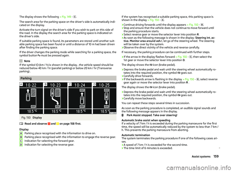
Fig. 150
Display
Read and observe
and on page 158 first.
Display Parking place recognised with the information to drive on.
Parking place recognised with the information to engage the reverse gear.
Indication for selecting the forward gear.
Indication for selecting the reverse gear.
ABCDIf the system has recognised a suitable parking space, this parking space is
shown in the display » Fig. 150 - .›
Continue driving forwards until the display appears » Fig. 150 -
.
›
Stop and ensure that the vehicle does not continue to move forward until
the parking procedure starts.
›
Select reverse gear or move the selector lever into position R.
›
As soon as the following message is shown in the display: Steering int. ac-
tive. Monitor area around veh.! , let go of the steering wheel. The steering
will be taken over by the system.
›
Observe the direct vicinity of the vehicle and reverse carefully.
If necessary, the parking procedure can be continued with further steps.
›
If the arrow in the display flashes forward » Fig. 150 -
, then select the
1st gear or move the selector lever into position D.
The display shows the icon (brake pedal).
›
Depress the brake pedal and wait until the steering wheel automatically ro-
tates into the required position, the symbol goes out.
›
Carefully drive forwards.
›
If the backwards arrow is flashing in the display
» Fig. 150 -
, select reverse
gear again or move the selector lever into position R .
The display shows the icon (brake pedal).
›
Depress the brake pedal and wait until the steering wheel automatically ro-
tates into the required position, the symbol goes out.
›
Carefully move backwards.
You can repeat these steps several times in succession.
As soon as the parking procedure is completed, an audible signal sounds and
the following message appears in the display.
Park Assist stopped. Take over steering!
Automatic brake assist when speeding
If a velocity of 7 km / h is exceeded during the parking manoeuvre for the first time, the speed will be automatically reduced by the system to less than 7 km /
h. This prevents the parking manoeuvre from aborting.
Automatic termination
The system terminates the parking procedure if one of the following cases ari-
ses.
› A speed of 7 km / h is exceeded for the second time.
› The time limit of 6 minutes is exceeded.
159Assist systems
Page 169 of 252
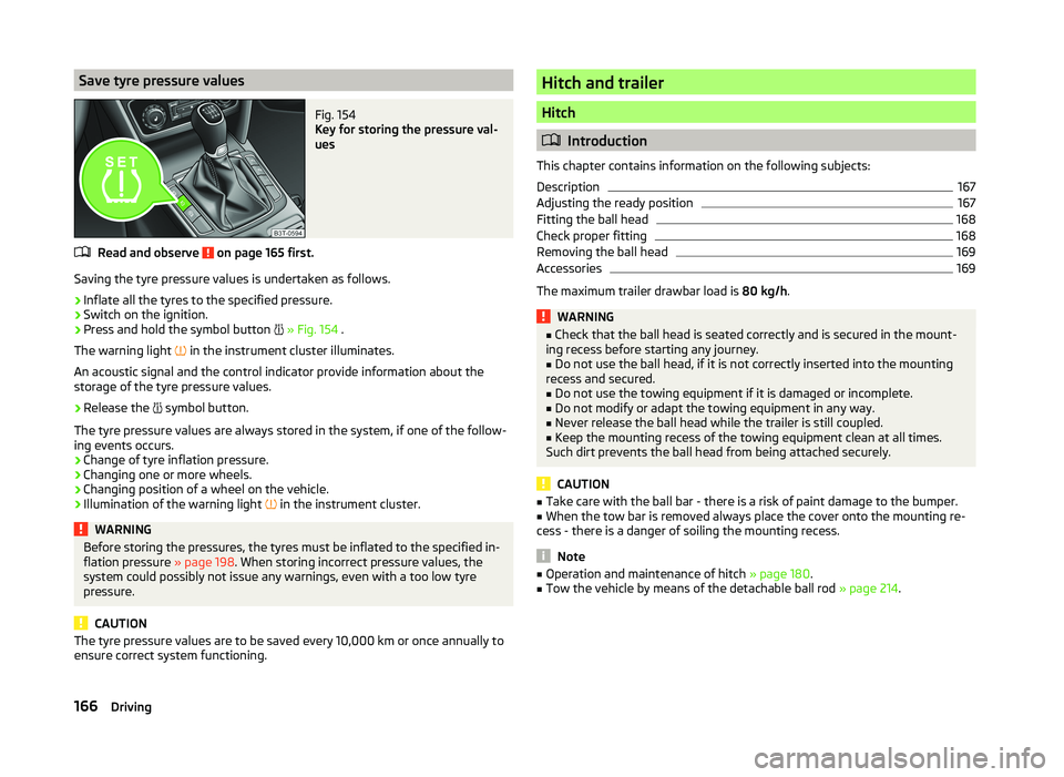
Save tyre pressure valuesFig. 154
Key for storing the pressure val-
ues
Read and observe on page 165 first.
Saving the tyre pressure values is undertaken as follows.
›
Inflate all the tyres to the specified pressure.
›
Switch on the ignition.
›
Press and hold the symbol button
» Fig. 154 .
The warning light in the instrument cluster illuminates.
An acoustic signal and the control indicator provide information about the
storage of the tyre pressure values.
›
Release the symbol button.
The tyre pressure values are always stored in the system, if one of the follow-
ing events occurs.
› Change of tyre inflation pressure.
› Changing one or more wheels.
› Changing position of a wheel on the vehicle.
› Illumination of the warning light
in the instrument cluster.
WARNINGBefore storing the pressures, the tyres must be inflated to the specified in-
flation pressure » page 198. When storing incorrect pressure values, the
system could possibly not issue any warnings, even with a too low tyre
pressure.
CAUTION
The tyre pressure values are to be saved every 10,000 km or once annually to
ensure correct system functioning.Hitch and trailer
Hitch
Introduction
This chapter contains information on the following subjects:
Description
167
Adjusting the ready position
167
Fitting the ball head
168
Check proper fitting
168
Removing the ball head
169
Accessories
169
The maximum trailer drawbar load is 80 kg/h.
WARNING■
Check that the ball head is seated correctly and is secured in the mount-
ing recess before starting any journey.■
Do not use the ball head, if it is not correctly inserted into the mounting
recess and secured.
■
Do not use the towing equipment if it is damaged or incomplete.
■
Do not modify or adapt the towing equipment in any way.
■
Never release the ball head while the trailer is still coupled.
■
Keep the mounting recess of the towing equipment clean at all times.
Such dirt prevents the ball head from being attached securely.
CAUTION
■ Take care with the ball bar - there is a risk of paint damage to the bumper.■When the tow bar is removed always place the cover onto the mounting re-
cess - there is a danger of soiling the mounting recess.
Note
■ Operation and maintenance of hitch » page 180.■Tow the vehicle by means of the detachable ball rod » page 214.166Driving
Page 172 of 252

Removing the ball headFig. 159
Unlock the operating lever of the ball head/removing the ball
head
Read and observe
and on page 166 first.
›
Remove cover
1
» Fig. 159 from the lock in the direction of the arrow.
›
Insert the key into the lock, so that its green marking is pointing upwards.
›
Turn the key
2
180° to the left so that its red marker points upward.
›
Grasp the ball head from underneath.
›
Press the release pin
3
as far as the stop in the direction of the arrow and
at the same time push the lever
4
downwards as far as it will go in the di-
rection of the arrow.
The ball head is released in this position and falls freely into the hand. If it
does not fall freely into the hand, use your other hand to push it upwards.
At the same time, the ball head latches into the ready position and is thus
ready to be re-inserted into the mounting recess »
.
›
Place the cap
4
» Fig. 155 on page 167 onto the mounting recess.
WARNINGNever allow the ball head to remain unsecured in the boot. This could
cause damage to the boot upon sudden braking, and could put the safety
of the occupants at risk.CAUTION■ If the lever is held firmly and not pushed downwards as far as it can go, it will
go back up after the ball head is removed and will not latch into the ready po-
sition. The ball head then needs to be brought into this position before the
next time it is fitted.■
Tuck the ball bar in the ready position, with the golden key up, in the box -
otherwise there is a risk of damage to the key!
■
Do not use excessive force when handling the operating lever (e.g. do not
step on it).
Note
■ We recommend that you put the protective cap on the ball before removing
the ball head.■
Clean any dirt from the ball head before stowing it away in the box with the
vehicle tool kit.
Accessories
Fig. 160
Representation of the maximum
permissible level of the ball head
of the towing hitch and the per-
missible total weight of the ac-
cessories including the load de-
pending on the load center of
gravity
Read and observe and on page 166 first.
An accessory can mounted on the ball head of the towing hitch (e.g. bike carri-
ers).
If this accessory is used, the maximum permissible overhang of the ball head
of the towing hitch and the permissible gross vehicle weight of the accesso-
ries including load are to be checked.
The maximum permissible overhang of the ball head of the towing hitch is 70
cm » Fig. 160 .
The total permitted weight of the accessory including load changes with in-
creasing distance of the centre of gravity of the load from the ball head of the
towing hitch.
169Hitch and trailer