change time SKODA SUPERB 2009 Owner´s Manual
[x] Cancel search | Manufacturer: SKODA, Model Year: 2009, Model line: SUPERB, Model: SKODA SUPERB 2009Pages: 252, PDF Size: 16.33 MB
Page 185 of 252
■Sharp-edged objects on items of clothing such as zip fasteners, rivets, sharp-
edged belts, jewellery and pendants may leave permanent scratches or signs
of rubbing on the surface. Such damage cannot be subsequently recognised as
a justified complaint.■
The use of an additional mechanical steering wheel lock may damage the
leather surface of the steering wheel.
■
Use a care cream with light blocker and impregnation effect on a regular ba-
sis and each time after cleaning. The cream nourishes the leather, allows it to
breathe and keeps it supple and also provides moisture. It also creates surface
protection.
■
Some clothing materials, e.g. dark denim, do not have sufficient colour fast-
ness. This can cause damage or clearly visible discolouration to seat covers,
even when used correctly. This applies particularly to light-coloured seat cov-
ers. This does not relate to a fault in the seat cover, but rather to poor colour
fastness of the clothing textiles.
Note
When using the vehicle, minor visible changes may occur to the leather parts
of the covers (e.g. wrinkles or creases) as a result of the stress applied to the
covers.
Synthetic leather, fabrics and Alcantara ®
Read and observe
and on page 181 first.
Artificial leather
Clean artificial leather with a damp cloth.
If this method does not completely clean the artificial leather, use a mild soap
solution or cleaning products specially designed for this purpose.
Fabric
Clean upholstery cover materials and cloth trims on doors, boot cover, etc. us-
ing specific cleaning agents, e.g., dry foam.
Use a soft sponge, brush, or commercially available microfibre cloth.
Use a cloth and special detergent to clean the headlining.
Remove any lumps on the cover fabric and any fabric residue using a brush.
Remove stubborn hair using a “cleaning glove”.
Alcantara ®
Dust and fine dirt particles in pores, creases and seams may chafe and damage
the surface.
If you leave your vehicle parked in the open for lengthy periods, protect the Al-
cantara ®
seat upholstery from direct sunlight to prevent fading.
Minor changes in colour caused by use are normal.
CAUTION
■ Do not use leather cleaners on Alcantara ®
seat upholstery.■Do not use solvents, floor wax, shoe cream, stain remover or similar agents
on Alcantara ®
seat upholstery.■
Avoid leaving the vehicle in bright sunlight for long periods of time in order
to stop the fabric from bleaching. If the vehicle is parked outside for long peri-
ods of time, cover the fabric to protect it from direct sunlight.
■
Some clothing materials, e.g. dark denim, do not have sufficient colour fast-
ness. This can cause damage or clearly visible discolouration to seat covers,
even when used correctly. This applies particularly to light-coloured seat cov-
ers. This does not relate to a fault in the seat cover, but rather to poor colour
fastness of the clothing textiles.
Seat covers
Read and observe
and on page 181 first.
Electrically heated seats
Do not clean the covers by moistening, as this can damage the seat heating
system.
Use a specific cleaning agent such as dry foam or similar to clean the covers.
Seats without seat heating
Thoroughly vacuum the seat covers with a vacuum cleaner before cleaning.
Clean the seat covers with a damp cloth or cleaning products specially de-
signed for this purpose.
Indented points arising on the fabrics by everyday use, can be removed by
brushing against the direction of hair with a damp brush.
Always clean all parts of the covers, so that there are no visible edges. Then
allow the seat to dry completely.
CAUTION
■ Regularly remove dust from the seat covers using a vacuum cleaner.■Electrically heated seats must not be dried after cleaning by switching on the
heater. 182General Maintenance
Page 192 of 252
CAUTION■Under no circumstances must radiator antifreeze or other additives be added
to the windscreen washer fluid.■
If the vehicle is fitted with a headlight cleaning system, only cleaning prod-
ucts which do not attack the polycarbonate coating of the headlights must be
added to the windscreen washer fluid.
■
Do not remove the filter from the windscreen washer fluid reservoir when re-
filling, as this may cause contamination of the liquid transportation system,
leading in turn to a windscreen washer system malfunction.
Engine oil
Introduction
This chapter contains information on the following subjects:
Specifications and capacity
189
Checking the oil level
190
Replenishing
191
The engine has been factory-filled with a high-grade oil that can be use
throughout the year - except in extreme climate zones.
The engine oils are undergoing continuous further development. Thus the in- formation stated in this Owner's Manual is only correct at the time of publica-
tion.
ŠKODA Service Partners are informed about the latest changes by the manu-
facturer. We therefore recommend that the oil change be completed by a
ŠKODA Service Partner.
The specifications (VW standards) stated in the following can be indicated sep-
arately or together with other specifications on the bottle.
The oil capacities include oil filter change. Check the oil level when filling; do
not over fill. The oil level must be between the markings » page 190.
WARNING■
The engine compartment of your car is a hazardous area. The following
warning instructions must be followed at all times when working in the en-
gine compartment » page 186.■
Stop driving if for some reason it is not possible to top up the engine
oil under the current conditions. Switch off the engine and seek assistance
from a specialist garage.
■
Do not drive on if the oil level is above range
A
» Fig. 166 on
page 190 . Switch off the engine and seek assistance from a specialist ga-
rage.
CAUTION
Do not pour any additives into the engine oil – risk of serious damage to the
engine parts!
Note
■ Before a long drive we recommend that you purchase and carry with you en-
gine oil which complies with the specification for your vehicle.■
We recommend that you use oils from ŠKODA Original Accessories.
■
If oil comes into contact with your skin, the affected area must be washed
thoroughly.
Specifications and capacity
Read and observe
and on page 189 first.
Specifications and capacity (in l) for vehicles with flexible service intervals
Petrol enginesSpecificationCapacity1.4 l/92 kW TSIVW 503 00, VW 504 003.61.8 l/112, 118 kW TSIVW 504 004.62.0 l/147 kW TSIVW 504 004.63.6 l/191 kW FSIVW 504 005.5Diesel engines a)SpecificationCapacity1.6 l/77 kW TDI CRVW 507 004.32.0 ltr/103 kW TDI CR DPFVW 507 004.32.0 ltr/125 kW TDI CR DPFVW 507 004.3a)
Engine oil VW 505 01 can optionally be used in diesel engines
without DPF
189Inspecting and replenishing
Page 193 of 252
Specifications and capacity (in l) for vehicles with fixed service intervalsPetrol enginesSpecificationCapacity1.4 l/92 kW TSIVW 501 01, VW 502 003.6
1.8 l/112, 118 kW TSI
VW 502 00
4.6
applies to RussiaSAE 0W-30
VW 502 00 / 505 00
2.0 l/147 kW TSI
VW 502 00
4.6
applies to Russia SAE 0W-30
VW 502 00 / 505 003.6 l/191 kW FSIVW 502 005.5Diesel engines a)SpecificationCapacity1.6 l/77 kW TDI CRVW 507 004.32.0 ltr/103 kW TDI CR DPFVW 507 004.32.0 ltr/125 kW TDI CR DPFVW 507 004.3a)
Engine oil VW 505 01 can optionally be used in diesel engines
without DPF
CAUTION
■
If the above engine oils are not available, a different engine oil can be used in
an emergency. To prevent damage to the engine, a maximum of 0.5 litres only
of the following engine oils may be used until the next oil change: ■ For petrol engine models: ACEA A3/ACEA B4 or API SN/API SM;
■ For diesel engine models: ACEA C3 or API CJ-4.
Checking the oil level
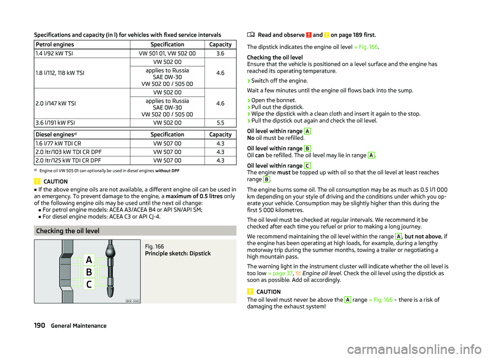
Fig. 166
Principle sketch: Dipstick
Read and observe and on page 189 first.
The dipstick indicates the engine oil level » Fig. 166.
Checking the oil level
Ensure that the vehicle is positioned on a level surface and the engine has
reached its operating temperature.
›
Switch off the engine.
Wait a few minutes until the engine oil flows back into the sump.
›
Open the bonnet.
›
Pull out the dipstick.
›
Wipe the dipstick with a clean cloth and insert it again to the stop.
›
Pull the dipstick out again and check the oil level.
Oil level within range
A
No oil must be refilled.
Oil level within range
B
Oil can be refilled. The oil level may lie in range
A
.
Oil level within range
C
The engine must be topped up with oil so that the oil level at least reaches
range
B
.
The engine burns some oil. The oil consumption may be as much as 0.5 l/1 000
km depending on your style of driving and the conditions under which you op-
erate your vehicle. Consumption may be slightly higher than this during the
first 5 000 kilometres.
The oil level must be checked at regular intervals. We recommend it be
checked after each time you refuel or prior to making a long journey.
We recommend maintaining the oil level within the range
A
, but not above , if
the engine has been operating at high loads, for example, during a lengthy
motorway trip during the summer months, towing a trailer or negotiating a
high mountain pass.
The warning light in the instrument cluster will indicate whether the oil level is
too low » page 37 ,
Engine oil level
. Check the oil level using the dipstick as
soon as possible. Add oil accordingly.
CAUTION
The oil level must never be above the A range » Fig. 166 – there is a risk of
damaging the exhaust system!190General Maintenance
Page 196 of 252
WARNING■The engine compartment of your car is a hazardous area. The following
warning instructions must be followed at all times when working in the en-
gine compartment » page 186.■
Do not continue your journey if the fluid level has fallen below the MIN
marking » Fig. 168 on page 193 - there is a risk of an accident. Seek help
from a specialist garage.
■
Do not use used brake fluid - the function of the brake system may be im-
paired – risk of accident!
CAUTION
Brake fluid damages the paintwork of the vehicle.
Note
■ The brake fluid is changed as part of a compulsory inspection service.■We recommend using brake fluids from the ŠKODA Original Accessories
range.
Checking the brake fluid level
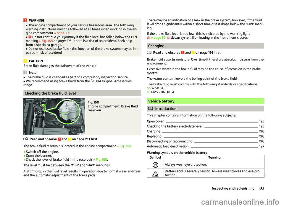
Fig. 168
Engine compartment: Brake fluid
reservoir
Read and observe and on page 193 first.
The brake fluid reservoir is located in the engine compartment » Fig. 168.
›
Switch off the engine.
›
Open the bonnet.
›
Check the level of brake fluid in the reservoir » Fig. 168.
The level must be between the “MIN” and “MAX” markings.
A slight drop in the fluid level results in operation due to normal wear-and-tear
and the automatic adjustment of the brake pads.
There may be an indication of a leak in the brake system, however, if the fluid
level drops significantly within a short time or if it drops below the “MIN” mark- ing.
If the brake fluid level is too low, this is indicated by the warning light
» page 35 ,
Brake system illuminating in the instrument cluster.
Changing
Read and observe
and on page 193 first.
Brake fluid absorbs moisture. Over time it therefore absorbs moisture from the
environment.
Excessive water in the brake fluid may be the cause of corrosion in the brake
system.
The water content lowers the boiling point of the brake fluid.
The brake fluid must comply with the following standards or specifications: › VW 50114;
› FMVSS 116 DOT4.
Vehicle battery
Introduction
This chapter contains information on the following subjects:
Open cover
195
Checking the battery electrolyte level
195
Charging
196
Replacing
196
Disconnecting or reconnecting
196
Automatic load deactivation
197
Warning symbols on the vehicle battery
SymbolMeaningAlways wear eye protection.Battery acid is severely caustic. Always wear gloves and eye pro-
tection. 193Inspecting and replenishing
Page 213 of 252
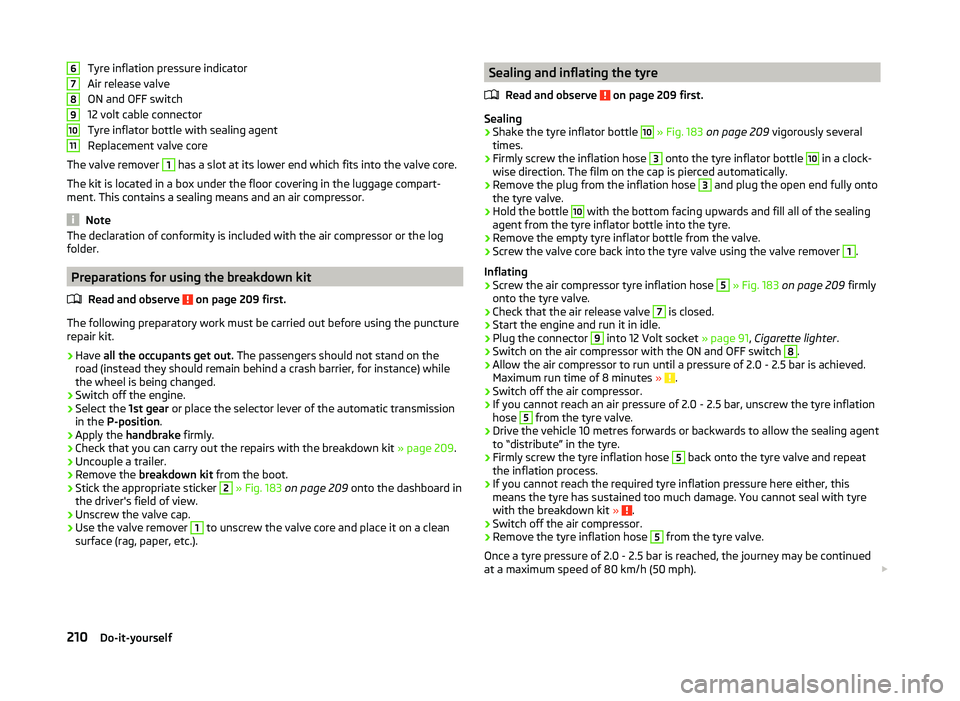
Tyre inflation pressure indicator
Air release valve
ON and OFF switch
12 volt cable connector
Tyre inflator bottle with sealing agent
Replacement valve core
The valve remover 1
has a slot at its lower end which fits into the valve core.
The kit is located in a box under the floor covering in the luggage compart-
ment. This contains a sealing means and an air compressor.
Note
The declaration of conformity is included with the air compressor or the log
folder.
Preparations for using the breakdown kit
Read and observe
on page 209 first.
The following preparatory work must be carried out before using the puncturerepair kit.
›
Have all the occupants get out. The passengers should not stand on the
road (instead they should remain behind a crash barrier, for instance) while
the wheel is being changed.
›
Switch off the engine.
›
Select the 1st gear or place the selector lever of the automatic transmission
in the P-position .
›
Apply the handbrake firmly.
›
Check that you can carry out the repairs with the breakdown kit
» page 209.
›
Uncouple a trailer.
›
Remove the breakdown kit from the boot.
›
Stick the appropriate sticker
2
» Fig. 183 on page 209 onto the dashboard in
the driver's field of view.
›
Unscrew the valve cap.
›
Use the valve remover
1
to unscrew the valve core and place it on a clean
surface (rag, paper, etc.).
67891011Sealing and inflating the tyre
Read and observe
on page 209 first.
Sealing
›
Shake the tyre inflator bottle
10
» Fig. 183 on page 209 vigorously several
times.
›
Firmly screw the inflation hose
3
onto the tyre inflator bottle
10
in a clock-
wise direction. The film on the cap is pierced automatically.
›
Remove the plug from the inflation hose
3
and plug the open end fully onto
the tyre valve.
›
Hold the bottle
10
with the bottom facing upwards and fill all of the sealing
agent from the tyre inflator bottle into the tyre.
›
Remove the empty tyre inflator bottle from the valve.
›
Screw the valve core back into the tyre valve using the valve remover
1
.
Inflating
›
Screw the air compressor tyre inflation hose
5
» Fig. 183 on page 209 firmly
onto the tyre valve.
›
Check that the air release valve
7
is closed.
›
Start the engine and run it in idle.
›
Plug the connector
9
into 12 Volt socket » page 91, Cigarette lighter .
›
Switch on the air compressor with the ON and OFF switch
8
.
›
Allow the air compressor to run until a pressure of 2.0 - 2.5 bar is achieved.
Maximum run time of 8 minutes » .
›
Switch off the air compressor.
›
If you cannot reach an air pressure of 2.0 - 2.5 bar, unscrew the tyre inflation
hose
5
from the tyre valve.
›
Drive the vehicle 10 metres forwards or backwards to allow the sealing agent
to “distribute” in the tyre.
›
Firmly screw the tyre inflation hose
5
back onto the tyre valve and repeat
the inflation process.
›
If you cannot reach the required tyre inflation pressure here either, this
means the tyre has sustained too much damage. You cannot seal with tyre with the breakdown kit »
.
›
Switch off the air compressor.
›
Remove the tyre inflation hose
5
from the tyre valve.
Once a tyre pressure of 2.0 - 2.5 bar is reached, the journey may be continued
at a maximum speed of 80 km/h (50 mph).
210Do-it-yourself
Page 218 of 252
If the towing device is removed completely, it must be replaced with the
standard reinforcement of the rear bumper which is part of the mount for the
towing eye.
If this procedure is not observed, the vehicle may not meet the national legal
provisions.
CAUTION
The detachable ball rod and/or the vehicle can be damaged if an unsuitable
tow bar is used.
Note
The detachable ball rod must always be in the vehicle so that it can be used for
towing, if necessary.
Radio remote control
Introduction
This chapter contains information on the following subjects:
Replacing the battery in the remote control key
215
Synchronising the remote control
215
Replace the battery in the remote control of the auxiliary heater (parking
heater)
216
CAUTION
■ The replacement battery must have the same specification as the original
battery.■
We recommend having faulty batteries replaced by a ŠKODA service partner.
■
Pay attention to the correct polarity when changing the battery.
For the sake of the environment
Dispose of the used battery in accordance with national legal provisions.Replacing the battery in the remote control keyFig. 190
Remove cover/take out battery
Read and observe
on page 215 first.
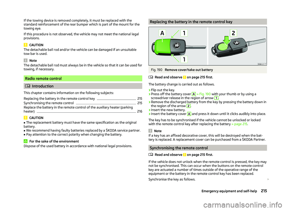
The battery change is carried out as follows.
›
Flip out the key.
›
Press off the battery cover
A
» Fig. 190 with your thumb or by using a
screwdriver release in the region of arrow
1
.
›
Remove the discharged battery from the key by pressing the battery down in
the region of the arrow
2
.
›
Insert the new battery.
›
Insert the battery cover
A
and press it down until it clicks audibly into place.
The key has to be synchronised if the vehicle cannot be unlocked or locked
with the remote control key after replacing the battery » page 215.
Note
If a key has an affixed decorative cover, this will be destroyed when the bat-
tery is replaced. A replacement cover can be purchased from a ŠKODA Partner.
Synchronising the remote control
Read and observe
on page 215 first.
If the vehicle does not unlock when the remote control is pressed, the key maynot be synchronised. This can occur when the buttons on the remote control
key are actuated a number of times outside of the operative range of the
equipment or the battery in the remote control key has been replaced.
Synchronise the key as follows.
215Emergency equipment and self-help
Page 227 of 252
Replacing the bulb for the licence plate light226Rear light (Superb Combi)226
Replacing bulbs in rear light (Superb Combi)
227
Some manual skills are required to change a bulb. For this reason, we recom-
mend having bulbs replaced by a specialist garage or seeking other expert help
in the event of any uncertainties.
› Switch off the ignition and all of the lights before replacing a bulb.
› Faulty bulbs must only be replaced with the same type of bulbs. The designa-
tion is located on the light socket or the glass bulb.
› A stowage compartment for replacement bulbs is located in a plastic box in
the spare wheel or underneath the floor covering in the boot.
WARNING■ Always read and observe the warnings before completing any work in the
engine compartment » page 186.■
Accidents can be caused if the road in front of the vehicle is not suffi-
ciently illuminated and the vehicle cannot or can only be seen with difficul-
ty by other road users.
■
Bulbs H7 H8 and H15 are pressurised and may burst when changing the
bulb - risk of injury! We therefore recommended wearing gloves and safety
glasses when changing a bulb.
■
Gas discharge bulbs (xenon bulbs) operate with a high voltage, professio-
nal knowledge is required – risk of death!
■
Switch off the respective vehicle light when changing the bulb.
CAUTION
Do not take hold of the glass bulb with naked fingers (even the smallest
amount of dirt reduces the working life of the light bulb). Use a clean cloth,
napkin, or similar.
Note
■ This Owner's Manual only describes the replacement of bulbs where it is pos-
sible to replace the bulbs on your own without any complications arising. Other
bulbs must be replaced by a specialist garage.■
We recommend that a box of replacement bulbs always be carried in the ve-
hicle. Replacement bulbs can be purchased from ŠKODAOriginal Accessories.
■
We recommend having the headlight settings checked by a specialist garage
after replacing a bulb in the main beam, low beam or fog lights.
■
In case of failure of a xenon gas discharge lamp or an LED diode, visit a spe-
cialist garage.
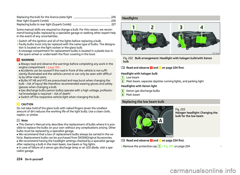
HeadlightsFig. 202
Bulb arrangement: Headlight with halogen bulb/with Xenon
bulb
Read and observe
and on page 224 first.
Headlight with halogen bulb Low beam
Main beam, separate daytime running lights, and parking light
Headlights with Xenon light Xenon gas discharge bulbs
Main beam
Replacing the low beam bulb
Fig. 203
Halogen headlight: Changing the
bulb for the low beam
Read and observe and on page 224 first.
›
Remove the protective cap
1
» Fig. 202 on page 224 .
1234224Do-it-yourself
Page 228 of 252
›Turn the plug with the bulb A
» Fig. 203 as far as the stop in the direction of
the arrow.›
Change the bulb.
›
Insert the bulb holder with the new bulb and turn in an anti-clockwise direc-
tion as far as the stop.
›
Fit the protective cover
1
.
Replacing bulb for main beam and daytime running lights
Fig. 204
Halogen headlight: Replacing
the bulb for main beam and sep-
arate daytime running lights
Read and observe and on page 224 first.
›
Remove the protective cap
2
» Fig. 202 on page 224 .
›
Turn the bulb holder
A
» Fig. 204 in the direction of the arrow as far as the
stop.
›
Replace the bulb, insert the bulb holder with the new bulb and turn in the
opposite direction to that of the arrow as far as it goes.
›
Fit the protective cover
2
.
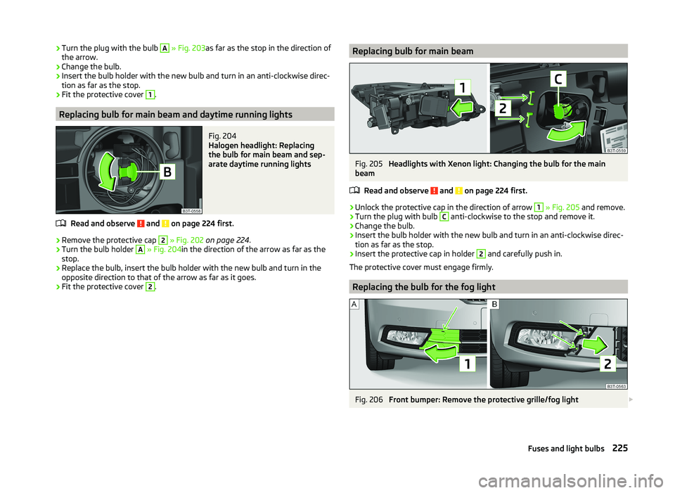
Replacing bulb for main beamFig. 205
Headlights with Xenon light: Changing the bulb for the main
beam
Read and observe
and on page 224 first.
›
Unlock the protective cap in the direction of arrow
1
» Fig. 205 and remove.
›
Turn the plug with bulb
C
anti-clockwise to the stop and remove it.
›
Change the bulb.
›
Insert the bulb holder with the new bulb and turn in an anti-clockwise direc-
tion as far as the stop.
›
Insert the protective cap in holder
2
and carefully push in.
The protective cover must engage firmly.
Replacing the bulb for the fog light
Fig. 206
Front bumper: Remove the protective grille/fog light
225Fuses and light bulbs
Page 241 of 252

Convenience operationsliding / tilting roof65
sliding / tilting roof (Superb Estate)67
Convenience turn signal70
Coolant191
Checking192
Messages36
Replenishing192
Temperature gauge31
Warning light36
CORNER See Fog lights with CORNER function
71
Correct seated position9
Driver9
Front passenger10
Instructions11
Rear seats11
Counter for distance driven32
Cruise control system Activating/deactivating
161
Changing the stored speed162
Storing and maintaining speed162
Switching off temporarily162
Warning light41
Cruise Control System161
Cup holders90
D
DAY LIGHT see Daylight running lights
69
Daylight running lights69
De-icing the windscreen and rear window75
Deactivating an airbag21
Decorative films179
Delayed locking of the boot lid see boot lid
58
Diesel refer to Fuel
185
diesel - particulate filter39
Diesel fuel Operation in winter
185
Diesel particulate filter warning light
39
Digital Clock Time
32
Dipstick190
Display31
Compass points48
Coolant temperature31
Fuel supply32
Gear changes43
Service intervals48
Display a low temperature43
Display of the second speed33
Distance driven32
Door Child safety lock
55
Closing52
Emergency locking217
Emergency locking the driver's door216
Opening52
Warning light for open door36
Door open Warning light
36
Driver Steering Recommendation (DSR)155
Driving Abroad
153
Driving through water on streets152
Emissions229
Fuel consumption229
Driving economically Economical gear changing
149
Driving through water152
DSR155
DVD-preinstallation136
E
Economical and environmentally friendly driv- ing
149
Economical driving Ballast
151
Driving at full throttle150
Idling150
Looking ahead149
Regular maintenance151
Saving energy151
Short distances150
Tyre pressure150
EDL Operation
155
Electrical power windows63
Button in the driver's door61, 62
Button in the rear doors63
Operational faults64
Electric boot lid Force limit
59
Manual operation59
Electric luggage compartment lid Acoustic signals
61
Adjusting the top lid position61
Deleting the top lid position61
Malfunctions61
Operating59
Electric sliding/tilting roof64
Electronic Differential Lock (EDL)155
Electronic immobilizer139
Electronic Stability Control (ESC)154
Emergency Activation of the sliding/tilting roof
218
Changing a wheel205
Hazard warning light system72
jump-starting211
Jump-starting211
Locking the door without a locking cylinder217
Locking the driver's door216
238Index