turn signal SKODA SUPERB 2010 2.G / (B6/3T) User Guide
[x] Cancel search | Manufacturer: SKODA, Model Year: 2010, Model line: SUPERB, Model: SKODA SUPERB 2010 2.G / (B6/3T)Pages: 287, PDF Size: 16.59 MB
Page 65 of 287
Lights and Visibility
64
Mode motorway
In the mode “motorway” the dispersion of the co ne of light is so widespread, that it illu-
minates also the left (and right)
7) lane of the motorway, so that the driver can react in
time to an obstacle or any other danger. The mode is activated stepwise as of a speed
of 90 km/h. It gains its greatest effectiveness at speeds above 120 km/h.
Tourist light
This mode makes it possible to drive in countries with opposing traffic system, driving
on the left/right, without dazzling the oncoming vehicles. When the mode “tourist
light” is active, the above mentioned modes and the side to side swivel of the headlight
is deactivated.
The mode “tourist light” is activated / deac tivated via the information display* in the
menu:
SETUP
Tr a v e l m o d e
Off
On
Cornering lights
The cornering lights are used to illuminate the curves by means of the cone of light
swiveling together with the front headlight with Xenon lights*. This function is active
when the speed of the car increases to more than 10km/h.
The swiveling function of the headlights ca n be switched off / on via the menu point
Assistants in the main menu of the information display* page 23.WARNING
If the cornering ligh ts are defective, the headlights are automatically lowered to
the emergency position, whic h prevents a possible dazzling of oncoming traffic.
Thus the illuminated length of the road is shortened. Drive carefully and have
the car inspected immediatel y by a specialist garage.
Note
The AHL system* complements the functions of the fog lights with the function
“CORNER” page 64 and the function of the dy namic headlamp beam adjustment*.
The System AHL* is solely delivered with Bi-Xenon gas discharge bulbs for low
beam and main beam lights.
Fog lights
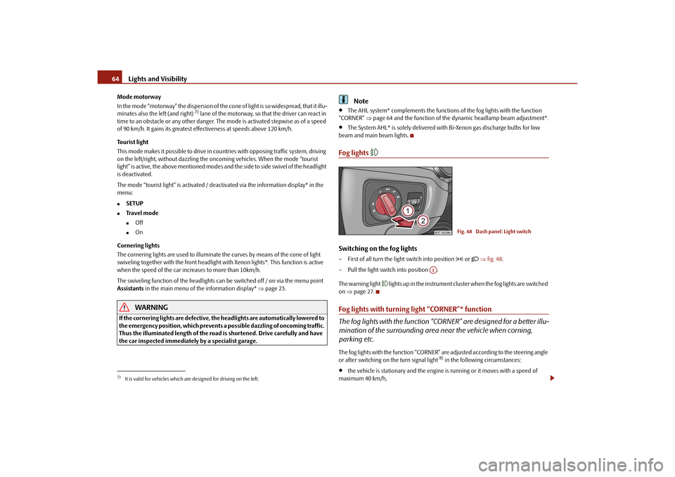
Switching on the fog lights– First of all turn the light switch into position
or fig. 48 .
– Pull the light switch into position .
The warning light
lights up in the instrument cluste r when the fog lights are switched
on page 27.
Fog lights with turning light “CORNER”* function
The fog lights with the function “CORNER” are designed for a better illu-
mination of the surrounding area near the vehicle when corning,
parking etc.The fog lights with the function “CORNER” ar e adjusted according to the steering angle
or after switching on the turn signal light
8) in the following circumstances:
the vehicle is stationary and the engine is running or it moves with a speed of
maximum 40 km/h,
7)It is valid for vehicles which are designed for driving on the left.
Fig. 48 Dash panel: Light switch
A1
s3fg.2.book Page 64 Friday, April 30, 2010 12:17 PM
Page 66 of 287
Lights and Visibility65
Using the system
Safety
Driving Tips
General Maintenance
Breakdown assistance
Technical Data
the daylight driving lights are not switched on,
the low beam is switched on or th e light switch is in the position
and the
intensity of the ambient light causes the low beam to be switched on,
the fog lights are not switched on,
no reverse gear is engaged.Note
If you engage the reverse gear during the active function “CORNER”, both fog lights
illuminate.Rear fog light
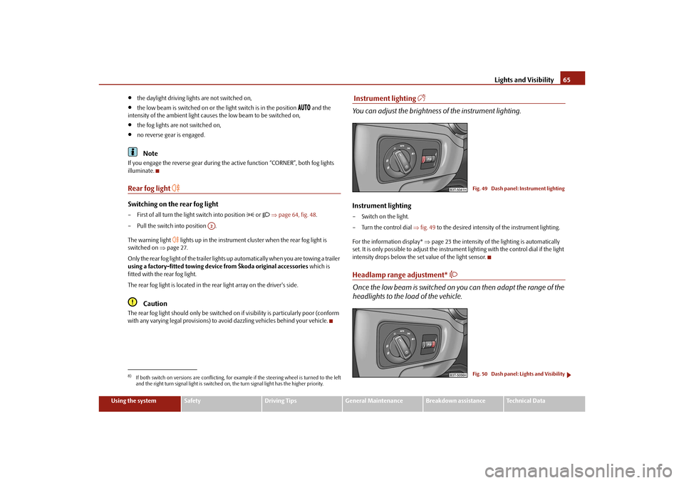
Switching on the rear fog light– First of all turn the light switch into position
or page 64, fig. 48 .
– Pull the switch into position .
The warning light
lights up in the instrument cluster when the rear fog light is
switched on page 27.
Only the rear fog light of the trailer lights up automatically when you are towing a trailer
using a factory-fitted towing device from Škoda original accessories which is
fitted with the rear fog light.
The rear fog light is located in the rear light array on the driver's side.
Caution
The rear fog light should only be switched on if visibility is particularly poor (conform
with any varying legal provisions) to avoi d dazzling vehicles behind your vehicle.
Instrument lighting
You can adjust the brightness of the instrument lighting.Instrument lighting– Switch on the light.
– Turn the control dial fig. 49 to the desired intensity of the instrument lighting.
For the information display* page 23 the intensity of the lighting is automatically
set. It is only possible to adjust the instrume nt lighting with the control dial if the light
intensity drops below the set value of the light sensor.Headlamp range adjustment*
Once the low beam is switched on you can then adapt the range of the
headlights to the load of the vehicle.
8)If both switch on versions are conflicting, for ex ample if the steering wheel is turned to the left
and the right turn signal light is switched on, the turn signal light has the higher priority.
A2
Fig. 49 Dash panel: Instrument lightingFig. 50 Dash panel: Lights and Visibility
s3fg.2.book Page 65 Friday, April 30, 2010 12:17 PM
Page 67 of 287
Lights and Visibility
66
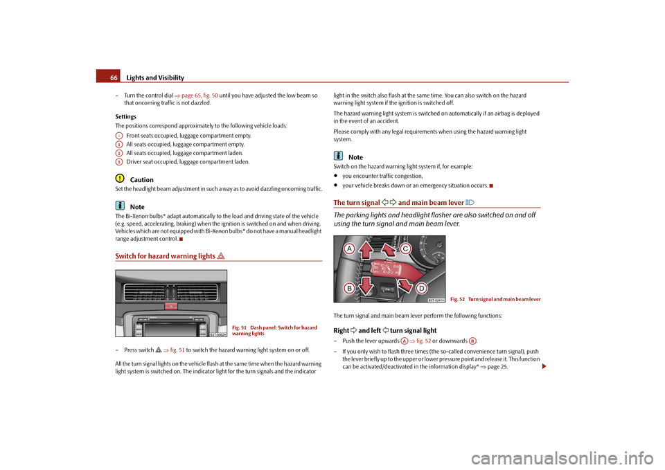
– Turn the control dial page 65, fig. 50 until you have adjusted the low beam so
that oncoming traffic is not dazzled.
Settings
The positions correspond approximately to the following vehicle loads:
Front seats occupied, luggage compartment empty.
All seats occupied, luggage compartment empty.
All seats occupied, luggage compartment laden.
Driver seat occupied, lu ggage compartment laden.
Caution
Set the headlight beam adjustment in such a way as to avoid dazzling oncoming traffic.
Note
The Bi-Xenon bulbs* adapt automatically to the load and driving state of the vehicle
(e.g. speed, accelerating, braking) when the ig nition is switched on and when driving.
Vehicles which are not equipped with Bi-Xenon bulbs* do not have a manual headlight
range adjustment control.Switch for hazard warning lights
– Press switch
fig. 51 to switch the hazard warning light system on or off.
All the turn signal lights on the vehicle flas h at the same time when the hazard warning
light system is switched on. The indicator light for the turn signals and the indicator light in the switch also flash at the same time. You can also switch on the hazard
warning light system if the ignition is switched off.
The hazard warning light system is switched
on automatically if an airbag is deployed
in the event of an accident.
Please comply with any legal requirements when using the hazard warning light
system.
Note
Switch on the hazard warning light system if, for example:
you encounter traffic congestion,
your vehicle breaks down or an emergency situation occurs.
The turn signal
and main beam lever
The parking lights and headlight flasher are also switched on and off
using the turn signal and main beam lever.The turn signal and main beam le ver perform the following functions:Right
and left
turn signal light
– Push the lever upwards fig. 52 or downwards .
– If you only wish to flash three times (the so-called convenience turn signal), push
the lever briefly up to the upper or lower pr essure point and release it. This function
can be activated/deactivated in the information display* page 25.
A-A1A2A3
Fig. 51 Dash panel: Switch for hazard
warning lights
Fig. 52 Turn signal and main beam lever
AA
AB
s3fg.2.book Page 66 Friday, April 30, 2010 12:17 PM
Page 68 of 287
Lights and Visibility67
Using the system
Safety
Driving Tips
General Maintenance
Breakdown assistance
Technical Data
– Turn signal for changing lanes - in order to
only flash briefly, move the lever up or
down to the pressure point and hold it in this position.
Main beam
– Switch on the low beam.
– Push the lever forwards in direction of arrow (spring-tensioned position).
– If you push the lever towards the steering wheel in direction of arrow (spring-
tensioned position) the main beam is switched off.Headlight flasher
– Pull the lever towards the steering wheel (spring-tensioned position) in direction
of arrow - the main beam and warning light
in the instrument cluster come
on.
Parking light
– Switch off the ignition.
– Push the lever up or down - the right-hand or left-hand parking light is switched
on.
Information concerning the function of the lights.
The turn signal system only operates when the igniti on is switched on. The corre-
sponding warning light
or in the instrument cluster also flashes.
The turn signal is automatically cancelled after negotiating a curve.
The indicator light flashes at twice its normal rate if a bulb of the turn signal light
fails.
The side light and rear light on the appropriate side of the vehicle are switched on
when the parking light is selected. The parking light only operates if the ignition is
switched off.Caution
Use main beam or the headlight flasher only if this does not risk dazzling other road
users.
Note
If you have switched on the right or left turn signal light and you switch off the igni-
tion, the parking light is not automatically switched on.
Use only in accordance with the legal requirements the described lighting and
signal systems.
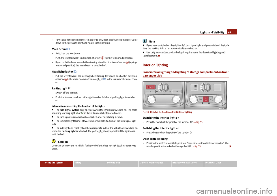
Interior lightingFront interior lighting and lighting of storage compartment on front passenger sideFig. 53 Detail of the headliner: front interior lightingSwitching the interior light on– Press the switch at the point of the symbol
fig. 53 .
Switching the interior light off– Press the switch at the point of the symbol O.Door contact setting– Position the switch into middle position. On vehicles without interior monitor*, the
middle position is marked with a symbol
fig. 53 .
AC
AD
AD
s3fg.2.book Page 67 Friday, April 30, 2010 12:17 PM
Page 83 of 287
Seats and Stowage
82
The seat backrests must not be angled too far back when driving otherwise
this will affect proper operation of the se at belts and of the airbag system - risk
of injury!Note
If the movement of the seat is inadvertently interrupted during an adjustment, once
again press the switch in the appropriate di rection and continue with the adjustment
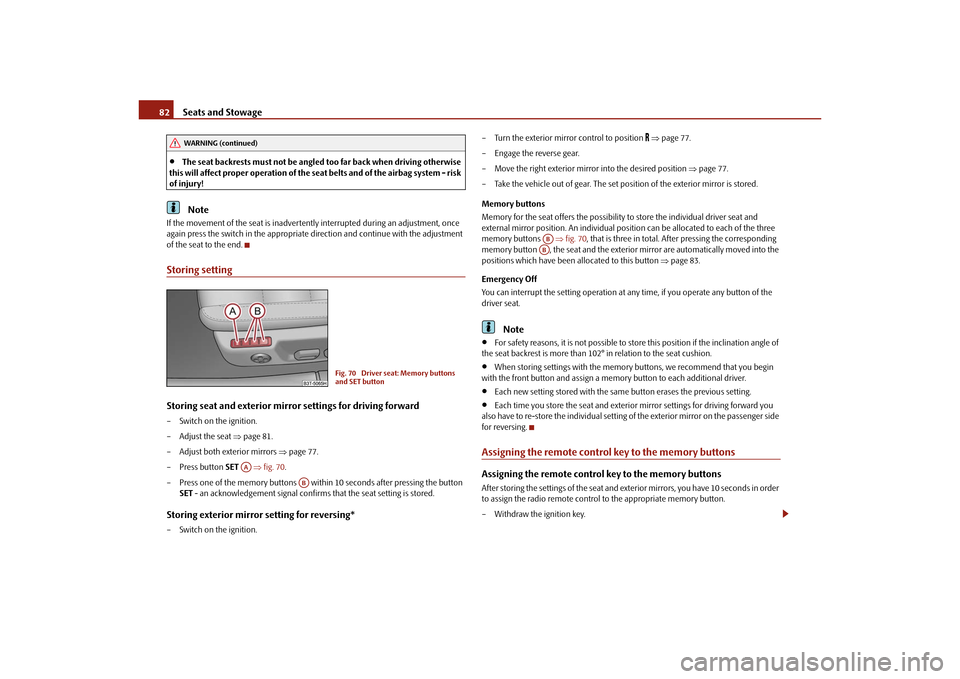
of the seat to the end.Storing settingStoring seat and exterior mirror settings for driving forward– Switch on the ignition.
– Adjust the seat page 81.
– Adjust both exterior mirrors page 77.
– Press button SET fig. 70 .
– Press one of the memory buttons within 10 seconds after pressing the button SET - an acknowledgement signal confirms that the seat setting is stored.Storing exterior mirror setting for reversing*– Switch on the ignition. – Turn the exterior mirror control to position
page 77.
– Engage the reverse gear.
– Move the right exterior mirror into the desired position page 77.
– Take the vehicle out of gear. The set position of the exterior mirror is stored.
Memory buttons
Memory for the seat offers the possibility to store the individual driver seat and
external mirror position. An individual posi tion can be allocated to each of the three
memory buttons fig. 70 , that is three in total. Af ter pressing the corresponding
memory button , the seat and the exterior mirror are automatically moved into the
positions which have been allocated to this button page 83.
Emergency Off
You can interrupt the setting operation at any time, if you operate any button of the
driver seat.
Note
For safety reasons, it is not possible to store this position if the inclination angle of
the seat backrest is more than 102 ° in relation to the seat cushion.
When storing settings with the memory buttons, we recommend that you begin
with the front button and assign a memory button to each additional driver.
Each new setting stored with the same button erases the previous setting.
Each time you store the seat and exterior mirror settings for driving forward you
also have to re-store the individual setting of the exterior mirror on the passenger side
for reversing.
Assigning the remote contro l key to the memory buttonsAssigning the remote control key to the memory buttonsAfter storing the settings of the seat and exterior mirrors, you have 10 seconds in order
to assign the radio remote control to the appropriate memory button.
– Withdraw the ignition key.
WARNING (continued)
Fig. 70 Driver seat: Memory buttons
and SET button
AA
AB
ABAB
s3fg.2.book Page 82 Friday, April 30, 2010 12:17 PM
Page 84 of 287
Seats and Stowage83
Using the system
Safety
Driving Tips
General Maintenance
Breakdown assistance
Technical Data
– Press the unlock button
page 49, after the successful assignment an audible
signal will sound. The setting is stored with the memory button which you have
selected.
Assigning the remote control key to the memory buttons on the KESSY*
systemOn vehicles which are equipped with the KESSY* system, the following procedure for
assigning the remote control key to the memory buttons exists for electrically adjust-
able front seats and mirrors*.
– Switch the ignition off within 10 seconds after storing the setting.
– Open the driver door.
– Press the unlock button on the remo te control key within 10 seconds.
If you wish to be able to retrieve the settings which are stored in the memory by also
using the radio remote control, you have to assign the radio remote control to a
memory button in each case.
If you wish, you can obtain an additional remote control key from an authorised Škoda
Service partner and then assign the remote control key to another memory button.
Note
If the radio remote control had previously been assigned to another memory
button, this setting is then erased by the new assignment.
If you assign the radio remote control to a memory button which has already been
assigned to a radio remote control, the ol d assignment is also replaced by a new
assignment in this case.
The assignment of the radio remote co ntrol to a memory button is retained,
however, after reassigning the seats and exterior mirrors.
After the successful assignment, the turn si gnal lights flash and an audible signal
will sound as a confirmation. The setting is stored with the memory button which you
have selected.
Retrieving settings of the seat and mirrors
You can retrieve the stored settings either with the memory buttons or
with the remote control*.Retrieving settings with memory buttons– In order to retrieve the stored setting, you have two possibilities:
– One-touch automatic memory: briefly press the desired memory button
page 82, fig. 70 . The seat and exterior mirror are moved automatically into the
stored positions (this applies only if the ignition is switched on and the speed is less
than 5 km/h).
– Memory keying : Press and hold the desired memory button pressed long
enough until the seat and the exterior mi rror are moved into the stored positions.Retrieving settings with remote control– If the driver door is closed and the ignition is switched off, briefly press the unlock
button of the radio remote control page 49 and then open the driver door.
– The seat and exterior mirrors now move automatically into the stored positions.Retrieving setting of exterior mirror for reversing*– Turn the rotary knob for the exterior mirror setting into the position
page 77
before engaging the reverse gear.
The mirror returns into its initial position, after the rotary knob is moved out of the
position
and put into another position or if the speed is more than 15 km/h.
Emergency Off
You can interrupt the setting operation at any time, if you operate any button of the
driver seat.
AB
AB
s3fg.2.book Page 83 Friday, April 30, 2010 12:17 PM
Page 120 of 287

Air conditioning system119
Using the system
Safety
Driving Tips
General Maintenance
Breakdown assistance
Technical Data
The prerequisite for the correct switching on of the auxiliary heating (auxiliary heating
and ventilation) according to the programmed
pre-set time is the correct setting of the
current time and the weekday page 118.
If the system is running, a wa rning light in the button for direct switching on/off of the
auxiliary heating lights up.
The running system deactivate s after expiration of the operating period or is deacti-
vated earlier by pressing the button for dire ct switching on/off of the auxiliary heating
page 118.
A random pre-set time can be deactivated by selecting the menu point Deactivate in
the menu Activate.
After selecting the menu Fa c t o r y s e t t i n g in the menu Aux. heating , it is possible to
return to the factory setting.
Radio remote control
The auxiliary heating (auxiliary heating and ventilation) can be
switched on or off with the remote control.– For switching on, press the button .
– For switching off, press the button .
The transmitter and the battery are housed in the housing of the remote control. The
receiver is located in the interior of the car.
If the battery is properly charged, the effective range is up to 600 m. For switching on
or off the auxiliary heating, hold the remo te control vertically with the antenna
fig. 124 towards the top. You must not cover over the antenna with the fingers or the
palm of the hand. Obstacles between the ra dio remote control and the vehicle, bad
weather conditions and a weaker batt ery can clearly reduce the range.
The auxiliary heating can only be switched on or off with the radio remote control, if
the distance between the radio remote control and the vehicle is at least 2 m.
Warning light in the radio remote control
The warning light in the radio remote control fig. 124 indicates after a keystroke if
the remote control signal was received by the auxiliary heating and if the battery is
adequately charged.
Caution
There are electronic components in the radio remote control, protect the remote
control against water, severe shocks and direct sun rays.
Fig. 124 Auxiliary heating: Radio
remote control
ONOFF
AA
Display warning light
Importance
Lights up green for 2 seconds.
The auxiliary heating was switched on.
Lights up red for 2 seconds.
The auxiliary heating was switched off.
Slowly flashes green for 2 seconds.
The ignition signal was not received.
Quickly flashes green for 2 seconds.
The auxiliary heating is blocked, e. g
because the tank is nearly empty or there
is a fault in the auxiliary heating.
Flashes red for 2 seconds.
The switch off signal was not received.
Lights up orange for 2 seconds, then
green or red.
The battery is weak, however the switch-
ing on or off signal was received.
Lights up orange for 2 seconds, then
flashes green or red.
The battery is weak, however the switch-
ing on or off signal was not received.
Flashes orange for 5 seconds.
The battery is discharged, however the
switching on or off signal was not
received.
s3fg.2.book Page 119 Friday, April 30, 2010 12:17 PM
Page 129 of 287

Starting-off and Driving
128
Move selector lever to position P/N! or P/N
10)
This message is shown if the selector lever is not in the position P or N, when locking
the steering, switching the ignition on/off or when starting the engine.
Move selector lever to position P! or P
10)
This message is shown if the selector lever is not in the position P when opening the
driver door and the ignition is switched off, or if it is not in the position P, when
switching off the ignition while the driver door is open. The message disappears after
a few seconds by switching on the ignition or by moving the selector lever into the
position P.Parking aid*Rear parking aid*
The parking aid provides a warning of obstacles behind the vehicle.The audible parking aid determines the distance between the rear bumper and an
obstacle located behind the ve hicle with the aid of ultrasound sensors. The tones of
the parking aid can be adapted in the menu of the information display* page 25.
The sensors are integrated in the rear bumper. Range of sensors
The clearance warning begins at a distance of about 160 cm from the obstacle (area
fig. 131 ). The interval between the warning signals becomes shorter as the clear-
ance is reduced.
A continuous tone sounds from a distance of approx. 30 cm (area ) - danger area.
You should not reverse any further after this signal sounds! If the vehicle is
equipped with a factory-fitted towing device*, the border of the danger area starts -
continuous tone - 5 cm further behind th e vehicle. The vehicle can be extended
through an installed detachable towing device.
On vehicles equipped with a factory-fitted radio* or navigation system*, the distance
to the obstruction is shown graphically in the display. On vehicles with a factory-fitted
towing device, the sensors are deactivated when towing a trailer. The driver is informed
about this by a graphic display (vehicle towing a trailer) in the radio* or the navigation*
display. The factory-fitted radio* or navigati on system* can be set so that the play func-
tion volume decreases when activating the parking aid, see Owner's Manual radio* or
navigation system*. This improves the audibility of the parking aid.
Activating
The parking aid is activated automatically when reverse gear is engaged and the igni-
tion is turned on. This is confirmed by a brief acknowledgement signal.
Deactivating
The parking aid is deactivated by removing the reverse gear.
WARNING
The parking aid is not a substitute for the driver paying proper attention and
it is always the driver's responsibility to take care when parking the vehicle or
carrying out similar manoeuvres.
You should therefore satisfy yourself, before reversing, that there is no small
obstacle, such as a rock, thin post, trai ler drawbar etc., behind your vehicle.
Such an obstacle might not be within the range detected by the sensors.
Under certain circumstances, surfaces of certain objects and types of
clothing cannot reflect the signal of the parking aid. Thus, these objects or
people who wear such clothing are not recognised by the sensors of the parking
aid.
10)Valid for vehicles with automatic gearbox.
Fig. 131 Parking aid: Detection range of
rear sensors
AA
AB
s3fg.2.book Page 128 Friday, April 30, 2010 12:17 PM
Page 130 of 287

Starting-off and Driving129
Using the system
Safety
Driving Tips
General Maintenance
Breakdown assistance
Technical Data
Note
The parking aid does not operate if you are towing a trailer (applies to models
which feature a factory-fitted towing device*).
If a warning signal sounds for about 3 seconds after switching the ignition on and
engaging reverse gear, and there is no obstac le close to your vehicle, this indicates a
system fault. Have the fault rectified by a specialist workshop.
The sensors must be kept clean and free of ice to enable the parking aid to operate
properly.
Front and rear parking aid*
The parking aid provides a warning of obstacles in front and behind the
vehicle.Fig. 132 Activating the parkin g aid / parking aid: Detection range of the front sensorsThe audible parking aid determines the distance between the front or rear bumper and
an obstacle with the aid of ultrasound sens ors. The sensors are integrated in the front
and rear bumper. The signal tones for the fr ont parking aid sound higher as standard
than for the rear parking aid. The tones of the parking aid can be adapted in the menu
of the information display* page 25.
Range of sensors
The distance warning begins at a distance of about 120 cm from the obstacle in front
of the vehicle (area fig. 132 ) and about 160 cm from the obstacle behind the
vehicle (area fig. 132). The interval between the warning signals becomes
shorter as the clearance is reduced. A continuous tone sounds from
a distance of approx. 30 cm (area ) - danger area.
From this moment on do not continue driving! If the vehicle is equipped with a
factory-fitted towing device*, the border of the danger area starts - continuous tone -
5 cm further behind the vehicle. The vehi cle can be extended through an installed
detachable towing device.
On vehicles equipped with a factory-fitted radio* or navigation system*, the distance
to the obstruction is shown graphically in the display. On vehicles with a factory-fitted
towing device, the rear sensors are deactivated when towing a trailer. The driver is
informed about this by a graphic display (vehic le towing a trailer) in the radio* or the
navigation* display. The factory-fitted radio* or navigation system* can be set so that
the play function volume decreases when activating the parking aid, see Owner's
Manual radio* or navigation system*. This improves the audibility of the parking aid.
Activating
The parking aid is activated when the reverse gear is engaged and the ignition is
turned on or by pressing the button fig. 132 - the symbol
lights up in the button.
The activation is confirmed by a brief acknowledgement signal.
Deactivating
The parking aid is deactivated after pressing the button°
fig. 132 or at a speed of
more than 10 km/h - the symbol
in the button is no longer illuminated.
WARNING
The parking aid is not a substitute for the driver paying proper attention and
it is always the driver's re sponsibility to take care when reversing the vehicle or
carrying out similar manoeuvres.
You should therefore satisfy yourself, before reversing, that there is no small
obstacle, such as a rock, thin post, trailer drawbar etc., in front or behind your
vehicle. Such an obstacle might not be within the range detected by the sensors.
Under certain circumstances, surfaces of certain objects and types of
clothing cannot reflect the signal of the parking aid. Thus, these objects or
people who wear such clothing are not recognised by the sensors of the parking
aid.
AA
AA
AB
s3fg.2.book Page 129 Friday, April 30, 2010 12:17 PM
Page 132 of 287

Starting-off and Driving131
Using the system
Safety
Driving Tips
General Maintenance
Breakdown assistance
Technical Data
In order to avoid damaging th e sensors while cleaning with high-pressure cleaners
or steam jets, the sensors must only be directly sprayed for short periods while a
minimum distance of 10 cm must be observed.Note
A component of the park assist is the front and rear parking aid*.
The electronic stability programme (ESP) must always be switched on for the
parking procedure.
Only the front parking aid operates if yo u are towing a trailer (applies only to
models which feature a factory-fitted towing device*). This is why it is not possible to
park backwards with the help of the park assist when towing a trailer.
The sensors must be kept clean and free of ice to enable the parking aid to operate
properly.
Switch on display of the park as sist in the information display*Fig. 133 Switch on display of the park assist in the information display / information display:
Finding a suitable parking spaceSwitch on display of the park assist in the information display*– Press the button fig. 133 .
– Drive past the parking row up to maximum 30 km/h and with a distance of 0.5 m to 1.5 m fig. 133. Operate the turn signal for the driver's side if you wish to park on this side of the road.
In the information display* the search area
for the parking space is indicated on the
driver's side.
If the button is pressed above a speed of 30 km/h, the display appears in the display of
the instrument cluster as soon as you drive slower than 30 km/h.
Note
If the park assist is switched on, a yello w warning light lights up in the button.
The search for suitable parking spaces is automatic after switching on the ignition
at speeds of more than 30 km/h. Searchin g for a parking space is performed at the
same time on the driver and front passenger side.
If the sensors find a suitable parking space, they store its parameters until another
suitable parking space has been found or until a distance of 10 m had been driven after
finding the parking space. This is why it is possible to switch on the park assist after
driving past the parking space, the information on whether this parking space is suit-
able for parking appears in the information display*.
Parking with the help of the park assist and concluding the parking procedureFig. 134 Information display: the determined pa rking space with the information to drive on
and for engaging the reverse gear AA
AB
s3fg.2.book Page 131 Friday, April 30, 2010 12:17 PM