turn signal SKODA SUPERB 2010 2.G / (B6/3T) Owner's Guide
[x] Cancel search | Manufacturer: SKODA, Model Year: 2010, Model line: SUPERB, Model: SKODA SUPERB 2010 2.G / (B6/3T)Pages: 287, PDF Size: 16.59 MB
Page 133 of 287

Starting-off and Driving
132
Fig. 135 Information display: Information for engaging the forward gear or the reverse
gear The time limit for the parking procedure with the help of the park assist lasts 180
seconds.
– If the park assist has recognised a suitable parking space, it is shown in the infor-
mation display* page 131, fig. 134 .
– Drive on further until the display page 131, fig. 134 appears.
– Bring the vehicle to a stop for at least 1 second.
– Engage the reverse gear or move the selector lever* into the position R.
– As soon as the following message is shown in the information display*: Steering
interv. active. Monitor area around veh.! , let go of the steering wheel, the
steering will be taken over by the system.
– Pay attention to the immediate area arou nd the vehicle and drive backwards with
a speed of max. 7 km/h, at the same time operate the pedal.
– In the event that the parking procedure cannot be carried out in one go, proceed to parking in further stages. If the forward arrow fig. 135 flashes in the infor-
mation display*, engage the 1st gear or mo ve the selector lever* into the position
D .
– Please wait until the steering wheel turn s automatically into the required position
and then carefully drive a little forward at a speed of max. 7 km/h, at the same time
operate the pedal.
– If the backward arrow flashes fig. 135 in the information display*, once again
engage the reverse gear or move the selector lever* into the position R. – Please wait until the steering wheel turns automatically into the required position
and then carefully drive backwards. Yo u can repeat these steps several times.
– End the parking procedure from a distance on the basis of the information of the
system.
As soon as the parking procedure is completed, an audible signal sounds and in the
information display* the following message appears: Steering intervention finished!
Please take over steering! .
Switch off park assist
The park assist switches off during one of the following occurences:
A speed of 30 km/h exceeded
A speed of 7 km/h exceeded during the parking procedure
A time limit of 180 seconds exceeded for the parking procedure
The button pressed for the park assist
Parking aid activated
Switch off TCS system
Intervention of the driver in the automatic steering procedure (stop the steering
wheel)
disengage the reverse gear or take the selector lever* out of the position R when
driving backwards into the parking space.
Further warning and information texts of the park assist in the information
display*:
Park Assist finished.
The parking procedure has ended or after switching on the ignition, the vehicle has not
been driven above 10 km/h.
Park Assist: Speed too high!
Reduce the speed below 30 km/h.
Driver steering intervention: Please take over steering!
The parking procedure is ended through driver intervention.
AC
AD
AB
AC
AD
s3fg.2.book Page 132 Friday, April 30, 2010 12:17 PM
Page 150 of 287
Communication149
Using the system
Safety
Driving Tips
General Maintenance
Breakdown assistance
Technical Data
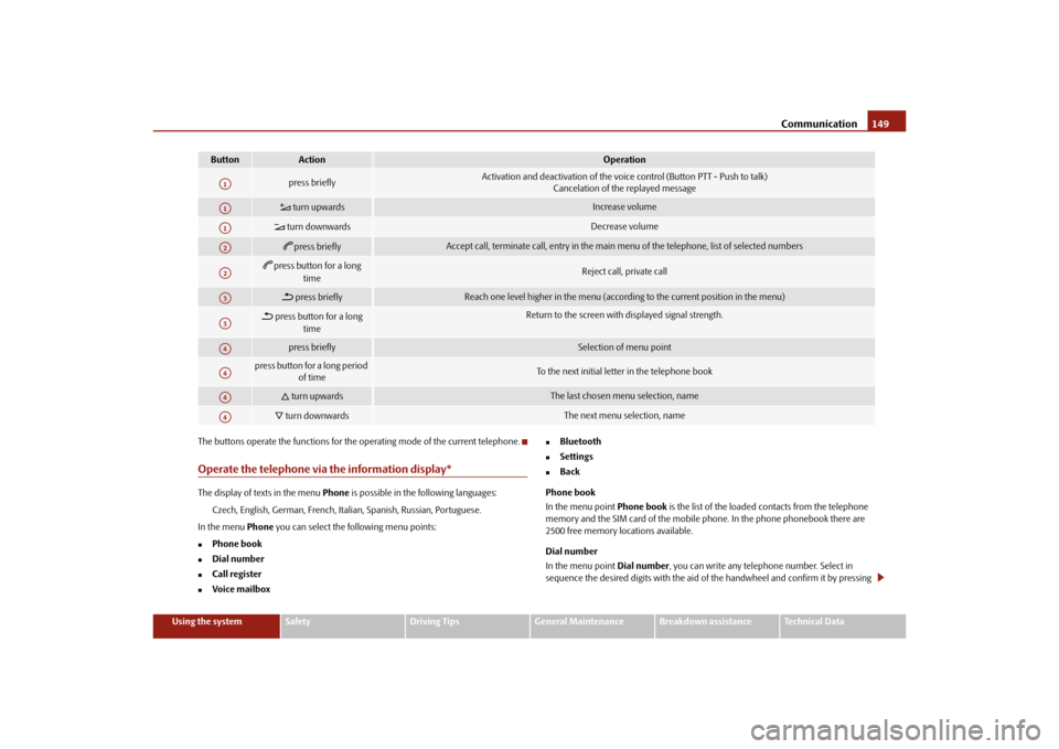
The buttons operate the functions for the operating mode of the current telephone.
Operate the telephone via the information display*The display of texts in the menu
Phone is possible in the following languages:
Czech, English, German, French, Italia n, Spanish, Russian, Portuguese.
In the menu Phone you can select the following menu points:
Phone book
Dial number
Call register
Voice mailbox
Bluetooth
Settings
Back
Phone book
In the menu point Phone book is the list of the loaded contacts from the telephone
memory and the SIM card of the mobile phone. In the phone phonebook there are
2500 free memory locations available.
Dial number
In the menu point Dial number, you can write any telephone number. Select in
sequence the desired digits with the aid of the handwheel and confirm it by pressing
Button
Action
Operation
press briefly
Activation and deactivation of the voice control (Button PTT - Push to talk) Cancelation of the replayed message
turn upwards
Increase volume
turn downwards
Decrease volume
press briefly
Accept call, terminate call, entry in the main menu of the telephone, list of selected numbers
press button for a long
time
Reject call, private call
press briefly
Reach one level higher in the menu (accordi ng to the current position in the menu)
press button for a long
time
Return to the screen with displayed signal strength.
press briefly
Selection of menu point
press button for a long period of time
To the next initial letter in the telephone book
turn upwards
The last chosen menu selection, name
turn downwards
The next menu selection, name
A1A1A1A2A2A3A3A4A4A4A4
s3fg.2.book Page 149 Friday, April 30, 2010 12:17 PM
Page 163 of 287
Passive Safety
162
Ensure that the lighting and the turn signal system are functioning properly.
Inspect the tyre inflation pressure.
Ensure that all the windows offer a good visibility to the outside.
Safely attach the items of luggage page 87, “Loading the luggage compartment”.
Ensure that no objects can obstruct the pedal.
Adjust the mirror, the front seat and the head restraint to match your body size.
Point out to your occupants that the head restraints must be adjusted to match
their body size.
Protect the children in suitable child seats with correctly fastened seat belts
page 180, “Transporting children safely”.
Adopt the correct seated position page 162, “Correct seated position”. Also
inform your occupants to adopt the correct seated position.
Fasten the seat belt correctly. Also inform your occupants to properly fasten the
seat belts page 167, “How are seat belts correctly fastened?”.
What influences the driving safety?
The driving safety is primarily determined by the style of driving and the
personal behaviour of all the occupants.The driver is fully responsible for himself an d his occupants. If your driving safety is
effected, you place yourself and the oncomi ng traffic at risk. Please refer to the
following guidelines.
Do not get distracted from concentrating on the traffic situation, e.g. by your occu-
pants or mobile phone calls.
Never drive when your driving ability is impaired, e.g. through medication, alcohol,
drugs.
Keep to the traffic regulations and the permissible speed limit.
Adjust the driving speed at all times to the road condition as well as to the traffic
and weather conditions.
Take regular breaks on long journe ys - at the latest every two hours.
Correct seated positionCorrect seated position for the driver
Correct seated position for the driver is important for safe and relaxed
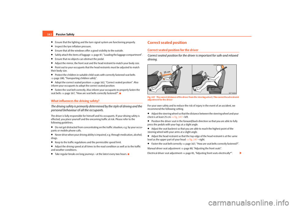
driving.Fig. 147 The correct distance of the driver from the steering wheel / The correct head restraint
adjustment for the driverFor your own safety and to reduce the risk of injury in the event of an accident, we
recommend the following setting.
Adjust the steering wheel so that the distance between the steering wheel and your
chest is at least 25 cm fig. 147 - left.
Position the driver seat in the forward/back direction so that you are able to fully
press the pedals with your legs at a slight angle.
Adjust the seat backrest so that you are able to reach the highest point of the
steering wheel with your arms at a slight angle.
Adjust the head restraint so that the top edge of the head restraint is at the same
level as the upper part of your head fig. 147 - right.
Fasten the seat belt correctly page 167, “How are seat belts correctly fastened?”.
Manual driver se at adjustment page 80, “Adjusting the front seats”.
Electrical driver seat adjustment page 81, “Adjusting front seats electrically*”.
s3fg.2.book Page 162 Friday, April 30, 2010 12:17 PM
Page 244 of 287

Breakdown assistance243
Using the system
Safety
Driving Tips
General Maintenance
Breakdown assistance
Technical Data
– Release the clutch particularly gently wh
en starting off or depress the accelerator
particularly gently if your vehicle is fitted with an automatic gearbox.
Driver of the towed vehicle– Switch the ignition on so that the steeri ng wheel is not blocked and you can also
operate the turn signal lights, the headlight flasher, the windscreen wipers and
windscreen washer system.
– Take the vehicle out of gear or move the selector lever into position N if your
vehicle is fitted with an automatic gearbox.
– Note that the brake servo unit and power steering only operate if the engine is running. You will require significantly grea ter physical force to depress the brake
pedal and to steer th e vehicle if the engine is not running.
– Ensure that the tow rope is always kept taught.
Tow rope or tow bar
A tow bar is safest way of towing a vehicle an d also minimizes any shocks. You can use
a tow rope only if a suitable tow bar is not available.
The tow rope must be elastic to protect the vehicle. Thus one should only use plastic
fibre rope or a rope made out of a similarly elastic material.
Only attach the tow rope to the towing eyes provided for this purpose page 243
and page 244.
Driving style
Towing another vehicle requires a certain am ount of practice. Both drivers should be
familiar with the particular points about to wing a vehicle. Unskilled drivers should not
attempt to tow in another vehicle or to be towed in.
One should be constantly vigi lant not to allow impermissibly high towing forces or
jerky loadings. There is always a risk of excessive stresses and damage resulting at the
points to which you attach the tow rope or tow bar when you attempt to tow a vehicle
which is not standing on a paved road.
Caution
If the gearbox of your vehicle no longer contains any oil because of a defect, your
vehicle must only be towed in with the driven wheels raised clear of the ground, or on
a special vehicle transporter or trailer.
Note
Please comply with any national legal provisions particularly regarding the
switched on signal systems, when towi ng in or tow-starting another vehicle.
The tow rope must not be twisted as it may in certain circumstances result in the
front towing eye being unscrewed out of your vehicle.
Front towing eye
The towing eye is stored in th e box for the vehicle tool kit.Fig. 203 Front bumper: Removing the cover / installing the towing eye– Take the cover out of the front bumper fig. 203 - left.
– Screw in the towing eye by hand to the left up to the stop fig. 203 - right and
tighten it as much as po ssible. For tightening, we recommend that you use for
example the wheel wrench*, the lashing eye of another vehicle or a similar object
which you can push through the eye.
– Put the cover in place after screwing out the towing eye again and press into place.
The cover must engage firmly.
s3fg.2.book Page 243 Friday, April 30, 2010 12:17 PM
Page 249 of 287
Fuses and light bulbs
248
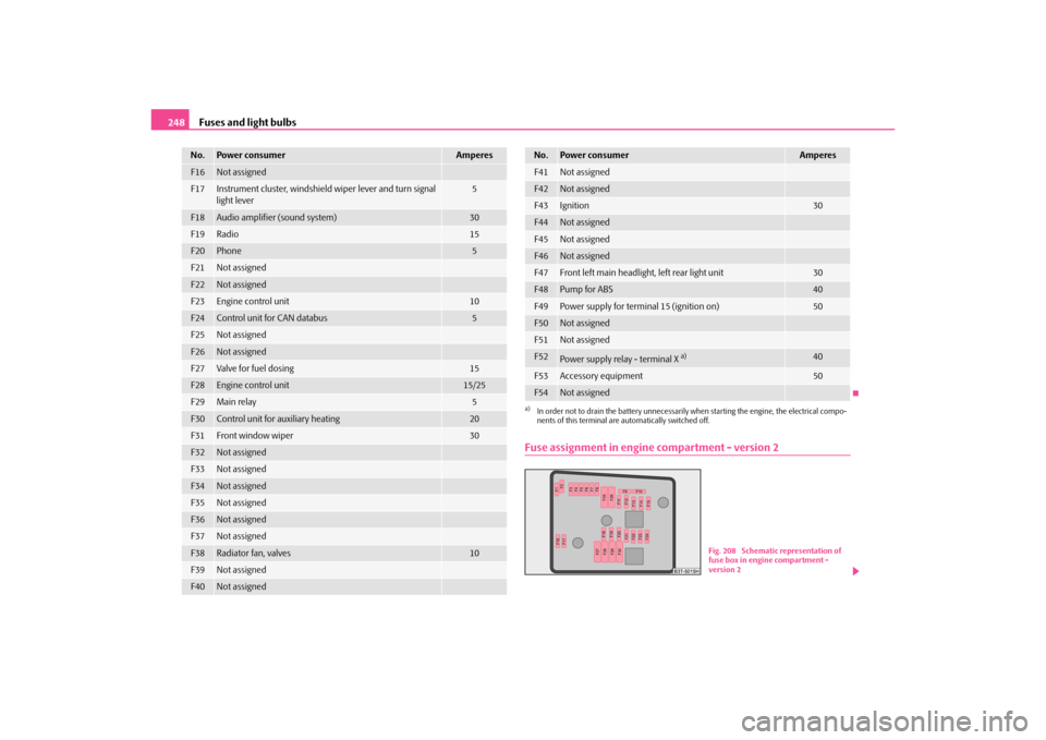
Fuse assignment in engine compartment - version 2
F16
Not assigned
F17
Instrument cluster, windshield wiper lever and turn signal
light lever
5
F18
Audio amplifier (sound system)
30
F19
Radio
15
F20
Phone
5
F21
Not assigned
F22
Not assigned
F23
Engine control unit
10
F24
Control unit for CAN databus
5
F25
Not assigned
F26
Not assigned
F27
Va lve for f uel d osi ng
15
F28
Engine control unit
15/25
F29
Main relay
5
F30
Control unit for auxiliary heating
20
F31
Front window wiper
30
F32
Not assigned
F33
Not assigned
F34
Not assigned
F35
Not assigned
F36
Not assigned
F37
Not assigned
F38
Radiator fan, valves
10
F39
Not assigned
F40
Not assigned
No.
Power consumer
Amperes
F41
Not assigned
F42
Not assigned
F43
Ignition
30
F44
Not assigned
F45
Not assigned
F46
Not assigned
F47
Front left main headlight, left rear light unit
30
F48
Pump for ABS
40
F49
Power supply for terminal 15 (ignition on)
50
F50
Not assigned
F51
Not assigned
F52
Power supply relay - terminal X
a)
40
F53
Accessory equipment
50
F54
Not assigned
a)In order not to drain the battery unnecessarily when starting the engine, the electrical compo-
nents of this terminal are automatically switched off.No.
Power consumer
Amperes
Fig. 208 Schematic representation of
fuse box in engine compartment -
version 2
s3fg.2.book Page 248 Friday, April 30, 2010 12:17 PM
Page 250 of 287
Fuses and light bulbs249
Using the system
Safety
Driving Tips
General Maintenance
Breakdown assistance
Technical Data
Certain electrical components are only standard on certain vehicle model versions or
only suppliable as optional
equipment for certain models.
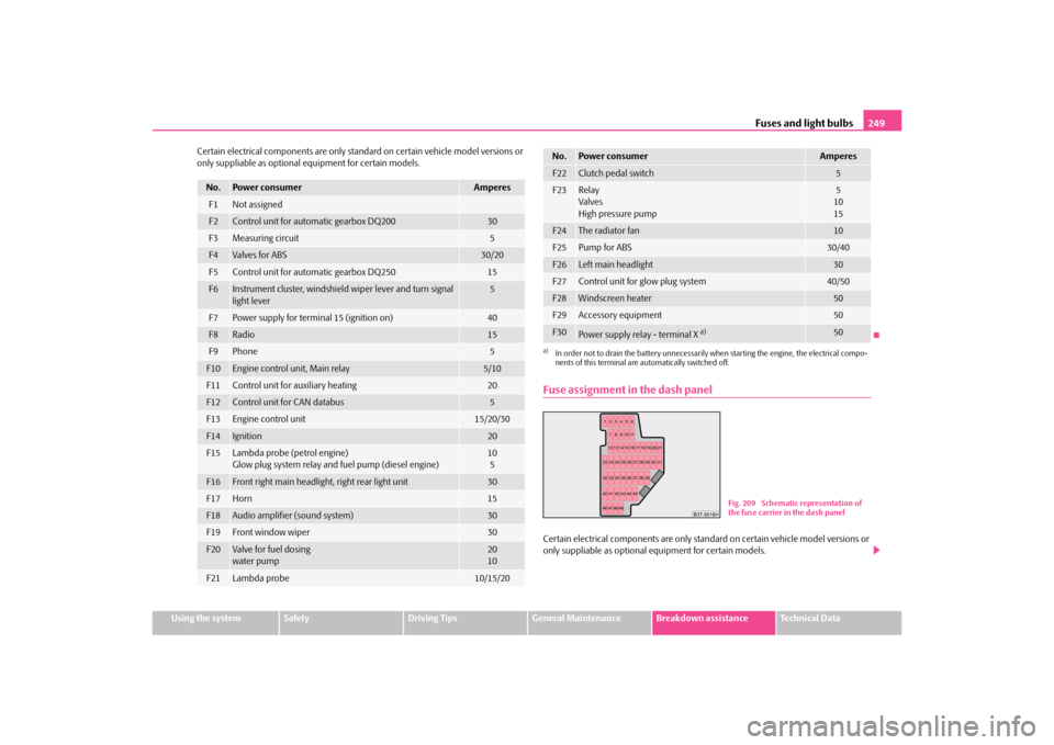
Fuse assignment in the dash panelCertain electrical components are only stan dard on certain vehicle model versions or
only suppliable as optional equipment for certain models.
No.
Power consumer
Amperes
F1
Not assigned
F2
Control unit for automatic gearbox DQ200
30
F3
Measuring circuit
5
F4
Va lve s for AB S
30/20
F5
Control unit for automatic gearbox DQ250
15
F6
Instrument cluster, windshield wiper lever and turn signal
light lever
5
F7
Power supply for terminal 15 (ignition on)
40
F8
Radio
15
F9
Phone
5
F10
Engine control unit, Main relay
5/10
F11
Control unit for auxiliary heating
20
F12
Control unit for CAN databus
5
F13
Engine control unit
15/20/30
F14
Ignition
20
F15
Lambda probe (petrol engine)
Glow plug system relay and fuel pump (diesel engine)
10
5
F16
Front right main headlight, right rear light unit
30
F17
Horn
15
F18
Audio amplifier (sound system)
30
F19
Front window wiper
30
F20
Va lve for f uel d osi ng
water pump
20
10
F21
Lambda probe
10/15/20
F22
Clutch pedal switch
5
F23
Relay
Valves
High pressure pump
5
10
15
F24
The radiator fan
10
F25
Pump for ABS
30/40
F26
Left main headlight
30
F27
Control unit for glow plug system
40/50
F28
Windscreen heater
50
F29
Accessory equipment
50
F30
Power supply relay - terminal X
a)
50
a)In order not to drain the battery unnecessarily wh en starting the engine, the electrical compo-
nents of this terminal are automatically switched off.No.
Power consumer
Amperes
Fig. 209 Schematic representation of
the fuse carrier in the dash panel
s3fg.2.book Page 249 Friday, April 30, 2010 12:17 PM
Page 252 of 287
Fuses and light bulbs251
Using the system
Safety
Driving Tips
General Maintenance
Breakdown assistance
Technical Data
Electrically adjustable seats are protected by
automatic circuit breakers, which
switch on again automatically after a few seconds after the overload has been
eliminated.
BulbsChanging bulbsThe relevant lamp must always be switch ed off before a light bulb is replaced.
Defect light bulbs should only be replaced with light bulbs of the same type. The desig-
nation is located on the ligh t socket or the glass bulb.
Changing certain bulbs is not something whic h you can do yourself, but requires to be
done by a specialist. Other parts of the vehicle must be removed in order to change the
light bulbs. This applies, in particular, to bulbs which can only be reached from the
engine compartment.
We therefore recommend that you have an y bulbs changed by an authorised Škoda
Service Partner or, in exceptional cases, by calling on other professional assistance.
Please note that the engine compartment is a hazardous area page 216, “Working
in the engine compartment”.
We recommend that you always have a small box of replacement bulbs in your vehicle.
You can purchase replacement bulbs from th e range of the Škoda original accessories 18). A stowage place for the bulbs is located in the box in the spare wheel.
Fitted with a xenon headlight
Change of bulbs on vehicles with Xenon lights (low beam lights, parking lights and
main beam lights) should be undertaken by a specialist garage.
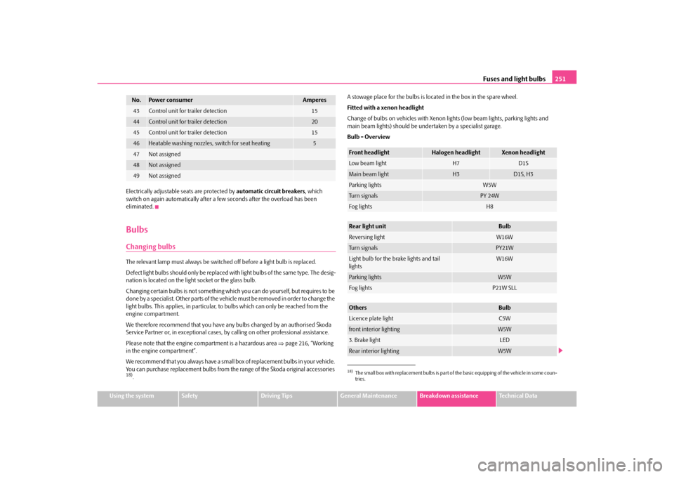
Bulb - Overview43
Control unit for trailer detection
15
44
Control unit for trailer detection
20
45
Control unit for trailer detection
15
46
Heatable washing nozzles, switch for seat heating
5
47
Not assigned
48
Not assigned
49
Not assigned
No.
Power consumer
Amperes
18)The small box with replacement bulbs is part of
the basic equipping of the vehicle in some coun-
tries.Front headlight
Halogen headlight
Xenon headlight
Low beam light
H7
D1S
Main beam light
H3
D1S, H3
Parking lights
W5W
Turn signals
PY 24W
Fog lights
H8
Rear light unit
Bulb
Reversing light
W16W
Turn signals
PY21W
Light bulb for the brake lights and tail
lights
W16W
Parking lights
W5W
Fog lights
P21W SLL
Others
Bulb
Licence plate light
C5W
front interior lighting
W5W
3. Brake light
LED
Rear interior lighting
W5W
s3fg.2.book Page 251 Friday, April 30, 2010 12:17 PM
Page 253 of 287
Fuses and light bulbs
252WARNING
Bulbs H7 and H3 are pressurised and may burst when changing the bulb -
risk of injury!
It is recommended to wear gloves and safety glasses when changing a bulb.
Gas discharge bulbs* (xenon bulbs) operate with a high voltage, profes-
sional knowledge is required - danger to life!Caution
Do not take hold of the glass bulb with naked fingers (even the smallest amount of dirt
reduces the working life of the light bulb). Use a clean cloth, serviette or something
similar.
Note
This Owner's Manual only describes the replacement of bulbs where it is assumed that
no major complications will arise. Other light bulbs should be replaced by your
specialist garage.
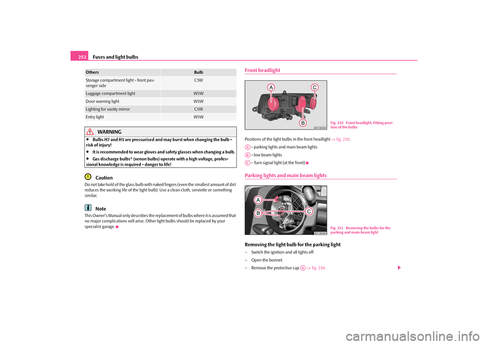
Front headlightPositions of the light bulbs in the front headlight fig. 210 .
- parking lights and main beam lights
- low beam lights
- Turn signal light (at the front)Parking lights and main beam lightsRemoving the light bulb for the parking light– Switch the ignition and all lights off.
– Open the bonnet.
– Remove the protective cap fig. 210.
Storage compartment light - front pas-
senger side
C3W
Luggage compartment light
W5W
Door warning light
W5W
Lighting for vanity mirror
C5W
Entry light
W5W
Others
Bulb
Fig. 210 Front headlight: Fitting posi-
tion of the bulbs
AAABAC
Fig. 211 Removing the bulbs for the
parking and main beam light
AA
s3fg.2.book Page 252 Friday, April 30, 2010 12:17 PM
Page 256 of 287
Fuses and light bulbs255
Using the system
Safety
Driving Tips
General Maintenance
Breakdown assistance
Technical Data
Change bulbs in the outer part of the rear light unit– To change a bulb, turn its fixture to the left up to the top and take it out.
– Change the bulb, insert again the fixture with the bulb into the housing and turn it
to the right up to the stop.Change bulbs in the inner part of the rear light unit– To change a bulb of the reversing light page 254, fig. 215 , pull the defective
bulb out of the fixture and insert a new one.
– To change the bulb of the rear fog light page 254, fig. 215 , turn the defective
bulb to the left up to the stop and take it out.
– Press a new light bulb into the socket and turn the light bulb to the right as far as
the stop.
Fitting position of the bulbs in the outer rear light unit page 254, fig. 215 - left.
- Turn signal lights
- Parking lights / Brake light
- Parking lights
Fitting position of the bulbs in the inner rear light unit page 254, fig. 215 - right.
- Reversing light
- Rear fog light
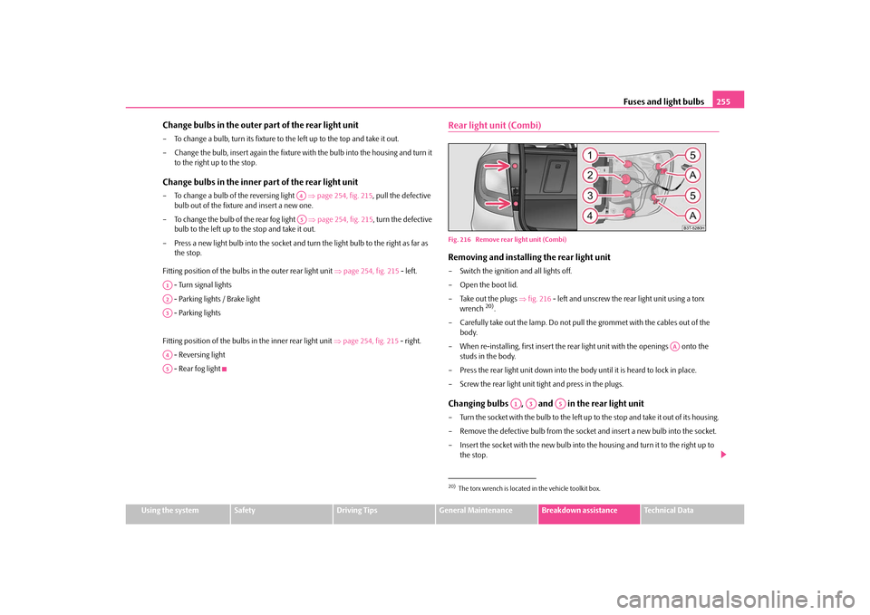
Rear light unit (Combi)Fig. 216 Remove rear light unit (Combi)Removing and installing the rear light unit– Switch the ignition and all lights off.
– Open the boot lid.
– Take out the plugs fig. 216 - left and unscrew the rear light unit using a torx
wrench
20).
– Carefully take out the lamp. Do not pull the grommet with the cables out of the
body.
– When re-installing, first insert the rear light unit with the openings onto the studs in the body.
– Press the rear light unit down into the body until it is heard to lock in place.
– Screw the rear light unit tight and press in the plugs.
Changing bulbs , and in the rear light unit– Turn the socket with the bulb to the left up to the stop and take it out of its housing.
– Remove the defective bulb from the socket and insert a new bulb into the socket.
– Insert the socket with the new bulb into the housing and turn it to the right up to the stop.
A4A5
A1A2A3A4A5
20)The torx wrench is located in the vehicle toolkit box.
AA
A1
A3
A5
s3fg.2.book Page 255 Friday, April 30, 2010 12:17 PM
Page 257 of 287
Fuses and light bulbs
256
Changing bulbs and in the rear light unit
– Turn the socket with the bulb to the left up to the stop and take it out of its housing.
– Press in the defective bulb, turn it to the left up to the stop and take it out.
– Insert a new bulb into the socket, press it in and turn the bulb to the right up to the
stop.
– Insert the socket with the new bulb into the housing and turn it to the right up to the stop.
Fitting position of the bulbs page 255, fig. 216.
- Parking lights / Reversing light
- Reversing light
- Turn signal lights
- Parking lights / Brake light
- Parking lights
Caution
When removing and installing the rear ligh t unit make sure not to damage the paint-
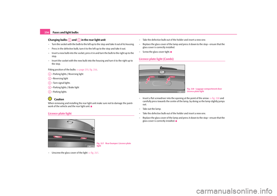
work of the vehicle and the rear light unit.Licence plate light– Unscrew the glass cover of the light fig. 217 . – Take the defective bulb out of the holder and insert a new one.
– Replace the glass cover of the lamp and press it down to the stop - ensure that the
glass cover is correctly installed.
– Screw the glass cover tight.
Licence plate light (Combi)– Insert a flat screwdriver into the opening at the point of the arrow fig. 218 and
carefully press towards the centre of the lamp, by doing so the lamp slightly jumps
out.
– Take out the lamp.
– Take the defective bulb out of the holder and insert a new one.
– Replace the glass cover of the lamp and press it down to the stop - ensure that the glass cover is correctly installed.
A2
A4
A1A2A3A4A5
Fig. 217 Rear bumper: Licence plate
light
Fig. 218 Luggage compartment door
Licence plate light
s3fg.2.book Page 256 Friday, April 30, 2010 12:17 PM