boot SKODA SUPERB 2010 2.G / (B6/3T) Owner's Guide
[x] Cancel search | Manufacturer: SKODA, Model Year: 2010, Model line: SUPERB, Model: SKODA SUPERB 2010 2.G / (B6/3T)Pages: 287, PDF Size: 16.59 MB
Page 71 of 287
Lights and Visibility
70
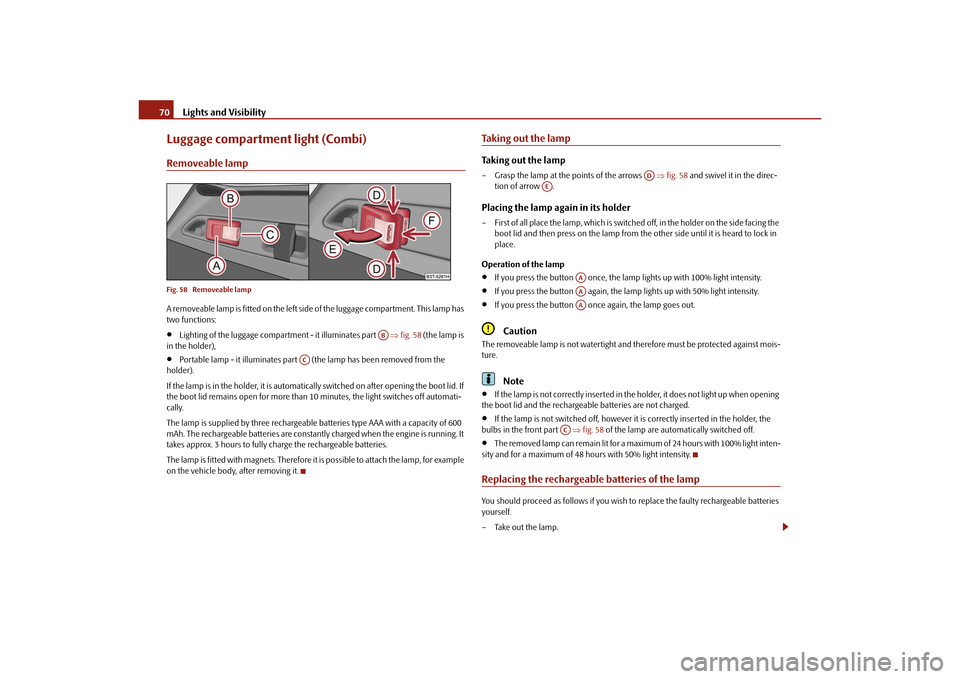
Luggage compartment light (Combi)Removeable lampFig. 58 Removeable lampA removeable lamp is fitted on the left side of the luggage compartment. This lamp has
two functions:
Lighting of the luggage compartment - it illuminates part fig. 58 (the lamp is
in the holder),
Portable lamp - it illuminates part (the lamp has been removed from the
holder).
If the lamp is in the holder, it is automatically switched on after opening the boot lid. If
the boot lid remains open for more than 10 minutes, the light switches off automati-
cally.
The lamp is supplied by three rechargeable batteries type AAA with a capacity of 600
mAh. The rechargeable batteries are constantly charged when the engine is running. It
takes approx. 3 hours to fully charge the rechargeable batteries.
The lamp is fitted with magnets. Therefore it is possible to attach the lamp, for example
on the vehicle body, after removing it.
Taking out the lampTaking out the lamp– Grasp the lamp at the points of the arrows fig. 58 and swivel it in the direc-
tion of arrow .Placing the lamp again in its holder– First of all place the lamp, which is switched off, in the holder on the side facing the
boot lid and then press on the lamp from th e other side until it is heard to lock in
place.
Operation of the lamp
If you press the button once, the lamp lights up with 100% light intensity.
If you press the button again, the lamp lights up with 50% light intensity.
If you press the button once again, the lamp goes out.Caution
The removeable lamp is not watertight and therefore must be protected against mois-
ture.
Note
If the lamp is not correctly inserted in the holder, it does not light up when opening
the boot lid and the rechargeable batteries are not charged.
If the lamp is not switched off, however it is correctly inserted in the holder, the
bulbs in the front part fig. 58 of the lamp are automatically switched off.
The removed lamp can remain lit for a maximum of 24 hours with 100% light inten-
sity and for a maximum of 48 hours with 50% light intensity.
Replacing the rechargeable batteries of the lampYou should proceed as follows if you wish to replace the faulty rechargeable batteries
yourself.
– Take out the lamp.
AB
AC
AD
AE
AAAAAA
AC
s3fg.2.book Page 70 Friday, April 30, 2010 12:17 PM
Page 75 of 287
Lights and Visibility
74
Automatic wipe/wash for windscreen
– Pull the lever towards the steering wheel into sprung position , the wash system
sprays immediately, the windscreen wiper starts wiping a little later. The wash
system and the windscreen wiper operate simultaneously at a speed of more than
120 km/h.
– Release the lever. The windscreen wash system stops and the wiper continues for another 3 - 4 wiper strokes (depending on the period of spraying of the wind-
screen). At a speed of more than 2 km/h , the wiper wipes once again* 5 seconds
after the last wiper stroke in order to wipe the last drops from the windscreen. This
function can be activated/deacti vated by a specialist garage.Rain sensor*– Move the lever into position .
– You can set the sensitivity of the sensor individually with switch .Wiping the rear window pane* (Combi)– Push the lever away from the st eering wheel into position page 73, fig. 63,
the widescreen wiper will operate every 6 seconds.Automatic wipe/wash for the rear window pane* (Combi)– Press the lever from the steering wheel forward into the sprung position , the wash system sprays immediately, the windscreen wiper starts wiping a little later.
As long as you hold the lever in this position, the wiper operates as well as the wash
system.
– Letting go of the lever will cause the windscreen wash system to stop and the wiper to continue for another 2 - 3 wiper strokes (depending on the period of spraying of
the windscreen). The lever will stay in position after releasing it.Switching windscreen wipers off– Move the lever back into its home position .
After the windscreen wiper switches off each time or the ignition switches off for the
third time, the position of the windscreen wiper changes, this counteracts an early
fatigue of the wiper rubbers. The windscreen wipers and the wash system on
ly operate if the ignition is switched on
and the bonnet is closed.
The rear window wiper operates only if the boot lid is closed.
If the intermittent wipe is switched on, the intervals are also controlled depending on
speed.
The rain sensor* automatically regulates the break between the individual wiper
strokes depending on the intensity of the rain.
The rear window will be wiped again if the front window wipers are on when reverse
gear is selected.
The windscreen washer nozzles are heated* when the ignition is switched on.
Top up with wash liquid page 226.
Winter position
If the windscreen wipers are in rest position, they cannot be folded out from the wind-
screen. For this reason we recommend adjust ing the windscreen wipers in winter so
that they can be folded out from the windscre en easily. You can set this rest position as
follows.
Switch on the windscreen wipers.
Switch off the ignition. The windscreen wipers remain in the position in which they
were when switching off the ignition.
You can also use the service position as a winter position.
WARNING
Properly maintained windscreen wiper blades are essential for clear visi-
bility and safe driving page 76.
Do not use the windscreen washer sy stem at low temperatures, without
heating the windscreen beforehand. Otherwise the window cleaner could
freeze on the windscreen and re strict the view to the front.
The rain sensor only operates as a su pport. The driver is not released from
the responsibility to set the function of the windscreen wipers manually
depending on the visibility conditions.
A5
A1
AA
A6
A7
A6
A0
s3fg.2.book Page 74 Friday, April 30, 2010 12:17 PM
Page 89 of 287

Seats and Stowage
88
Loose objects in the passenger compartment can be thrown forward during
a sudden manoeuvre or in case of an accident and can injure the occupants or
other oncoming traffic. This risk is still increased, if the objects which are flying
around are hit by a deployed airbag. In this case, the objects which are thrown
back can injure the occupants - hazard.
Please note that the handling properties of your vehicle may be affected
when transporting heavy objects as a result of the displacement of the centre of
gravity. The speed and style of driv ing must be adjusted accordingly.
The items carried in the luggage compar tment should be stowed in such a
way that no objects are able to slip fo rward if there are any sudden driving or
braking manoeuvres undertaken - risk of injury!
Never drive with the boot lid fully open ed or slightly ajar otherwise exhaust
gases may get into the interior of the vehicle - risk of poisoning!
On no account exceed the permissible axle loads and the permissible gross
weight of the vehicle - risk of accident!
Never transport occupants in the luggage compartment!Caution
Make sure that transported objects with sharp edges do not damage the following:
heating elements in the rear window,
elements of the aerial integrated in the rear window (Superb),
elements of the aerial integrated in the rear side windows (Combi).Note
Tyre pressure must be adjusted to the load page 228, fig. 189.Vehicles of category N1On vehicles of the category N1, which are not fitted with a protective grille, a lashing
set which complies with the standard EN 12195 (1 - 4) must be used for fastening the
load.
Lashing eyesEyes are located on the sides of the luggage compartment for lashing the goods to be
loaded.
You can also attach a floor fixing net* to these eyes for holding small objects.
WARNING
The load to be transported must be fixed in place in such a way that it cannot
move during the journey and when braking.
If the items of luggage or objects are attached to the lashing eyes with
unsuitable or damaged lashing straps, inju ries can occur in the event of braking
manoeuvres or accidents. In order to prevent the items of luggage being thrown
forward, always use suitable lashing st raps which are firmly attached to the
lashing eyes.
WARNING (continued)
Fig. 77 Luggage compartment: Lashing
eyes
s3fg.2.book Page 88 Friday, April 30, 2010 12:17 PM
Page 91 of 287

Seats and Stowage
90
Fixing floor covering of the luggage compartmentFig. 81 Luggage compartment: Fixing of the fl oor covering / luggage compartment: Fixing of
the floor covering (Combi)A loop fig. 81 left is located on the floor covering of the luggage compartment and
a hook fig. 81 right is located on the underside of the floor covering. When handling
the spare wheel*, you can raise the floor covering and fix it on a hook at the luggage
compartment cover.Luggage net*The luggage net is designed for the tranportation of lighter objects.
WARNING
In the storage net you must only stow objects (up to a total weight of 1.5 kg).
Heavy objects are not secured sufficiently - risk of injury!
No objects with sharp edges should be stowed in the luggage net, because
they can damage the luggage net.
Luggage compartment cover
You can use the luggage compartment cover behind the head
restraints for storing light and soft items.The luggage compartment cover can be remo ved as required if one must transport
bulky goods.
– Unhook the support straps fig. 83.
– Place the cover in th e horizontal position.
– Pull the cover out of the holder horizontally to the rear.
– Install again by pushing the luggage compartment cover forwards into the holder and hanging the support straps on the boot lid.
You can stow the removed luggage compartmen t cover behind the rear seat backrest.
WARNING
No objects should be placed on the luggage compartment cover, the vehicle
occupants could be endangered if th ere is sudden braking or the vehicle
collides with something.
Fig. 82 Luggage compartment: Luggage
net
WARNING (continued)
Fig. 83 Removing the luggage compart-
ment cover
A1
A2
A2
A1
s3fg.2.book Page 90 Friday, April 30, 2010 12:17 PM
Page 92 of 287

Seats and Stowage91
Using the system
Safety
Driving Tips
General Maintenance
Breakdown assistance
Technical Data
Caution
Please ensure that the heating elements of the rear window heater are not damaged
as a result of objects placed in this area.
Note
Opening the tailgate also lifts up the luggage compartment cover.Foldable luggage compartment cover (Combi)Fig. 84 Luggage compartment: foldable lugga ge compartment cover / removing foldable
luggage compartment coverPulling out– Pull the foldable luggage compartment cover as far as the stop into the secured
position fig. 84 .Folding– Press the cover in the handle area in direction of arrow fig. 84 , the cover rolls
up automatically into position . The cove r is fully rolled up by pressing once
again.Removing– The fully folded luggage compartment cover can be removed to transport bulky goods by pressing on the side of the cross rod in direction of arrow fig. 84
and taking it out by moving it in direction of arrow .
WARNING
No objects should be placed on the luggage compartment cover.Automatic foldable luggage compartment cover* (Combi)
The automatic rolling up of the fo ldable luggage compartment cover
enables an easier entry in to the luggage compartment.– Open the boot lid. The foldable luggage compartment cover rolls up automatically
in the position page 91, fig. 84 .
– The cover rolls up fully by pressing the cover in the handle area in direction of
arrow .
When the boot lid is opened quickly, the automatic rolling up of the foldable luggage
compartment cover is blocked for a delay time of approx. 2 seconds.
The function of the automatic rolling up of the foldable luggage compartment cover
can be activated/deactivated in the information display* in the menu:
SETUP
Autom. blindWARNING
No objects should be placed on the luggage compartment cover.
A2
A3
A1
A4
A5
A1
A3
s3fg.2.book Page 91 Friday, April 30, 2010 12:17 PM
Page 98 of 287
Seats and Stowage97
Using the system
Safety
Driving Tips
General Maintenance
Breakdown assistance
Technical Data
– Push the net partition housing in the oppo
site direction of arrow as far as the
stop.
– Fold the rear seats back into their original position.
WARNING
Pay attention that the rear seat backrest is correctly interlocked. It is only then
that the three-point seat belt for the middle seat can reliably fulfil its function.The roof rack*DescriptionPay attention to the following points if you wish to transport luggage or other items on
the roof of your vehicle:
A special roof luggage rack system was de veloped for the vehicle, that is why you
should only use a roof luggage rack which has been released for use by Škoda Auto.
The base carrier is the basis for a complete roof luggage rack system. Separate
additional holders are required for safety reasons for transporting luggage, bikes, surf-
boards, skis and boats.
The basic version of the roof luggage rack system and further components are
obtainable as accessories from the authorised Škoda Service Partners.Caution
If you use other roof rack systems or if the roof bars are not properly fitted, then any
damage which may result to your car is not covered by the warranty agreements. It is
therefore essential to pay attention to the fitting instructions supplied with the roof
luggage rack system.
On models fitted with a power sliding/ti lting roof or a panoramic sliding roof,
ensure that the opened sliding/tilting roof or the panoramic sliding roof does not strike
any items of luggage transported on the roof.
Ensure that the opened boot lid does not collide with the roof load.
For the sake of the environment
The increased aerodynamic drag results in a higher fuel consumption. One should
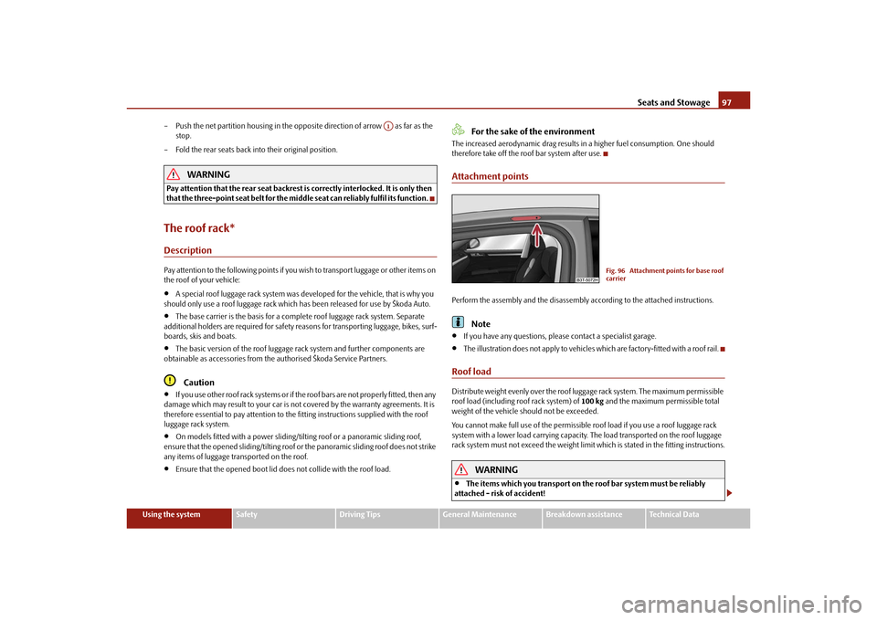
therefore take off the roof bar system after use.Attachment pointsPerform the assembly and the disassembly according to the attached instructions.
Note
If you have any questions, please contact a specialist garage.
The illustration does not apply to vehicles which are factory-fitted with a roof rail.
Roof loadDistribute weight evenly over the roof luggage rack system. The maximum permissible
roof load (including roof rack system) of 100 kg and the maximum permissible total
weight of the vehicle should not be exceeded.
You cannot make full use of th e permissible roof load if you use a roof luggage rack
system with a lower load carr ying capacity. The load transported on the roof luggage
rack system must not exceed the weight limit which is stated in the fitting instructions.
WARNING
The items which you transport on the roof bar system must be reliably
attached - risk of accident!
A1
Fig. 96 Attachment points for base roof
carrier
s3fg.2.book Page 97 Friday, April 30, 2010 12:17 PM
Page 107 of 287
Seats and Stowage
106WARNING
The opening for the skis is solely used for transporting skis which are placed in
a properly secured removeable through-loading bag page 106.Through-loading bag*
The removeable through-loading bag is solely used for transporting
skis.Loading– Open the boot lid.
– Fold the rear armrest and the cover in the seat backrest downwards page 105.
– Place the empty through-loading bag in such a way that the end of the bag with the
zip lies in the boot.
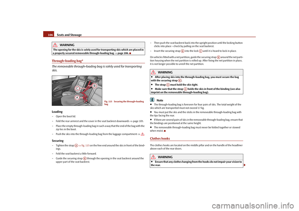
– Push the skis into the through-loading bag from the luggage compartment .Securing–Tighten the strap fig. 115 on the free end around the skis in front of the bind-
ings.
– Fold the seat backrest a little forward.
– Guide the securing strap through the op ening in the seat backrest around the
upper part of the seat backrest. – Then push the seat backrest back into th
e upright position until the locking button
clicks into place - check by pulling on the seat backrest.
– Insert the securing strap into the lock until it is heard to lock in place.
On vehicles fitted with a net partition, gu ide the securing strap around the net parti-
tion housing when the net partition is rolled up. After fixing the net partition in place,
it is not longer possible to unroll the net partition.
WARNING
After placing skis into the through-loading bag, you must secure the bag
with the securing strap .
The strap must hold the skis tight.
Make sure that the strap holds the sk is in front of the binding (see also
imprint on the removeable through-loading bag).Note
The through-loading bag is foreseen for four pairs of skis. The total weight of the
skis which are transported must not exceed 17 kg.
You must put the skis and the sticks in the removeable through-loading bag with
the tips facing the rear.
If there are several pairs of skis in the removeable through-loading bag, ensure that
the bindings are positioned at the same height.
The removeable through-loading bag must never be folded together or stowed
when moist.
Clothes hooksThe clothes hooks are located on the middle pi llar and on the handle of the headliner
above each of the rear doors.
WARNING
Ensure that any clothes hanging from the hooks do not impair your vision to
the rear.
Fig. 115 Securing the through-loading
bag
AA
AB
AB
AC
AB
AB
AA
AA
s3fg.2.book Page 106 Friday, April 30, 2010 12:17 PM
Page 209 of 287
Taking care of your vehicle and cleaning the vehicle
208
Do not use window leathers which you have us ed to polish the vehicle body to dry off
the windows. Residues of preservatives in the window leather can dirty the window
and reduce visibility.
Do not affix any stickers over the inside of the rear window to avoid damage to the
heating elements of the rear window heater .
We recommend using a preserva tive from Škoda genuine accessories offered by your
Škoda dealer.
Caution
Never remove snow or ice from the glass parts with warm or hot water - risk of forma-
tion of cracks in the glass.The headlight lensesPlease do not use any aggressi ve cleaning or chemical solvent products for cleaning
the front headlights - risk of damage to the plastic lenses. Please use soap and clean
warm water.
Caution
Never wipe the headlights dry and do not use any sharp objects for cleaning the plastic
lenses, this may result in damage to the protective paintwork and consequently in
formation of cracks on the headlight lenses, e.g through effect of chemical products.Door and window sealsThe rubber seals on the doors, boot lid, bonnet and windows remain supple and last
longer if you treat them from time to time with a rubber care product (e.g. with a spray
with silicone-free oil). You also avoid premature wear of the seals and prevent leakages
in this way. It is also easier to open the doors. Rubber seals which are well cared for also
do not stick together in cold winter weather.Locking cylinderWe recommend that you use the spray from Škoda original accessories with regreasing
and anticorrosive effect for de-icing locking cylinders.
Note
When washing your vehicle, ensure that as little water as possible gets into the locking
cylinders.WheelsSteel wheels
You should also thoroughly wash the wheels and wheel trims when giving your vehicle
its regular wash. This prevents any brake dust, dirt and road salt from sticking to the
wheel hubs. You can remove stubborn brake abrasion adhering to the wheels with an
industrial cleaner. Touch up any damage to the paintwork on the wheels before rust is
able to form.
Light alloy wheels
Regular care of light alloy wh eels is necessary in order to retain their decorative
appearance over long periods. It is particul arly important to remove any road salt and
brake abrasion from light alloy wheels every two weeks, otherwise the light metal will
suffer. Wash thoroughly and then treat the wheels with a protective product for light
alloy wheels which does not contain any acidic componen ts. You should provide the
wheel hubs with a hard wax layer every thre e months. You must not use any products
which cause abrasion when treating the wheel hubs. Any damage to the paint layer on
the wheel hubs must be touched up immediately.
We recommend using a preservative from Šk oda genuine accessories offered by your
Škoda dealer.
WARNING
One should remember when cleaning th e wheels that moisture, ice and road
salt may adversely affect braking ef ficiency - risk of an accident!
Note
Severe layers of dirt on the wheels can also result in wheel imbalance. This may show
itself in the form of a wheel vibration which is transmitted to the steering wheel which,
in certain circumstances, can cause premature wear of the steering. This means it is
necessary to remove the dirt.
s3fg.2.book Page 208 Friday, April 30, 2010 12:17 PM
Page 251 of 287
Fuses and light bulbs
250No.
Power consumer
Amperes
1
Diagnostic socket, engine control unit, fuel pump relay,
fuel pump control unit
7,5
2
Control unit for ABS, ESP, switch for tyre air pressure con-
trol, brake sensor
5
3
Switch and control unit for airbag
5
4
WIV, parking light, dimming mirrors, pressure sensor, tele-
phone preinstallation
5
5
Control unit for headlamp beam adjustment and head-
light swivel, control unit for parking aid, control unit for
park assist
5
6
Instrument cluster, control unit for electromechanical
power steering, Haldex, selector lever lock, power supply
for data bus
5
7
Valve heating, air mass meter
10
8
Control unit for trailer detection
5
9
Relay for auxiliary heating
5
10
Adaptive left main headlight
10
11
Adaptive right main headlight
10
12
Not assigned
13
Diagnostic socket, light switch, rain sensor, clock
7,5
14
Central locking system and bonnet lid
15
15
Central control unit - interior lights
7,5
16
Air conditioning system
7,5
17
Not assigned
18
Not assigned
19
Not assigned
20
KESSY
5
21
KESSY ELV
7,5
22
Air blower for Climatronic
40
23
Front power window, central locking of the front doors
30
24
Selector lever lock
5
25
Rear window heater, relay for auxiliary heating and venti-
lation
30
26
Power socket in the luggage compartment
25
27
Fuel pump relay,
Fuel pump relay, control unit for fuel pump, injection
valves
15
20
28
Electric boot lid
30
29
Preparation for the aftermarket radio
5
30
Not assigned
31
Not assigned
32
Front power window, central locking system of the rear
doors
30
33
Electric sliding/tilting roof
25
34
Alarm, spare horn
5
35
front and rear lighter
25
36
Headlight cleaning system
20
37
Front seat heating
20
38
Heated rear seats
20
39
Not assigned
40
Fan air-conditioning system, re lay for auxiliary heating and
ventilation
40
41
Rear window wiper
10
42
Light switch
5
No.
Power consumer
Amperes
s3fg.2.book Page 250 Friday, April 30, 2010 12:17 PM
Page 255 of 287
Fuses and light bulbs
254
– For the installation, first of all insert the fog light with the interlock to the side far
away from the marking of the vehicle.
– Press into place the headlight onto the si de facing the marking. The spring bolt
must engage firmly.
– In order to reinstall the cover, first of all insert one part of the cover starting on the side facing the fog light. Then press the cover closed on the side facing the marking.
The cover must engage firmly.
- bulb for daylight driving lights*.
- bulb for fog lights.Rear light unitFig. 214 Remove the outer part of the rear light unit / remove the inner part of the rear light
unitRemove and install the outer part of the rear light unit– Switch the ignition and all lights off.
– Open the boot lid.
– Take out the plugs fig. 214 - left and unscrew the rear light unit using a torx
wrench
19).
– Carefully take out the lamp. Do not pull the grommet with the cables out of the
body. – To re-insert the rear light unit, first of all guide it with the support
fig. 215
towards the front onto a bolt on the bodywork.
– Carefully press the rear li ght unit into the bodywork.
– Screw the rear light unit tight and press in the plugs fig. 214 - left.
Remove and install the inner part of the rear light unit– Switch the ignition and all lights off.
– Open the boot lid.
– Take off the cover of the rear light unit on the inner side of the bonnet lid fig. 214
- right.
– Press the spring bolt fig. 214 - right and take the lamp holder out of the housing
of the rear light unit.
– To re-insert the lamp holder, guide it into the housing of the rear light unit.
– Press onto the spring bolt until it is heard to lock.
– Guide the cover of the rear light unit into the inner side of the bonnet lid.
Caution
When removing and installing the rear ligh t unit make sure not to damage the paint-
work of the vehicle and the rear light unit.Changing light bulbs in the rear light unitFig. 215 Outer part of the rear light unit: Bulbs / inner part of the rear light unit: Lamps
19)The torx wrench is located in the vehicle toolkit box.AAAB
AA
s3fg.2.book Page 254 Friday, April 30, 2010 12:17 PM