technical data SKODA SUPERB 2010 2.G / (B6/3T) Service Manual
[x] Cancel search | Manufacturer: SKODA, Model Year: 2010, Model line: SUPERB, Model: SKODA SUPERB 2010 2.G / (B6/3T)Pages: 287, PDF Size: 16.59 MB
Page 82 of 287
Seats and Stowage81
Using the system
Safety
Driving Tips
General Maintenance
Breakdown assistance
Technical Data
Adjusting lumbar support*– Turn the lever until you have set the most comfortable curvature of the seat
upholstery in the area of your spine.
The driver's seat should be adjusted in such a way that the pedals can be fully pressed
to the floor with slightly bent legs.
The seat backrest on the driver's seat should be adjusted in such a way that the upper
point of the steering wheel can be easi ly reached with slightly bent arms.
WARNING
Only adjust the driver seat when the vehicle is stationary - risk of injury!
Take care when adjusting the seat! Adjusting the seat without care can lead
to bruises or injuries.
The seat backrests must not be angled too far back when driving otherwise
this will affect proper operation of the se at belts and of the airbag system - risk
of injury!
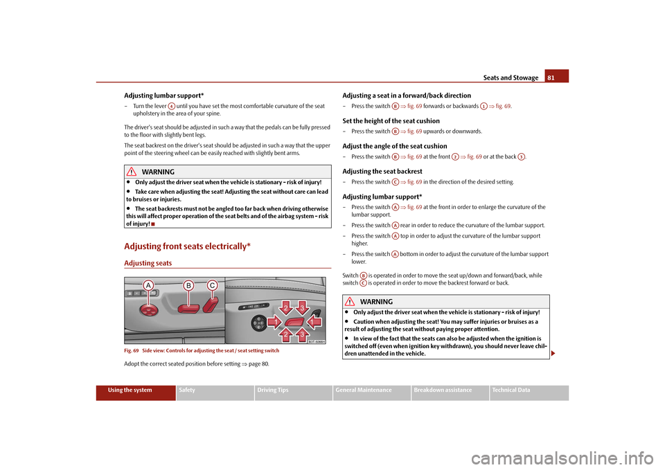
Adjusting front seats electrically*Adjusting seatsFig. 69 Side view: Controls for adju sting the seat / seat setting switchAdopt the correct seated position before setting page 80.
Adjusting a seat in a forward/back direction– Press the switch fig. 69 forwards or backwards fig. 69 .Set the height of the seat cushion– Press the switch fig. 69 upwards or downwards.Adjust the angle of the seat cushion– Press the switch fig. 69 at the front fig. 69 or at the back .Adjusting the seat backrest– Press the switch fig. 69 in the direction of the desired setting.Adjusting lumbar support*– Press the switch fig. 69 at the front in order to enlarge the curvature of the
lumbar support.
– Press the switch rear in order to reduce the curvature of the lumbar support.
– Press the switch top in order to adjust the curvature of the lumbar support higher.
– Press the switch bottom in order to adjust the curvature of the lumbar support lower.
Switch is operated in order to move the seat up/down and forward/back, while
switch is operated in order to move the backrest forward or back.
WARNING
Only adjust the driver seat when the vehicle is stationary - risk of injury!
Caution when adjusting the seat! You ma y suffer injuries or bruises as a
result of adjusting the seat without paying proper attention.
In view of the fact that the seats can also be adjusted when the ignition is
switched off (even when ignition key withdrawn), you should never leave chil-
dren unattended in the vehicle.
A4
AB
A1
ABAB
A2
A3
ACAAAAAAAA
ABAC
s3fg.2.book Page 81 Friday, April 30, 2010 12:17 PM
Page 84 of 287
Seats and Stowage83
Using the system
Safety
Driving Tips
General Maintenance
Breakdown assistance
Technical Data
– Press the unlock button
page 49, after the successful assignment an audible
signal will sound. The setting is stored with the memory button which you have
selected.
Assigning the remote control key to the memory buttons on the KESSY*
systemOn vehicles which are equipped with the KESSY* system, the following procedure for
assigning the remote control key to the memory buttons exists for electrically adjust-
able front seats and mirrors*.
– Switch the ignition off within 10 seconds after storing the setting.
– Open the driver door.
– Press the unlock button on the remo te control key within 10 seconds.
If you wish to be able to retrieve the settings which are stored in the memory by also
using the radio remote control, you have to assign the radio remote control to a
memory button in each case.
If you wish, you can obtain an additional remote control key from an authorised Škoda
Service partner and then assign the remote control key to another memory button.
Note
If the radio remote control had previously been assigned to another memory
button, this setting is then erased by the new assignment.
If you assign the radio remote control to a memory button which has already been
assigned to a radio remote control, the ol d assignment is also replaced by a new
assignment in this case.
The assignment of the radio remote co ntrol to a memory button is retained,
however, after reassigning the seats and exterior mirrors.
After the successful assignment, the turn si gnal lights flash and an audible signal
will sound as a confirmation. The setting is stored with the memory button which you
have selected.
Retrieving settings of the seat and mirrors
You can retrieve the stored settings either with the memory buttons or
with the remote control*.Retrieving settings with memory buttons– In order to retrieve the stored setting, you have two possibilities:
– One-touch automatic memory: briefly press the desired memory button
page 82, fig. 70 . The seat and exterior mirror are moved automatically into the
stored positions (this applies only if the ignition is switched on and the speed is less
than 5 km/h).
– Memory keying : Press and hold the desired memory button pressed long
enough until the seat and the exterior mi rror are moved into the stored positions.Retrieving settings with remote control– If the driver door is closed and the ignition is switched off, briefly press the unlock
button of the radio remote control page 49 and then open the driver door.
– The seat and exterior mirrors now move automatically into the stored positions.Retrieving setting of exterior mirror for reversing*– Turn the rotary knob for the exterior mirror setting into the position
page 77
before engaging the reverse gear.
The mirror returns into its initial position, after the rotary knob is moved out of the
position
and put into another position or if the speed is more than 15 km/h.
Emergency Off
You can interrupt the setting operation at any time, if you operate any button of the
driver seat.
AB
AB
s3fg.2.book Page 83 Friday, April 30, 2010 12:17 PM
Page 86 of 287
Seats and Stowage85
Using the system
Safety
Driving Tips
General Maintenance
Breakdown assistance
Technical Data
– Press the locking button in the direction of arrow
fig. 72 , press simultane-
ously the locking button into the opening using a flat screwdriver with a width
of maximum 5 mm and pull out the head restraint.
– To re-insert the head restraint, push it down into the seat backrest far enough until you hear the locking button engage.
WARNING
The head restraints must be correctly adjusted in order to offer effective
protection for the occupants in the event of an accident.
Do not drive under any circumstance with removed head restraints - risk of
injury.
If the rear seats are occupied, the rear head restraint must not be in the
lower position.
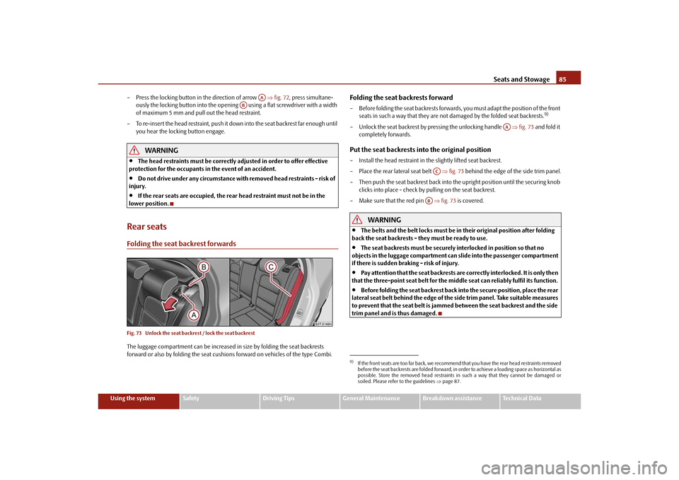
Rear seatsFolding the seat backrest forwardsFig. 73 Unlock the seat back rest / lock the seat backrestThe luggage compartment can be increased in size by folding the seat backrests
forward or also by folding the seat cushions forward on vehicles of the type Combi.
Folding the seat backrests forward– Before folding the seat backrests forwards, you must adapt the position of the front
seats in such a way that they are not damaged by the folded seat backrests.
9)
– Unlock the seat backrest by pressing the unlocking handle fig. 73 and fold it
completely forwards.Put the seat backrests into the original position– Install the head restraint in the slightly lifted seat backrest.
– Place the rear lateral seat belt fig. 73 behind the edge of the side trim panel.
– Then push the seat backrest back into th e upright position until the securing knob
clicks into place - check by pulling on the seat backrest.
– Make sure that the red pin fig. 73 is covered.
WARNING
The belts and the belt locks must be in their original position after folding
back the seat backrests - th ey must be ready to use.
The seat backrests must be securely interlocked in position so that no
objects in the luggage compartment can slide into the passenger compartment
if there is sudden braking - risk of injury.
Pay attention that the seat backrests are correctly interlocked. It is only then
that the three-point seat belt for the middle seat can reliably fulfil its function.
Before folding the seat backrest back into the secure position, place the rear
lateral seat belt behind the edge of the si de trim panel. Take suitable measures
to prevent that the seat belt is jammed between the seat backrest and the side
trim panel and is thus damaged.
AA
AB
9)If the front seats are too far back, we recommend that you have the rear head restraints removed
before the seat backrests are folded forward, in order to achieve a loading space as horizontal as
possible. Store the removed head restraints in such a way that they cannot be damaged or
soiled. Please refer to the guidelines page 87.
AA
AC
AB
s3fg.2.book Page 85 Friday, April 30, 2010 12:17 PM
Page 88 of 287
Seats and Stowage87
Using the system
Safety
Driving Tips
General Maintenance
Breakdown assistance
Technical Data
WARNING
If, as an occupant, you have a subdued pain and/or temp erature sensitivity, e.g.
through medication, paralysis or because of chronic illness (e.g. diabetes), we
recommend not to use the seat heating. Th is can lead to burns on the back, the
posterior and the legs which are difficult to heal. If the seat heating is used, we
recommend to make regular breaks in your journey when driving long
distances, so that in specific cases as mentioned above the body can recuperate
from the stress of the journey. Please consult your doctor, who can evaluate
your specific condition.
Caution
You should not kneel on the seats or otherwise apply pressure at specific points in
order to avoid damaging the heating elements of the seat heaters.
Do not use the seat heating if the seats are not occupied by persons or if objects
are fastened or stored on them, for example a child seat, a bag etc. A fault of the heating
elements in the seat heating can occur.
Do not clean the seats moist page 209.Note
The seat heating should only be switched on when the engine is running. This has
a significant effect of saving on the battery capacity.
If the on-board voltage drops, the seat heating is switched off automatically, in
order to provide sufficient electrical energy for the engine control.
PedalsConcerning a secure depressing of the peda l, you should use only footmats from the
Škoda genuine accessories.
Operation of the pedals must not be hindered!
WARNING
Greater pedal distances may be needed when there is a fault in the brake
system.
Do not place any footmats or other additional floor coverings in the area of
the pedals in order to ensure that all the pedals can be fully depressed and are
able to return unobstructed to their initial position - risk of accident!
There must be no objects on the floor which could roll under the pedals. You
would then no longer be able to apply the brakes, operate the clutch or acceler-
ator - risk of accident!
luggage compartmentLoading the luggage compartmentPlease observe the following in the interest of having good handling characteristics of
your vehicle:
– Distribute the items of luggage as evenly as possible.
– Place heavy objects as far forward as possible.
– Attach the items of luggage to the lashing eyes or the fixing net* page 88.
In the event of an accident, there is such a high kinetic energy which is produced by
small and light objects that they can cause severe injuries. The magnitude of the kinetic
energy depends on the speed at which the vehicle is travelling and on the weight of the
object. The speed at which the vehicle is trave lling is in this case the more significant
factor.
Example: In the event of a frontal collision at a speed of 50 km/h, an unsecured object
with a weight of 4.5 kg produces an en ergy, which corresponds to 20 times its own
weight. This means that it results in a weight of approx. 90 kg. You can imagine the inju-
ries that can occur, if this “bullet” is flying through the interior compartment and hits
an occupant.
WARNING
Stow the objects in the luggage compartment and attach them to the
lashing eyes.WARNING (continued)
s3fg.2.book Page 87 Friday, April 30, 2010 12:17 PM
Page 90 of 287

Seats and Stowage89
Using the system
Safety
Driving Tips
General Maintenance
Breakdown assistance
Technical Data
Fixing nets - Net programme*Fig. 78 Fixing net: Vertical pocket, floor fixing net and horizontal pocket
Fig. 79 Fixing nets (Combi)Fixing examples for fixing net as horizontal pocket on the left fig. 78 and fig. 79 ,
floor fixing net on the right fig. 78 and vertical pocket on the right fig. 78 and
fig. 79 .
The fixing nets* are stored in the right side storage compartment of the luggage
compartment.
WARNING
The permissible load of the side nets is 3.5 kg. Heavy objects are not secured
sufficiently - risk of injury and net damage!
Caution
Do not place any objects with sharp edges in the nets - risk of net damage.
Note
The hooks page 89, fig. 79 , located on both sides of the luggage compartment,
are only designed for fixing the fixing net.Folding hooksFig. 80 Luggage compartment: folding hook / luggage compartment: folding hook (Combi)Folding hooks for attaching small items of luggage, such as bags etc., are provided on
both sides of the luggage compartment fig. 80 .
An item of luggage weighing up to 7.5 kg can be attached to the hook.
WARNING
Please refer to the following guidelines page 87.
AA
s3fg.2.book Page 89 Friday, April 30, 2010 12:17 PM
Page 92 of 287

Seats and Stowage91
Using the system
Safety
Driving Tips
General Maintenance
Breakdown assistance
Technical Data
Caution
Please ensure that the heating elements of the rear window heater are not damaged
as a result of objects placed in this area.
Note
Opening the tailgate also lifts up the luggage compartment cover.Foldable luggage compartment cover (Combi)Fig. 84 Luggage compartment: foldable lugga ge compartment cover / removing foldable
luggage compartment coverPulling out– Pull the foldable luggage compartment cover as far as the stop into the secured
position fig. 84 .Folding– Press the cover in the handle area in direction of arrow fig. 84 , the cover rolls
up automatically into position . The cove r is fully rolled up by pressing once
again.Removing– The fully folded luggage compartment cover can be removed to transport bulky goods by pressing on the side of the cross rod in direction of arrow fig. 84
and taking it out by moving it in direction of arrow .
WARNING
No objects should be placed on the luggage compartment cover.Automatic foldable luggage compartment cover* (Combi)
The automatic rolling up of the fo ldable luggage compartment cover
enables an easier entry in to the luggage compartment.– Open the boot lid. The foldable luggage compartment cover rolls up automatically
in the position page 91, fig. 84 .
– The cover rolls up fully by pressing the cover in the handle area in direction of
arrow .
When the boot lid is opened quickly, the automatic rolling up of the foldable luggage
compartment cover is blocked for a delay time of approx. 2 seconds.
The function of the automatic rolling up of the foldable luggage compartment cover
can be activated/deactivated in the information display* in the menu:
SETUP
Autom. blindWARNING
No objects should be placed on the luggage compartment cover.
A2
A3
A1
A4
A5
A1
A3
s3fg.2.book Page 91 Friday, April 30, 2010 12:17 PM
Page 94 of 287

Seats and Stowage93
Using the system
Safety
Driving Tips
General Maintenance
Breakdown assistance
Technical Data
Partially pulling out the variable loading floor*Fig. 87 Luggage compartment: partially pulling out the variable loading floorThe variable loading floor can be partially pulled out over the rear bumper. The vari-
able loading floor which is pulled out in such a way is solely used as a seat, for example
for changing shoes. When pulling out the va riable loading floor, the front edge (close
to the rear seats) is lifted at the same ti me. Thus, small objects can no longer fall into
the space between the luggage compartmen t floor and the variable loading floor.
– Grasp the rear par t of the variable floor at the handle, raise it slightly in direction of arrow fig. 87 and pull it over the bumper in direction of arrow until it
engages in the opening fig. 87 .
– Grasp the part of the floor at the handle, raise it slightly in direction of arrow and push it forwards up to the stop in order to push in the variable loading floor.
Caution
Ensure that the raised front edge of the variable loading floor is not damaged.
Dividing the luggage compartment with variable loading floor*The luggage compartment can be divided with the variable loading floor.
– Grasp the rear part of the floor at the handle, raise it in direction of arrow
page 93, fig. 87 and insert the rear edge in one of the openings fig. 88 .
The variable loading floor is secured in the openings against movement.
The variable loading floor can be pulled out some more before dividing the luggage
compartment with the variable loading floor page 93. This enlarges the space
between the rear seats and the separation.
Caution
Ensure that the raised front edge of the variable loading floor is not damaged.
A1
A2
AC
A1
Fig. 88 Divide the luggage compartment
A1
AA
AA
s3fg.2.book Page 93 Friday, April 30, 2010 12:17 PM
Page 96 of 287

Seats and Stowage95
Using the system
Safety
Driving Tips
General Maintenance
Breakdown assistance
Technical Data
Tensioning strap– Insert the holder of the tensioning strap in to the opening of the left or right carrier
rail.
– Press the holder in direction of arrow fig. 91 and push it at the same time in
the desired position, arrow .
– Ensure that the holder is correctly interlocked.
– Place the object which should be fa stened behind the tensioning strap.
– Press the button on the top side of the holder and tighten the strap.
WARNING
The objects in the luggage compartment must be firmly secured with the fixing
set so that they cannot move freely and uncontrollably in order to prevent
damage to objects or injuries to the occupants.
Note
Do not use the fixing set fo r securing objects which mi ght damage the fixing set.
The tensioning strap can also be fully reeled up by pressing the button
fig. 91 .
Moveable lashing eyes* (Combi)Fig. 92 Moveable lashing eyes
Four moveable lashing eyes, which can be used for example for attaching the fixing
net, are located in the luggage compartment.
– Press the button page 95, fig. 92 and push the lashing eye in the desired
position, arrow .
– Fold up the clamp page 95, fig. 92 and fix, for example, the fixing net.Net partition* (Combi)Use the net partition behind the rear seatsPulling out– Pull the net partition at the bracket fig. 93 out of the housing in direction
of the holders .
– Insert the cross rod into one of the mounts and push the cross rod forwards.
– In the same way, fix the cross rod to the other side of the vehicle, mount .Folding– Pull the cross rod back slightly, first on the one side then on the other side and take the cross rod out of the mounts fig. 93 .
– Hold the cross rod in such a way that the net partition can roll up into the housing
slowly and without damage.
A3
A4
A5
A5
A1A2A3
Fig. 93 Pull out the net partition
AA
AB
AC
AC
AC
AC
AB
s3fg.2.book Page 95 Friday, April 30, 2010 12:17 PM
Page 98 of 287
Seats and Stowage97
Using the system
Safety
Driving Tips
General Maintenance
Breakdown assistance
Technical Data
– Push the net partition housing in the oppo
site direction of arrow as far as the
stop.
– Fold the rear seats back into their original position.
WARNING
Pay attention that the rear seat backrest is correctly interlocked. It is only then
that the three-point seat belt for the middle seat can reliably fulfil its function.The roof rack*DescriptionPay attention to the following points if you wish to transport luggage or other items on
the roof of your vehicle:
A special roof luggage rack system was de veloped for the vehicle, that is why you
should only use a roof luggage rack which has been released for use by Škoda Auto.
The base carrier is the basis for a complete roof luggage rack system. Separate
additional holders are required for safety reasons for transporting luggage, bikes, surf-
boards, skis and boats.
The basic version of the roof luggage rack system and further components are
obtainable as accessories from the authorised Škoda Service Partners.Caution
If you use other roof rack systems or if the roof bars are not properly fitted, then any
damage which may result to your car is not covered by the warranty agreements. It is
therefore essential to pay attention to the fitting instructions supplied with the roof
luggage rack system.
On models fitted with a power sliding/ti lting roof or a panoramic sliding roof,
ensure that the opened sliding/tilting roof or the panoramic sliding roof does not strike
any items of luggage transported on the roof.
Ensure that the opened boot lid does not collide with the roof load.
For the sake of the environment
The increased aerodynamic drag results in a higher fuel consumption. One should
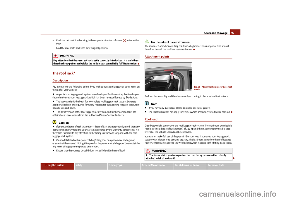
therefore take off the roof bar system after use.Attachment pointsPerform the assembly and the disassembly according to the attached instructions.
Note
If you have any questions, please contact a specialist garage.
The illustration does not apply to vehicles which are factory-fitted with a roof rail.
Roof loadDistribute weight evenly over the roof luggage rack system. The maximum permissible
roof load (including roof rack system) of 100 kg and the maximum permissible total
weight of the vehicle should not be exceeded.
You cannot make full use of th e permissible roof load if you use a roof luggage rack
system with a lower load carr ying capacity. The load transported on the roof luggage
rack system must not exceed the weight limit which is stated in the fitting instructions.
WARNING
The items which you transport on the roof bar system must be reliably
attached - risk of accident!
A1
Fig. 96 Attachment points for base roof
carrier
s3fg.2.book Page 97 Friday, April 30, 2010 12:17 PM
Page 100 of 287

Seats and Stowage99
Using the system
Safety
Driving Tips
General Maintenance
Breakdown assistance
Technical Data
Note holderThe note holder is designed e.g. for attaching a car park ticket in parking areas.
The attached note has to always be removed before starting off in order not to restrict
the driver's vision.AshtrayFront ashtray*Removing ashtray insert– Open the ashtray page 102, fig. 106 .
– Grasp the ashtray insert at the point fig. 100 and take it out in direction of
arrow.
Insert ashtray insert– Insert the ashtray vertically downwards.
WARNING
Never lay flammable objects in the ashtray basin - risk of fire!Rear ashtray*Removing ashtray insert– Open the ashtray page 105, fig. 113 .
– Grasp the insert at the points marked with the arrows fig. 101 and take it out.Insert ashtray insert– Insert the ashtray insert into the mount and press it in.
WARNING
Never lay flammable objects in the ashtray basin - risk of fire!
Fig. 99 Windscreen: Note holderFig. 100 Centre console: Front ashtray
AA
Fig. 101 Centre console: Rear ashtray
s3fg.2.book Page 99 Friday, April 30, 2010 12:17 PM