remove seats SKODA SUPERB 2010 2.G / (B6/3T) Owner's Manual
[x] Cancel search | Manufacturer: SKODA, Model Year: 2010, Model line: SUPERB, Model: SKODA SUPERB 2010 2.G / (B6/3T)Pages: 287, PDF Size: 16.59 MB
Page 85 of 287
Seats and Stowage
84
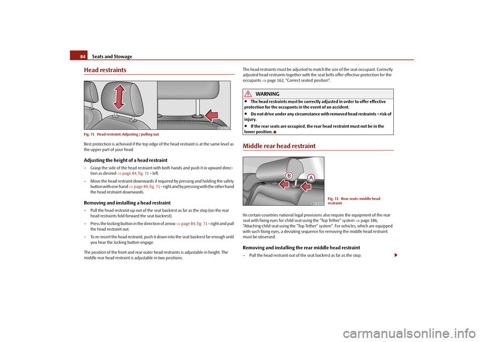
Head restraintsFig. 71 Head restraint: Adjusting / pulling outBest protection is achieved if the top edge of the head restraint is at the same level as
the upper part of your head.Adjusting the height of a head restraint– Grasp the side of the head restraint with both hands and push it in upward direc- tion as desired page 84, fig. 71 - left.
– Move the head restraint downwards if required by pressing and holding the safety button with one hand page 84, fig. 71 - right and by pressing with the other hand
the head restraint downwards.Removing and installing a head restraint– Pull the head restraint up out of the seat backrest as far as the stop (on the rear
head restraints fold forward the seat backrest).
– Press the locking button in the direction of arrow page 84, fig. 71 - right and pull
the head restraint out.
– To re-insert the head restraint, push it down into the seat backrest far enough until you hear the locking button engage.
The position of the front and rear outer head restraints is adjustable in height. The
middle rear head restraint is adjustable in two positions. The head restraints must be adjusted to ma
tch the size of the seat occupant. Correctly
adjusted head restraints together with the seat belts offer effective protection for the
occupants page 162, “Correct seated position”.
WARNING
The head restraints must be correctly adjusted in order to offer effective
protection for the occupants in the event of an accident.
Do not drive under any circumstance with removed head restraints - risk of
injury.
If the rear seats are occupied, the rear head restraint must not be in the
lower position.
Middle rear head restraintIIn certain countries national legal provisions also require the equipment of the rear
seat with fixing eyes for child seat using the “Top Tether” system page 186,
“Attaching child seat using the “Top Tether” system”. For vehicles, which are equipped
with such fixing eyes, a de viating sequence for removing the middle head restraint
must be observed.Removing and installing the rear middle head restraint– Pull the head restraint out of the seat backrest as far as the stop.
Fig. 72 Rear seats: middle head
restraint
s3fg.2.book Page 84 Friday, April 30, 2010 12:17 PM
Page 86 of 287
Seats and Stowage85
Using the system
Safety
Driving Tips
General Maintenance
Breakdown assistance
Technical Data
– Press the locking button in the direction of arrow
fig. 72 , press simultane-
ously the locking button into the opening using a flat screwdriver with a width
of maximum 5 mm and pull out the head restraint.
– To re-insert the head restraint, push it down into the seat backrest far enough until you hear the locking button engage.
WARNING
The head restraints must be correctly adjusted in order to offer effective
protection for the occupants in the event of an accident.
Do not drive under any circumstance with removed head restraints - risk of
injury.
If the rear seats are occupied, the rear head restraint must not be in the
lower position.
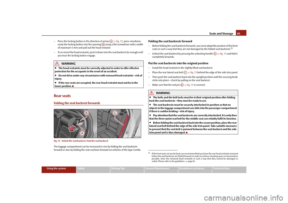
Rear seatsFolding the seat backrest forwardsFig. 73 Unlock the seat back rest / lock the seat backrestThe luggage compartment can be increased in size by folding the seat backrests
forward or also by folding the seat cushions forward on vehicles of the type Combi.
Folding the seat backrests forward– Before folding the seat backrests forwards, you must adapt the position of the front
seats in such a way that they are not damaged by the folded seat backrests.
9)
– Unlock the seat backrest by pressing the unlocking handle fig. 73 and fold it
completely forwards.Put the seat backrests into the original position– Install the head restraint in the slightly lifted seat backrest.
– Place the rear lateral seat belt fig. 73 behind the edge of the side trim panel.
– Then push the seat backrest back into th e upright position until the securing knob
clicks into place - check by pulling on the seat backrest.
– Make sure that the red pin fig. 73 is covered.
WARNING
The belts and the belt locks must be in their original position after folding
back the seat backrests - th ey must be ready to use.
The seat backrests must be securely interlocked in position so that no
objects in the luggage compartment can slide into the passenger compartment
if there is sudden braking - risk of injury.
Pay attention that the seat backrests are correctly interlocked. It is only then
that the three-point seat belt for the middle seat can reliably fulfil its function.
Before folding the seat backrest back into the secure position, place the rear
lateral seat belt behind the edge of the si de trim panel. Take suitable measures
to prevent that the seat belt is jammed between the seat backrest and the side
trim panel and is thus damaged.
AA
AB
9)If the front seats are too far back, we recommend that you have the rear head restraints removed
before the seat backrests are folded forward, in order to achieve a loading space as horizontal as
possible. Store the removed head restraints in such a way that they cannot be damaged or
soiled. Please refer to the guidelines page 87.
AA
AC
AB
s3fg.2.book Page 85 Friday, April 30, 2010 12:17 PM
Page 87 of 287
Seats and Stowage
86
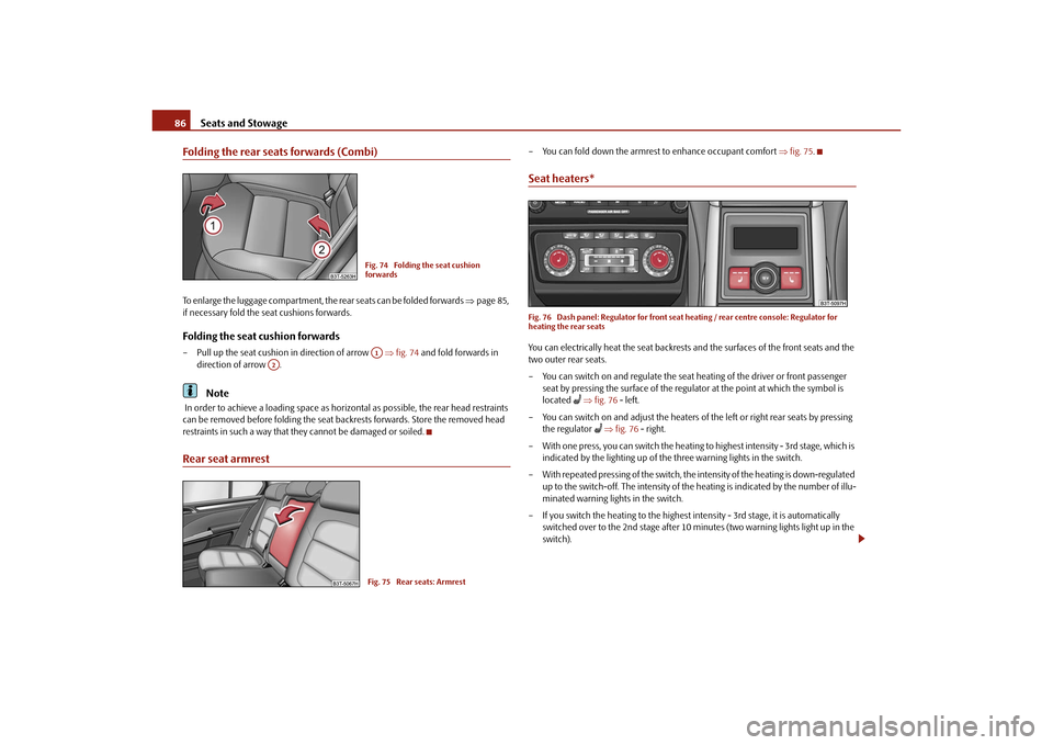
Folding the rear seats forwards (Combi)To enlarge the luggage compartment, the rear seats can be folded forwards page 85,
if necessary fold the seat cushions forwards.Folding the seat cushion forwards– Pull up the seat cushion in direction of arrow fig. 74 and fold forwards in
direction of arrow .
Note
In order to achieve a loading space as horizo ntal as possible, the rear head restraints
can be removed before folding the seat backrests forwards. Store the removed head
restraints in such a way that th ey cannot be damaged or soiled.Rear seat armrest
– You can fold down the armrest to enhance occupant comfort fig. 75 .Seat heaters*Fig. 76 Dash panel: Regulator for front seat heating / rear centre console: Regulator for
heating the rear seatsYou can electrically heat the seat backrests and the surfaces of the front seats and the
two outer rear seats.
– You can switch on and regulate the seat heating of the driver or front passenger
seat by pressing the surface of the regulator at the point at which the symbol is
located
fig. 76 - left.
– You can switch on and adjust the heaters of the left or right rear seats by pressing the regulator
fig. 76 - right.
– With one press, you can switch the heating to highest intensity - 3rd stage, which is
indicated by the lighting up of the three warning lights in the switch.
– With repeated pressing of the switch, the intensity of the heating is down-regulated up to the switch-off. The intensity of the heating is indicated by the number of illu-
minated warning lights in the switch.
– If you switch the heating to the highest intensity - 3rd stage, it is automatically switched over to the 2nd stage after 10 mi nutes (two warning lights light up in the
switch).
Fig. 74 Folding the seat cushion
forwardsA1
A2
Fig. 75 Rear seats: Armrest
s3fg.2.book Page 86 Friday, April 30, 2010 12:17 PM
Page 91 of 287

Seats and Stowage
90
Fixing floor covering of the luggage compartmentFig. 81 Luggage compartment: Fixing of the fl oor covering / luggage compartment: Fixing of
the floor covering (Combi)A loop fig. 81 left is located on the floor covering of the luggage compartment and
a hook fig. 81 right is located on the underside of the floor covering. When handling
the spare wheel*, you can raise the floor covering and fix it on a hook at the luggage
compartment cover.Luggage net*The luggage net is designed for the tranportation of lighter objects.
WARNING
In the storage net you must only stow objects (up to a total weight of 1.5 kg).
Heavy objects are not secured sufficiently - risk of injury!
No objects with sharp edges should be stowed in the luggage net, because
they can damage the luggage net.
Luggage compartment cover
You can use the luggage compartment cover behind the head
restraints for storing light and soft items.The luggage compartment cover can be remo ved as required if one must transport
bulky goods.
– Unhook the support straps fig. 83.
– Place the cover in th e horizontal position.
– Pull the cover out of the holder horizontally to the rear.
– Install again by pushing the luggage compartment cover forwards into the holder and hanging the support straps on the boot lid.
You can stow the removed luggage compartmen t cover behind the rear seat backrest.
WARNING
No objects should be placed on the luggage compartment cover, the vehicle
occupants could be endangered if th ere is sudden braking or the vehicle
collides with something.
Fig. 82 Luggage compartment: Luggage
net
WARNING (continued)
Fig. 83 Removing the luggage compart-
ment cover
A1
A2
A2
A1
s3fg.2.book Page 90 Friday, April 30, 2010 12:17 PM
Page 92 of 287

Seats and Stowage91
Using the system
Safety
Driving Tips
General Maintenance
Breakdown assistance
Technical Data
Caution
Please ensure that the heating elements of the rear window heater are not damaged
as a result of objects placed in this area.
Note
Opening the tailgate also lifts up the luggage compartment cover.Foldable luggage compartment cover (Combi)Fig. 84 Luggage compartment: foldable lugga ge compartment cover / removing foldable
luggage compartment coverPulling out– Pull the foldable luggage compartment cover as far as the stop into the secured
position fig. 84 .Folding– Press the cover in the handle area in direction of arrow fig. 84 , the cover rolls
up automatically into position . The cove r is fully rolled up by pressing once
again.Removing– The fully folded luggage compartment cover can be removed to transport bulky goods by pressing on the side of the cross rod in direction of arrow fig. 84
and taking it out by moving it in direction of arrow .
WARNING
No objects should be placed on the luggage compartment cover.Automatic foldable luggage compartment cover* (Combi)
The automatic rolling up of the fo ldable luggage compartment cover
enables an easier entry in to the luggage compartment.– Open the boot lid. The foldable luggage compartment cover rolls up automatically
in the position page 91, fig. 84 .
– The cover rolls up fully by pressing the cover in the handle area in direction of
arrow .
When the boot lid is opened quickly, the automatic rolling up of the foldable luggage
compartment cover is blocked for a delay time of approx. 2 seconds.
The function of the automatic rolling up of the foldable luggage compartment cover
can be activated/deactivated in the information display* in the menu:
SETUP
Autom. blindWARNING
No objects should be placed on the luggage compartment cover.
A2
A3
A1
A4
A5
A1
A3
s3fg.2.book Page 91 Friday, April 30, 2010 12:17 PM
Page 93 of 287
Seats and Stowage
92
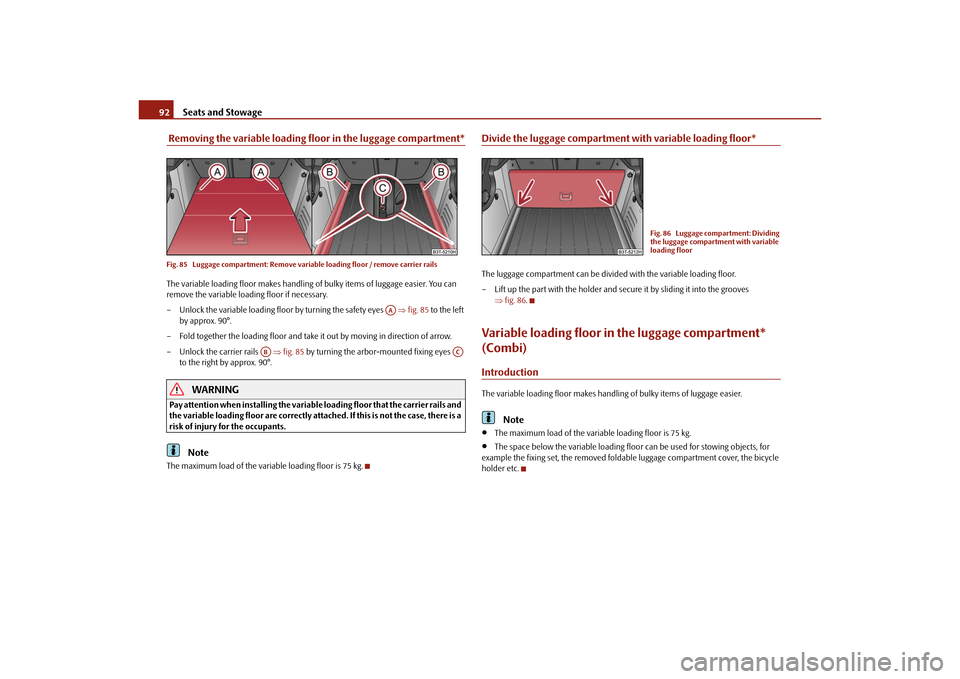
Removing the variable loading floor in the luggage compartment*Fig. 85 Luggage compartment: Remove variab le loading floor / remove carrier railsThe variable loading floor makes handling of bulky items of luggage easier. You can
remove the variable loading floor if necessary.
– Unlock the variable loading floor by turning the safety eyes fig. 85 to the left
by approx. 90°.
– Fold together the loading floor and take it out by moving in direction of arrow.
– Unlock the carrier rails fig. 85 by turning the arbor-mounted fixing eyes
to the right by approx. 90°.
WARNING
Pay attention when installing the variable loading floor that the carrier rails and
the variable loading floor are correctly atta ched. If this is not the case, there is a
risk of injury for the occupants.
Note
The maximum load of the variable loading floor is 75 kg.
Divide the luggage compartment with variable loading floor*The luggage compartment can be divided with the variable loading floor.
– Lift up the part with the holder and se cure it by sliding it into the grooves
fig. 86 .Variable loading floor in the luggage compartment*
(Combi)IntroductionThe variable loading floor makes handling of bulky items of luggage easier.
Note
The maximum load of the variable loading floor is 75 kg.
The space below the variable loading floo r can be used for stowing objects, for
example the fixing set, the removed foldab le luggage compartment cover, the bicycle
holder etc.
AA
AB
AC
Fig. 86 Luggage compartment: Dividing
the luggage compartment with variable
loading floor
s3fg.2.book Page 92 Friday, April 30, 2010 12:17 PM
Page 95 of 287
Seats and Stowage
94
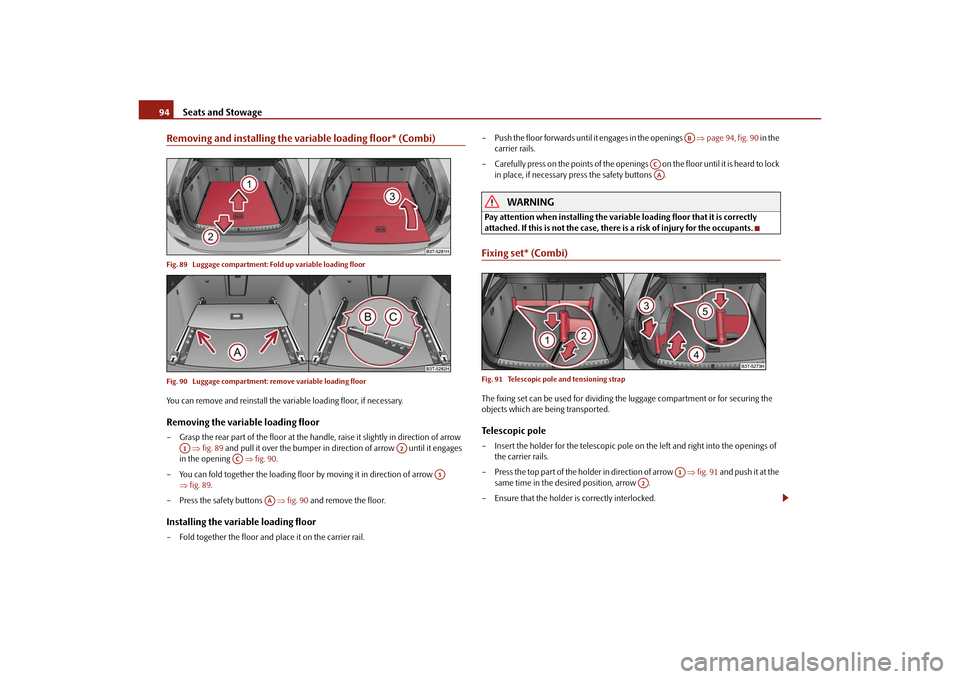
Removing and installing the var iable loading floor* (Combi)Fig. 89 Luggage compartment: Fold up variable loading floor
Fig. 90 Luggage compartment: remove variable loading floorYou can remove and reinstall the variable loading floor, if necessary.Removing the variable loading floor– Grasp the rear part of the floor at the handle, raise it slightly in direction of arrow
fig. 89 and pull it over the bumper in direction of arrow until it engages
in the opening fig. 90 .
– You can fold together the loading floor by moving it in direction of arrow
fig. 89 .
– Press the safety buttons fig. 90 and remove the floor.Installing the variable loading floor– Fold together the floor and place it on the carrier rail. – Push the floor forwards until it engages in the openings
page 94, fig. 90 in the
carrier rails.
– Carefully press on the points of the openings on the f loor unti l it i s hea rd to l ock
in place, if necessary press the safety buttons .
WARNING
Pay attention when installing the variable loading floor that it is correctly
attached. If this is not the case, there is a risk of injury for the occupants.Fixing set* (Combi)Fig. 91 Telescopic pole and tensioning strapThe fixing set can be used for dividing the luggage comp artment or for securing the
objects which are being transported.Telescopic pole– Insert the holder for the telescopic pole on the left and right into the openings of the carrier rails.
– Press the top part of the holder in direction of arrow fig. 91 and push it at the
same time in the desired position, arrow .
– Ensure that the holder is correctly interlocked.
A1
A2
AC
A3
AA
AB
ACAA
A1
A2
s3fg.2.book Page 94 Friday, April 30, 2010 12:17 PM
Page 97 of 287
Seats and Stowage
96
If you wish to use the entire luggage co mpartment, you can remove the foldable
luggage compartment cover page 91, fig. 84 .
WARNING
First check for yourself that the cross road is inserted into the mounts in the
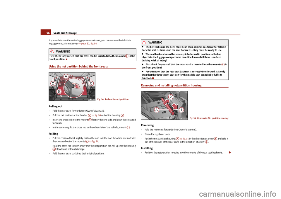
front position!Using the net partition behind the front seatsPulling out– Fold the rear seats forwards (see Owner's Manual).
– Pull the net partiton at the bracket fig. 94 out of the housing .
– Insert the cross rod into the mount first on the one side and push the cross rod forwards.
– In the same way, fix the cross rod to the other side of the vehicle, mount .Folding– Pull the cross rod back slightly, first on th e one side then on the other side and take
the cross rod out of the mounts fig. 94 .
– Hold the cross rod in such a way that the net partition can roll up into the housing
slowly and without damage.
– Fold the rear seats back into their original position.
WARNING
The belt locks and the belts must be in their original position after folding
back the seat cushions and the seat backrests - they must be ready to use.
The seat backrests must be securely interlocked in position so that no
objects in the luggage compartment can slide forwards if there is sudden
braking - risk of injury!
First check for yourself that the cross road is inserted into the mounts in
the front position!
Pay attention that the rear seat backrest is correctly interlocked. It is only
then that the three-point seat belt for the middle seat can reliably fulfil its
function.
Removing and installing net partition housingRemoving– Fold the rear seats forwards (see Owner's Manual).
– Open the right rear door.
– Push the net partition housing fig. 95 in the direction of arrow and take it
out of the mount of the rear seats in the direction of arrow .Installing– Position the net partition housing into the mounts of the rear seat backrests.
AC
Fig. 94 Pull out the net partition
AA
AB
AC
AC
AC
AB
AC
Fig. 95 Rear seats: Net partition housing
AA
A1
A2
s3fg.2.book Page 96 Friday, April 30, 2010 12:17 PM
Page 100 of 287

Seats and Stowage99
Using the system
Safety
Driving Tips
General Maintenance
Breakdown assistance
Technical Data
Note holderThe note holder is designed e.g. for attaching a car park ticket in parking areas.
The attached note has to always be removed before starting off in order not to restrict
the driver's vision.AshtrayFront ashtray*Removing ashtray insert– Open the ashtray page 102, fig. 106 .
– Grasp the ashtray insert at the point fig. 100 and take it out in direction of
arrow.
Insert ashtray insert– Insert the ashtray vertically downwards.
WARNING
Never lay flammable objects in the ashtray basin - risk of fire!Rear ashtray*Removing ashtray insert– Open the ashtray page 105, fig. 113 .
– Grasp the insert at the points marked with the arrows fig. 101 and take it out.Insert ashtray insert– Insert the ashtray insert into the mount and press it in.
WARNING
Never lay flammable objects in the ashtray basin - risk of fire!
Fig. 99 Windscreen: Note holderFig. 100 Centre console: Front ashtray
AA
Fig. 101 Centre console: Rear ashtray
s3fg.2.book Page 99 Friday, April 30, 2010 12:17 PM
Page 101 of 287

Seats and Stowage
100
Cigarette lighter*, power socketsCigarette lighter
You can also use the socket on the ci garette lighter for other electrical
appliances.Using the cigarette lighter– Press the button of the lighter fig. 101 or page 99, fig. 100.
– Wait until the button jumps forward.
– Remove the cigarette lighter immediately and use it.
– Insert the cigarette lighter again into the socket.Using the socket– Remove the cigarette lighter or the cover of the power socket.
– Connect the plug of the electrical appliance to the socket.
The 12 volt power socket can also be used to supply power to additional electrical
accessories with a power uptake up to 120 watts.
WARNING
Take care when using the cigarette ligh ter! Not paying proper attention or
incorrect use the cigarette lighter in an uncontrolled manner may result in
burns.
The cigarette lighter and the power socket also operates when the ignition is
switched off or the ignition key withdrawn. You should therefore never leave
children unattended in the vehicle.Caution
Always use matching plugs to avoid damagi ng the power socket.
Note
Connecting electrical components when the engine is not running will drain
the battery of the vehicle - risk of battery draining!
Further information page 234.
Power socket in the luggage compartmentFig. 102 Luggage compartment: Power socket / luggage compartment: Power socket (Combi)– Open the cover of the power socket fig. 102 .
– Connect the plug of the electrical appliance to the socket.
You can only use the power socket for the co nnection of approved electrical accesso-
ries with a power uptake up to 120 watts. The vehicle battery will be discharged in the
process if the engine is stationary.
The same remarks apply here as for page 100.
Further information page 234.Storage compartmentsOverviewYou will find the following storag e facilities in your vehicle:
AA
AB
s3fg.2.book Page 100 Friday, April 30, 2010 12:17 PM