lock SKODA SUPERB 2010 Owner´s Manual
[x] Cancel search | Manufacturer: SKODA, Model Year: 2010, Model line: SUPERB, Model: SKODA SUPERB 2010Pages: 252, PDF Size: 16.33 MB
Page 219 of 252

›Press any button on the remote control key.›Unlock the door with the key in the lock cylinder within 1 minute of pressing
the button.
Replace the battery in the remote control of the auxiliary heater
(parking heater)
Fig. 191
Radio remote control: Battery
cover
Read and observe on page 215 first.
The battery is located under a cover on the back of the radio remote con-
trol » Fig. 191 .
›
Insert a flat, blunt object, such as a coin, into the gap of the battery cover.
›
Turn the cover against the direction of the arrow up to the mark to open the
cover.
›
Replace the battery.
›
Return the battery cover.
›
Turn the cover in the direction of the arrow up to the initial marking, engage.
Emergency unlocking/locking
Introduction
This chapter contains information on the following subjects:
Unlocking/locking the driver's door
216
Locking the door without a locking cylinder
217
Unlocking the boot lid
217
Selector lever-emergency unlocking
217Unlocking/locking the driver's doorFig. 192
Handle on the driver's door: cov-
ered key cylinder
The driver's door can be unlocked or locked in an emergency.
›
Pull on the door handle and hold it pulled.
›
Insert the vehicle key into the slot on the underside of the cover in the re-
gion of the arrow » Fig. 192.
›
Fold the cover upwards.
›
Release the door handle.
›
Insert the remote control key into the lock cylinder and unlock or lock the ve-
hicle.
›
For vehicles with LHD insert the remote control key with the buttons facing
up into the lock cylinder and unlock or lock the vehicle.
›
For vehicles with RHD insert the remote control key directed with buttons
down into the lock cylinder and unlock or lock the vehicle.
Pull on the door handle and install the cover to the original location.
CAUTION
Make sure you do not damage the paint when performing an emergency lock-
ing/unlocking.216Do-it-yourself
Page 220 of 252
Locking the door without a locking cylinderFig. 193
Left rear door: Emergency lock-
ing
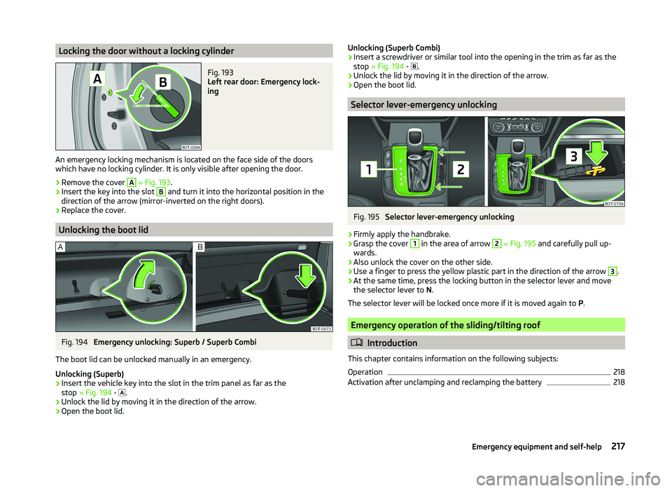
An emergency locking mechanism is located on the face side of the doors
which have no locking cylinder. It is only visible after opening the door.
›
Remove the cover
A
» Fig. 193 .
›
Insert the key into the slot
B
and turn it into the horizontal position in the
direction of the arrow (mirror-inverted on the right doors).
›
Replace the cover.
Unlocking the boot lid
Fig. 194
Emergency unlocking: Superb / Superb Combi
The boot lid can be unlocked manually in an emergency.
Unlocking (Superb)
›
Insert the vehicle key into the slot in the trim panel as far as the
stop » Fig. 194 -
.
›
Unlock the lid by moving it in the direction of the arrow.
›
Open the boot lid.
Unlocking (Superb Combi)›Insert a screwdriver or similar tool into the opening in the trim as far as the
stop » Fig. 194 -
.›
Unlock the lid by moving it in the direction of the arrow.
›
Open the boot lid.
Selector lever-emergency unlocking
Fig. 195
Selector lever-emergency unlocking
›
Firmly apply the handbrake.
›
Grasp the cover
1
in the area of arrow
2
» Fig. 195 and carefully pull up-
wards.
›
Also unlock the cover on the other side.
›
Use a finger to press the yellow plastic part in the direction of the arrow
3
.
›
At the same time, press the locking button in the selector lever and move the selector lever to N.
The selector lever will be locked once more if it is moved again to P.
Emergency operation of the sliding/tilting roof
Introduction
This chapter contains information on the following subjects:
Operation
218
Activation after unclamping and reclamping the battery
218217Emergency equipment and self-help
Page 222 of 252
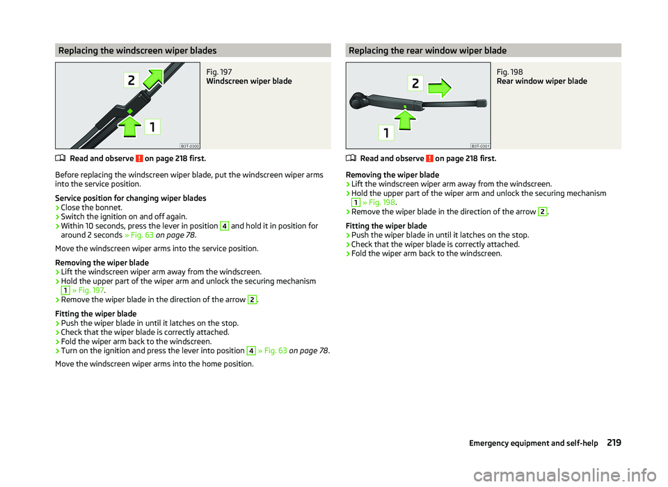
Replacing the windscreen wiper bladesFig. 197
Windscreen wiper blade
Read and observe on page 218 first.
Before replacing the windscreen wiper blade, put the windscreen wiper arms
into the service position.
Service position for changing wiper blades
›
Close the bonnet.
›
Switch the ignition on and off again.
›
Within 10 seconds, press the lever in position
4
and hold it in position for
around 2 seconds » Fig. 63 on page 78 .
Move the windscreen wiper arms into the service position.
Removing the wiper blade
›
Lift the windscreen wiper arm away from the windscreen.
›
Hold the upper part of the wiper arm and unlock the securing mechanism
1
» Fig. 197 .
›
Remove the wiper blade in the direction of the arrow
2
.
Fitting the wiper blade
›
Push the wiper blade in until it latches on the stop.
›
Check that the wiper blade is correctly attached.
›
Fold the wiper arm back to the windscreen.
›
Turn on the ignition and press the lever into position
4
» Fig. 63 on page 78 .
Move the windscreen wiper arms into the home position.
Replacing the rear window wiper bladeFig. 198
Rear window wiper blade
Read and observe on page 218 first.
Removing the wiper blade
›
Lift the windscreen wiper arm away from the windscreen.
›
Hold the upper part of the wiper arm and unlock the securing mechanism
1
» Fig. 198 .
›
Remove the wiper blade in the direction of the arrow
2
.
Fitting the wiper blade
›
Push the wiper blade in until it latches on the stop.
›
Check that the wiper blade is correctly attached.
›
Fold the wiper arm back to the windscreen.
219Emergency equipment and self-help
Page 224 of 252
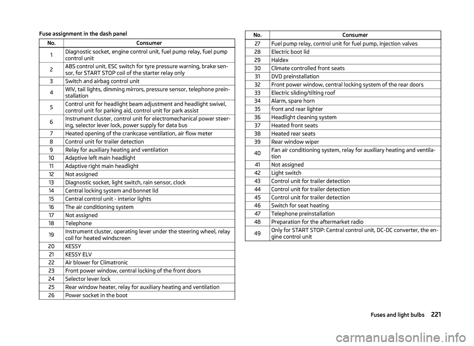
Fuse assignment in the dash panelNo.Consumer1Diagnostic socket, engine control unit, fuel pump relay, fuel pump
control unit2ABS control unit, ESC switch for tyre pressure warning, brake sen-
sor, for START STOP coil of the starter relay only3Switch and airbag control unit4WIV, tail lights, dimming mirrors, pressure sensor, telephone prein-
stallation5Control unit for headlight beam adjustment and headlight swivel,
control unit for parking aid, control unit for park assist6Instrument cluster, control unit for electromechanical power steer-
ing, selector lever lock, power supply for data bus7Heated opening of the crankcase ventilation, air flow meter8Control unit for trailer detection9Relay for auxiliary heating and ventilation10Adaptive left main headlight11Adaptive right main headlight12Not assigned13Diagnostic socket, light switch, rain sensor, clock14Central locking system and bonnet lid15Central control unit - interior lights16The air conditioning system17Not assigned18Telephone19Instrument cluster, operating lever under the steering wheel, relay
coil for heated windscreen20KESSY21KESSY ELV22Air blower for Climatronic23Front power window, central locking of the front doors24Selector lever lock25Rear window heater, relay for auxiliary heating and ventilation26Power socket in the bootNo.Consumer27Fuel pump relay, control unit for fuel pump, injection valves28Electric boot lid29Haldex30Climate controlled front seats31DVD preinstallation32Front power window, central locking system of the rear doors33Electric sliding/tilting roof34Alarm, spare horn35front and rear lighter36Headlight cleaning system37Heated front seats38Heated rear seats39Rear window wiper40Fan air conditioning system, relay for auxiliary heating and ventila-
tion41Not assigned42Light switch43Control unit for trailer detection44Control unit for trailer detection45Control unit for trailer detection46Switch for seat heating47Telephone preinstallation48Preparation for the aftermarket radio49Only for START STOP: Central control unit, DC-DC converter, the en-
gine control unit221Fuses and light bulbs
Page 225 of 252
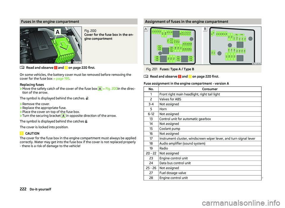
Fuses in the engine compartmentFig. 200
Cover for the fuse box in the en-
gine compartment
Read and observe and on page 220 first.
On some vehicles, the battery cover must be removed before removing the
cover for the fuse box » page 195.
Replacing fuses
›
Move the safety catch of the cover of the fuse box
A
» Fig. 200 in the direc-
tion of the arrow.
The symbol is displayed behind the catches. .
›
Remove the cover.
›
Replace the appropriate fuse.
›
Place the cover on top of the fuse box.
›
Turn the securing bracket
A
in opposite direction of the arrow.
The symbol is displayed behind the catches .
The cover is locked into position.
CAUTION
The cover for the fuse box in the engine compartment must always be applied
correctly. Water may get into the fuse box if the cover is not replaced properly
- there is a risk of damage to the vehicle!Assignment of fuses in the engine compartmentFig. 201
Fuses: Type A / Type B
Read and observe
and on page 220 first.
Fuse assignment in the engine compartment - version A
No.Consumer1Front right main headlight, right tail light2Valves for ABS3-4Not assigned5Horn6-12Not assigned13Control unit for automatic gearbox14Not assigned15Coolant pump16Not assigned17Instrument cluster, windscreen wiper lever, and turn signal lever18Audio amplifier (sound system)19Radio20 - 22Not assigned23Engine control unit24Data bus control unit25 - 26Not assigned27Fuel dosage valve28Engine control unit 222Do-it-yourself
Page 228 of 252
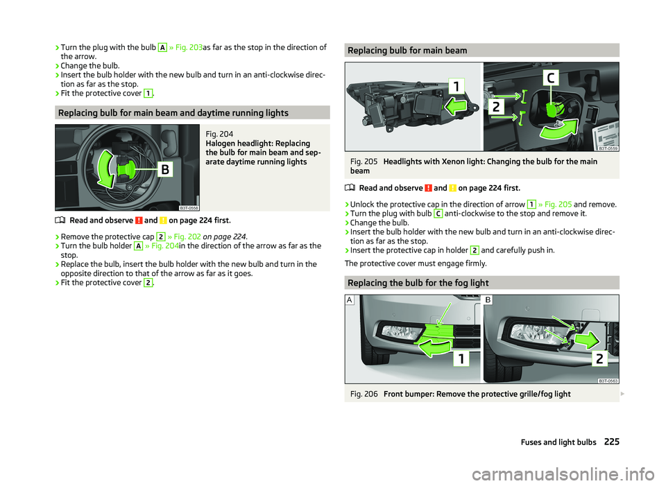
›Turn the plug with the bulb A
» Fig. 203 as far as the stop in the direction of
the arrow.›
Change the bulb.
›
Insert the bulb holder with the new bulb and turn in an anti-clockwise direc-
tion as far as the stop.
›
Fit the protective cover
1
.
Replacing bulb for main beam and daytime running lights
Fig. 204
Halogen headlight: Replacing
the bulb for main beam and sep-
arate daytime running lights
Read and observe and on page 224 first.
›
Remove the protective cap
2
» Fig. 202 on page 224 .
›
Turn the bulb holder
A
» Fig. 204 in the direction of the arrow as far as the
stop.
›
Replace the bulb, insert the bulb holder with the new bulb and turn in the
opposite direction to that of the arrow as far as it goes.
›
Fit the protective cover
2
.
Replacing bulb for main beamFig. 205
Headlights with Xenon light: Changing the bulb for the main
beam
Read and observe
and on page 224 first.
›
Unlock the protective cap in the direction of arrow
1
» Fig. 205 and remove.
›
Turn the plug with bulb
C
anti-clockwise to the stop and remove it.
›
Change the bulb.
›
Insert the bulb holder with the new bulb and turn in an anti-clockwise direc-
tion as far as the stop.
›
Insert the protective cap in holder
2
and carefully push in.
The protective cover must engage firmly.
Replacing the bulb for the fog light
Fig. 206
Front bumper: Remove the protective grille/fog light
225Fuses and light bulbs
Page 229 of 252
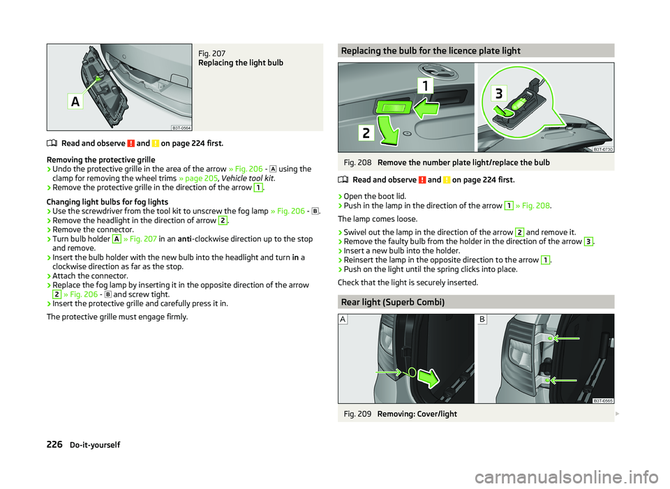
Fig. 207
Replacing the light bulb
Read and observe and on page 224 first.
Removing the protective grille
›
Undo the protective grille in the area of the arrow » Fig. 206 -
using the
clamp for removing the wheel trims » page 205, Vehicle tool kit .
›
Remove the protective grille in the direction of the arrow
1
.
Changing light bulbs for fog lights
›
Use the screwdriver from the tool kit to unscrew the fog lamp » Fig. 206 -
.
›
Remove the headlight in the direction of arrow
2
.
›
Remove the connector.
›
Turn bulb holder
A
» Fig. 207 in an anti-clockwise direction up to the stop
and remove.
›
Insert the bulb holder with the new bulb into the headlight and turn in a
clockwise direction as far as the stop.
›
Attach the connector.
›
Replace the fog lamp by inserting it in the opposite direction of the arrow
2
» Fig. 206 -
and screw tight.
›
Insert the protective grille and carefully press it in.
The protective grille must engage firmly.
Replacing the bulb for the licence plate lightFig. 208
Remove the number plate light/replace the bulb
Read and observe
and on page 224 first.
›
Open the boot lid.
›
Push in the lamp in the direction of the arrow
1
» Fig. 208 .
The lamp comes loose.
›
Swivel out the lamp in the direction of the arrow
2
and remove it.
›
Remove the faulty bulb from the holder in the direction of the arrow
3
.
›
Insert a new bulb into the holder.
›
Reinsert the lamp in the opposite direction to the arrow
1
.
›
Push on the light until the spring clicks into place.
Check that the light is securely inserted.
Rear light (Superb Combi)
Fig. 209
Removing: Cover/light
226Do-it-yourself
Page 230 of 252
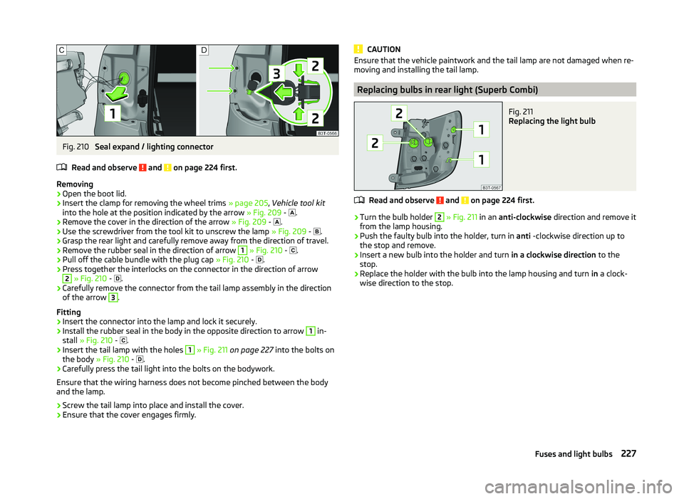
Fig. 210
Seal expand / lighting connector
Read and observe
and on page 224 first.
Removing
›
Open the boot lid.
›
Insert the clamp for removing the wheel trims » page 205, Vehicle tool kit
into the hole at the position indicated by the arrow » Fig. 209 -
.
›
Remove the cover in the direction of the arrow
» Fig. 209 -
.
›
Use the screwdriver from the tool kit to unscrew the lamp
» Fig. 209 -
.
›
Grasp the rear light and carefully remove away from the direction of travel.
›
Remove the rubber seal in the direction of arrow
1
» Fig. 210 -
.
›
Pull off the cable bundle with the plug cap
» Fig. 210 -
.
›
Press together the interlocks on the connector in the direction of arrow
2
» Fig. 210 -
.
›
Carefully remove the connector from the tail lamp assembly in the direction
of the arrow
3
.
Fitting
›
Insert the connector into the lamp and lock it securely.
›
Install the rubber seal in the body in the opposite direction to arrow
1
in-
stall » Fig. 210 -
.
›
Insert the tail lamp with the holes
1
» Fig. 211 on page 227 into the bolts on
the body » Fig. 210 -
.
›
Carefully press the tail light into the bolts on the bodywork.
Ensure that the wiring harness does not become pinched between the body
and the lamp.
›
Screw the tail lamp into place and install the cover.
›
Ensure that the cover engages firmly.
CAUTIONEnsure that the vehicle paintwork and the tail lamp are not damaged when re-
moving and installing the tail lamp.
Replacing bulbs in rear light (Superb Combi)
Fig. 211
Replacing the light bulb
Read and observe and on page 224 first.
›
Turn the bulb holder
2
» Fig. 211 in an anti-clockwise direction and remove it
from the lamp housing.
›
Push the faulty bulb into the holder, turn in anti -clockwise direction up to
the stop and remove.
›
Insert a new bulb into the holder and turn in a clockwise direction to the
stop.
›
Replace the holder with the bulb into the lamp housing and turn in a clock-
wise direction to the stop.
227Fuses and light bulbs
Page 231 of 252
Technical data
Technical data
Vehicle data
Introduction
This chapter contains information on the following subjects:
Vehicle identification data
228
Operating weight and payload
229
Measurement of fuel consumption and CO 2 emissions according to ECE
Regulations and EU Directives
229
Dimensions
230
Vehicle-specific information depending on engine type
231
Multi-purpose vehicles (AF)
235
The details given in the vehicle's technical documentation always take prece-
dence over the details in the Owner's Manual.
The listed performance values were determined without performance-reduc- ing equipment, e.g. air conditioning system.
Vehicle identification data
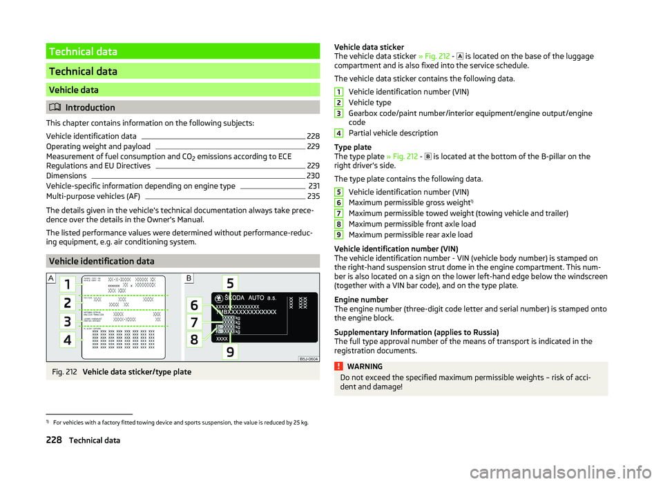
Fig. 212
Vehicle data sticker/type plate
Vehicle data sticker
The vehicle data sticker » Fig. 212 - is located on the base of the luggage
compartment and is also fixed into the service schedule.
The vehicle data sticker contains the following data. Vehicle identification number (VIN)
Vehicle type
Gearbox code/paint number/interior equipment/engine output/engine
code
Partial vehicle description
Type plate
The type plate » Fig. 212 -
is located at the bottom of the B-pillar on the
right driver's side.
The type plate contains the following data. Vehicle identification number (VIN)
Maximum permissible gross weight 1)
Maximum permissible towed weight (towing vehicle and trailer)
Maximum permissible front axle load
Maximum permissible rear axle load
Vehicle identification number (VIN)
The vehicle identification number - VIN (vehicle body number) is stamped on
the right-hand suspension strut dome in the engine compartment. This num- ber is also located on a sign on the lower left-hand edge below the windscreen
(together with a VIN bar code), and on the type plate.
Engine number
The engine number (three-digit code letter and serial number) is stamped onto
the engine block.
Supplementary Information (applies to Russia)
The full type approval number of the means of transport is indicated in the
registration documents.WARNINGDo not exceed the specified maximum permissible weights – risk of acci-
dent and damage!1234567891)
For vehicles with a factory fitted towing device and sports suspension, the value is reduced by 25 kg.
228Technical data
Page 239 of 252
Index
A
Abroad Driving abroad
153
Unleaded petrol153
ABS Operation
155
Warning light38
Accessories173
Adaptive headlights (AHL)70
Adjust Auxiliary heating (auxiliary heating and ventila- tion)
119
Head restraints83
Adjusting Belt height
15
Exterior mirrors80
Interior mirror79
Manual air conditioning114
Seats81, 82
Steering wheel10
Adjusting the seats9, 81
Adjustment Range of light
68
Aerial177
See windows179
AHL70
Warning light38
Airbag16
Deactivating21
Deactivating the front passenger airbag21
Deployment16
Front airbag17
Head airbag20
Indicator light40
Knee airbag18
Modifications and damage to the airbag system 175
Side airbag
19
Airbag system16
Air conditioning system110
Air outlets110
Climatronic115
Manual air conditioning system112
Air outlets110
Air recirculation Climatronic
117
Alarm Switching off
55
Triggering55
Anti-theft alarm system Activating/deactivating
56
Trailer172
Anti-theft wheel bolts208
Antilock brake system (ABS)155
Armrest Front
87
rear96
Rear87
Ashtray91
ASR Operation
155
warning light37
Assist systems154
ABS38, 155
ASR37, 155
Cruise Control System161
DSR155
EDL155
ESC37, 154
HBA155
HHC156
Park assist157
Parking aid156
START STOP162
Audio see radio / navigation system
4
Auto Check Control33
Automatic driving lamp control70
Automatic gearbox Selector lever-emergency unlocking217
Starting off and driving147
Tiptronic146
Using the selector lever145
Automatic gearbox modes145
Automatic load deactivation197
Automatic retractable cargo cover (Superb Combi))
101
Automatic transmission145
Kickdown147
Malfunction148
Selector lever lock146
AUX Installation in the storage compartment
92
Auxiliary heating (auxiliary heating and ventila- tion)
118
Adjust119
Radio remote control120
Switching on/off119
Avoiding damage to the vehicle Driving through water
152
Avoiding damage to your vehicle152
B
Ball head Check fitting
168
Fitting168
Ready position167
Removing169
Battery In the remote control key
215
Replace the remote control of the auxiliary heater (parking heater)
216
Belts12
Belt tensioners15
Bonnet Closing
187
Opening187
Warning light36
236Index