traction control SKODA SUPERB 2010 Owner´s Manual
[x] Cancel search | Manufacturer: SKODA, Model Year: 2010, Model line: SUPERB, Model: SKODA SUPERB 2010Pages: 252, PDF Size: 16.33 MB
Page 10 of 252
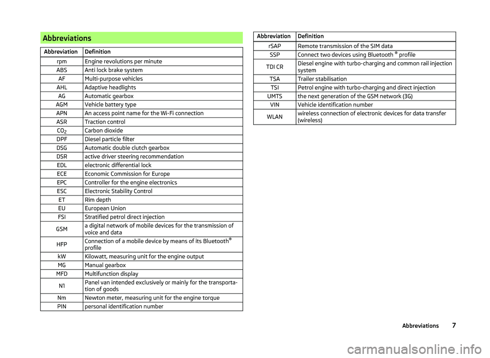
AbbreviationsAbbreviationDefinitionrpmEngine revolutions per minuteABSAnti lock brake systemAFMulti-purpose vehiclesAHLAdaptive headlightsAGAutomatic gearboxAGMVehicle battery typeAPNAn access point name for the Wi-Fi connectionASRTraction controlCO2Carbon dioxideDPFDiesel particle filterDSGAutomatic double clutch gearboxDSRactive driver steering recommendationEDLelectronic differential lockECEEconomic Commission for EuropeEPCController for the engine electronicsESCElectronic Stability ControlETRim depthEUEuropean UnionFSIStratified petrol direct injectionGSMa digital network of mobile devices for the transmission of
voice and dataHFPConnection of a mobile device by means of its Bluetooth ®
profilekWKilowatt, measuring unit for the engine outputMGManual gearboxMFDMultifunction displayN1Panel van intended exclusively or mainly for the transporta-
tion of goodsNmNewton meter, measuring unit for the engine torquePINpersonal identification numberAbbreviationDefinitionrSAPRemote transmission of the SIM dataSSPConnect two devices using Bluetooth ®
profileTDI CRDiesel engine with turbo-charging and common rail injection
systemTSATrailer stabilisationTSIPetrol engine with turbo-charging and direct injectionUMTSthe next generation of the GSM network (3G)VINVehicle identification numberWLANwireless connection of electronic devices for data transfer
(wireless)7Abbreviations
Page 32 of 252
Operation
Cockpit
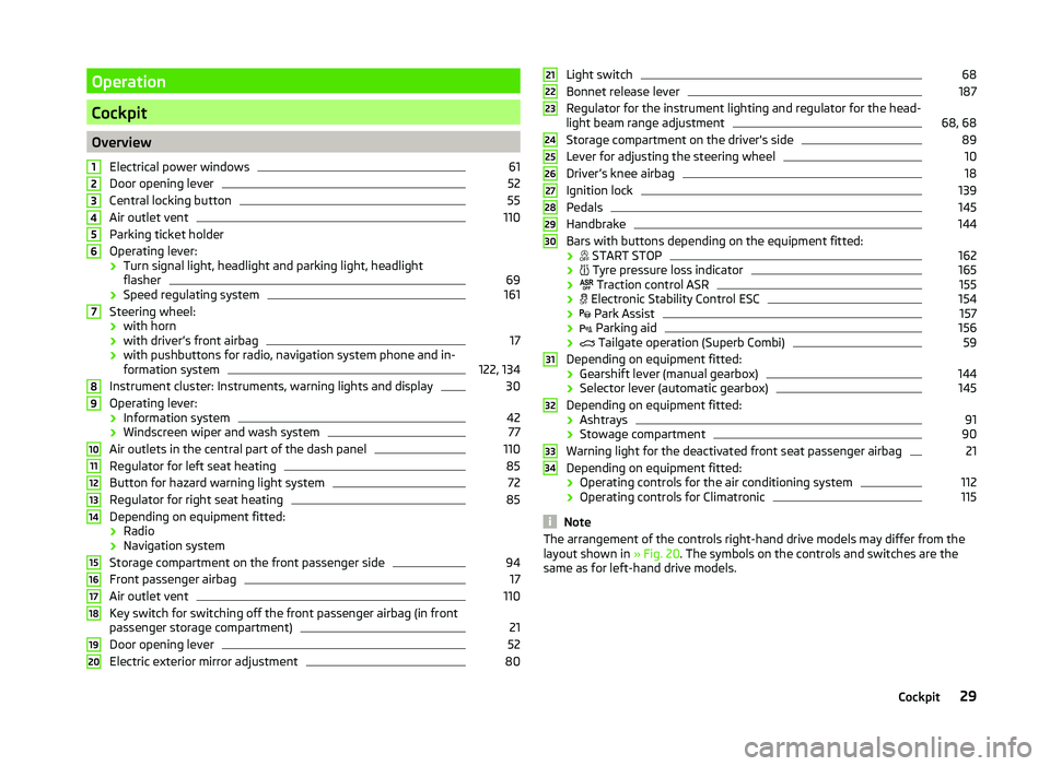
OverviewElectrical power windows
61
Door opening lever
52
Central locking button
55
Air outlet vent
110
Parking ticket holder
Operating lever: › Turn signal light, headlight and parking light, headlight
flasher
69
› Speed regulating system
161
Steering wheel:
› with horn
› with driver’s front airbag
17
› with pushbuttons for radio, navigation system phone and in-
formation system
122, 134
Instrument cluster: Instruments, warning lights and display
30
Operating lever:
› Information system
42
›Windscreen wiper and wash system
77
Air outlets in the central part of the dash panel
110
Regulator for left seat heating
85
Button for hazard warning light system
72
Regulator for right seat heating
85
Depending on equipment fitted:
› Radio
› Navigation system
Storage compartment on the front passenger side
94
Front passenger airbag
17
Air outlet vent
110
Key switch for switching off the front passenger airbag (in front
passenger storage compartment)
21
Door opening lever
52
Electric exterior mirror adjustment
801234567891011121314151617181920Light switch68
Bonnet release lever
187
Regulator for the instrument lighting and regulator for the head-
light beam range adjustment
68, 68
Storage compartment on the driver's side
89
Lever for adjusting the steering wheel
10
Driver’s knee airbag
18
Ignition lock
139
Pedals
145
Handbrake
144
Bars with buttons depending on the equipment fitted:
›
START STOP
162
›
Tyre pressure loss indicator
165
›
Traction control ASR
155
›
Electronic Stability Control ESC
154
›
Park Assist
157
›
Parking aid
156
›
Tailgate operation (Superb Combi)
59
Depending on equipment fitted:
› Gearshift lever (manual gearbox)
144
›Selector lever (automatic gearbox)
145
Depending on equipment fitted:
› Ashtrays
91
›Stowage compartment
90
Warning light for the deactivated front seat passenger airbag
21
Depending on equipment fitted:
› Operating controls for the air conditioning system
112
›
Operating controls for Climatronic
115
Note
The arrangement of the controls right-hand drive models may differ from the
layout shown in » Fig. 20. The symbols on the controls and switches are the
same as for left-hand drive models.212223242526272829303132333429Cockpit
Page 37 of 252
The following message is shown in the MAXI DOT display.Gearbox overheated. Stop! Owner's manual!
do not continue to drive! Stop the vehicle, switch off the engine, and wait
until the
icon goes out – risk of gearbox damage! You can continue your
journey as soon as the icon disappears.WARNINGIf you have to stop for technical reasons, then park the vehicle at a safe
distance from the traffic, switch off the engine and activate the hazard
warning light system » page 72. The warning triangle must be set up at
the prescribed distance - observe the national legal provisions when doing
so.
Note
■ If the MAXI DOT display shows warning messages, these messages must be
confirmed in order to access the main menu » page 42 .■
As long as the operational faults are not rectified, the symbols are always in-
dicated again. After they are displayed for the first time, the symbols continue
to be indicated without any extra messages for the driver.
Warning lights
Introduction
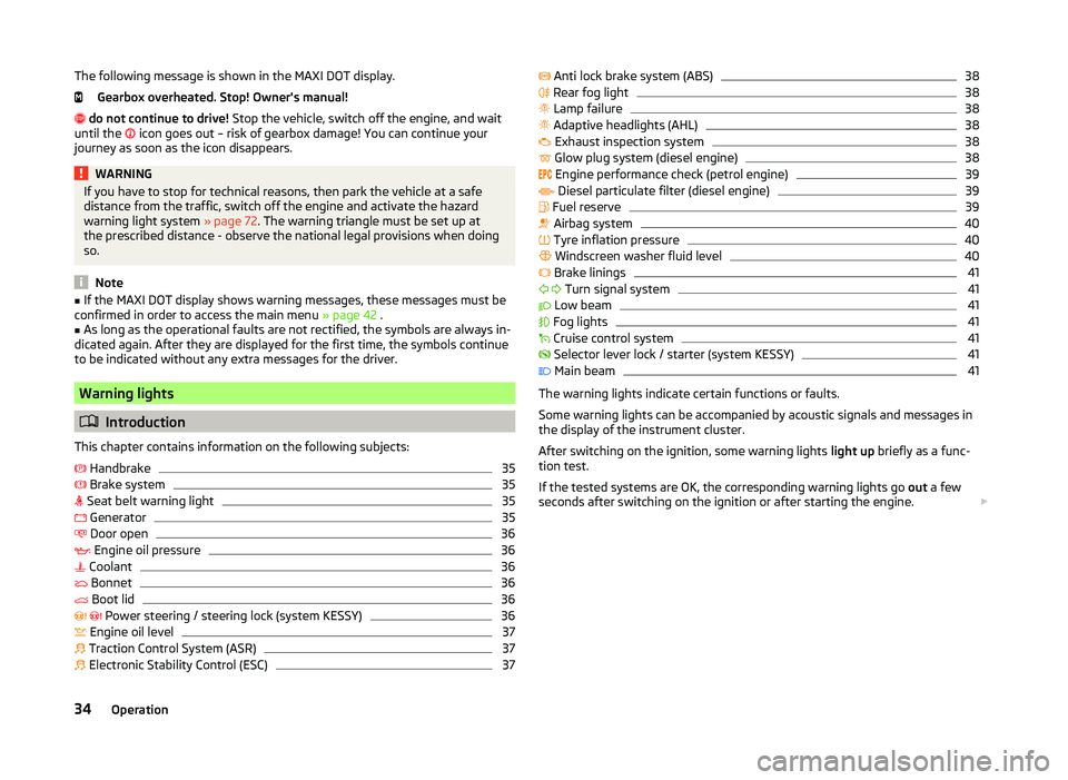
This chapter contains information on the following subjects:
Handbrake
35
Brake system
35
Seat belt warning light
35
Generator
35
Door open
36
Engine oil pressure
36
Coolant
36
Bonnet
36
Boot lid
36
Power steering / steering lock (system KESSY)
36
Engine oil level
37
Traction Control System (ASR)
37
Electronic Stability Control (ESC)
37 Anti lock brake system (ABS)38 Rear fog light38
Lamp failure
38
Adaptive headlights (AHL)
38
Exhaust inspection system
38
Glow plug system (diesel engine)
38
Engine performance check (petrol engine)
39
Diesel particulate filter (diesel engine)
39
Fuel reserve
39
Airbag system
40
Tyre inflation pressure
40
Windscreen washer fluid level
40
Brake linings
41
Turn signal system
41
Low beam
41
Fog lights
41
Cruise control system
41
Selector lever lock / starter (system KESSY)
41
Main beam
41
The warning lights indicate certain functions or faults.
Some warning lights can be accompanied by acoustic signals and messages in
the display of the instrument cluster.
After switching on the ignition, some warning lights light up briefly as a func-
tion test.
If the tested systems are OK, the corresponding warning lights go out a few
seconds after switching on the ignition or after starting the engine.
34Operation
Page 40 of 252
If the warning light or illuminates again, then immediately obtain help
from an authorised dealer.
Steering lock (KESSY system)
A long as the warning light
flashes , the steering lock cannot be released.
If the warning light
flashes , a signal tone sounds, and the following mes-
sage appears in the MAXI DOT- display Steering column lock. Workshop! ap-
pears the electrical steering lock is faulty. Seek assistance from a specialist ga-
rage immediately.
If the warning light
flashes , a beep will sound and a message Steering lock:
defective appears in theMAXI DOT display, this indicates that the electric
steering lock is broken. Park the vehicle, do not continue your journey!
. Af-
ter switching off the ignition, it is then no longer possible to lock the steering,
to activate the electrical components (e.g. radio, navigation system), to switch
on the ignition again and to start the engine. Seek help from a specialist ga-
rage.
Note
The warning light illuminates after the ignition is switched on if the vehi-
cle's battery has been disconnected and reconnected. If the warning light
does not go out after moving a short distance, this means there is an error in
the system. Seek assistance from a specialist garage immediately.
Engine oil level
Read and observe
on page 35 first.
The warning light illuminates (oil quantity too low)
The following message is shown in the MAXI DOT display.
Check oil level!
› Stop the vehicle, switch off the engine, and check the engine oil lev-
el » page 190 .
The warning light will go out if the bonnet is left open for more than 30 sec-
onds. If no engine oil has been replenished, the warning light will come on
again after driving about 100 km.
The warning light flashes (engine oil level sensor faulty)
The following message is shown in the MAXI DOT display.
Oil sensor: Workshop!
If the engine oil level sensor is faulty, the warning light flashes several
times and an audible signal sounds when the ignition is turned on.
Seek assistance from a specialist garage immediately.
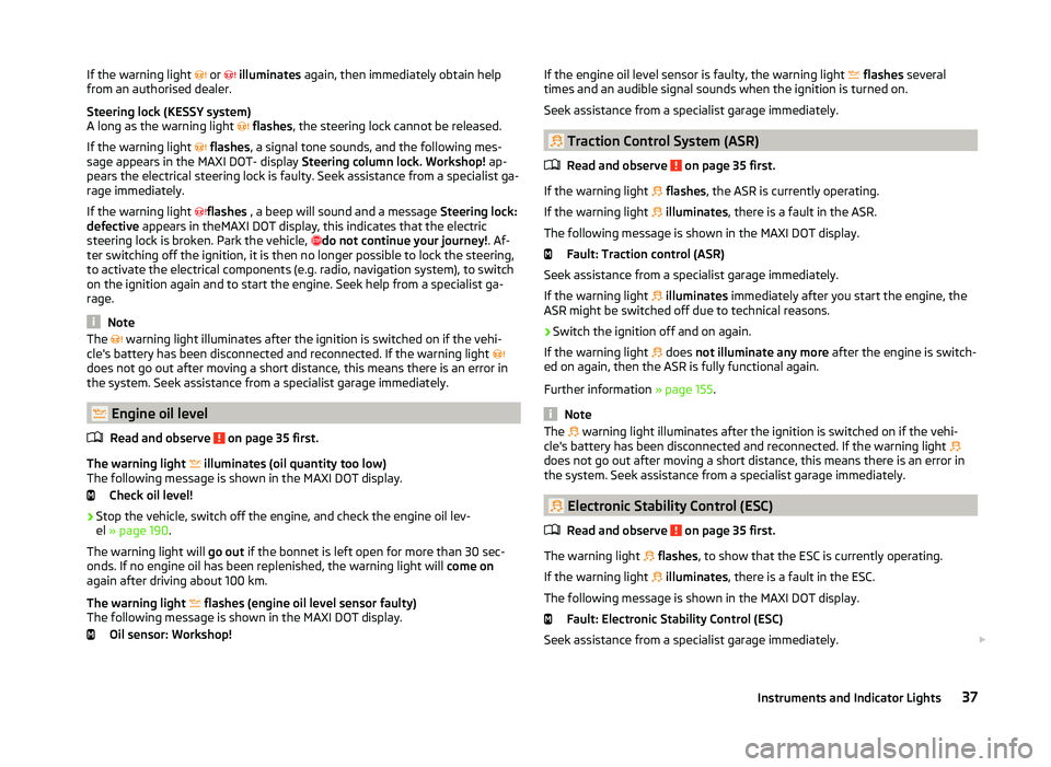
Traction Control System (ASR)
Read and observe
on page 35 first.
If the warning light
flashes , the ASR is currently operating.
If the warning light
illuminates , there is a fault in the ASR.
The following message is shown in the MAXI DOT display. Fault: Traction control (ASR)
Seek assistance from a specialist garage immediately.
If the warning light
illuminates immediately after you start the engine, the
ASR might be switched off due to technical reasons.
›
Switch the ignition off and on again.
If the warning light does
not illuminate any more after the engine is switch-
ed on again, then the ASR is fully functional again.
Further information » page 155.
Note
The warning light illuminates after the ignition is switched on if the vehi-
cle's battery has been disconnected and reconnected. If the warning light
does not go out after moving a short distance, this means there is an error in
the system. Seek assistance from a specialist garage immediately.
Electronic Stability Control (ESC)
Read and observe
on page 35 first.
The warning light
flashes , to show that the ESC is currently operating.
If the warning light
illuminates , there is a fault in the ESC.
The following message is shown in the MAXI DOT display. Fault: Electronic Stability Control (ESC)
Seek assistance from a specialist garage immediately.
37Instruments and Indicator Lights
Page 157 of 252
Assist systems
Brake assist systems
Introduction
This chapter contains information on the following subjects:
Electronic Stability Control (ESC)
154
Antilock brake system (ABS)
155
Traction Control System (ASR)
155
Electronic Differential Lock (EDL)
155
Driver Steering Recommendation (DSR)
155
Hydraulic Brake Assist (HBA)
155
Hill Hold Control (HHC)
156WARNING■ A lack of fuel can cause irregular engine running or cause the engine to
shut down. The brake assist systems would then fail to function – risk of
accident!■
Adjust the speed and driving style to the current visibility, weather, road
and traffic conditions. The increased safety provided by the brake assist
systems must not tempt you to take safety risks – risk of accident!
■
In the event of an ABS fault, visit a specialist garage immediately. Adjust
your style of driving according to the damage to the ABS, as you will not
know the exact extent of the damage or the extent to which this is limiting the braking efficiency.
CAUTION
■ All four wheels must be fitted with the same tyres approved by the manufac-
turer to ensure the brake assist systems operate correctly.■
Changes to the vehicle (e.g. to the engine, brakes, chassis) can influence the
functionality of the brake assist systems » page 173, Services, modifications
and technical alterations .
■
If a fault occurs in the ABS system, the ESC, ASR and EDL will also not work.
An ABS fault is indicated with the warning light
» page 38 .
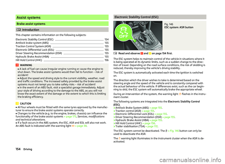
Electronic Stability Control (ESC)Fig. 146
ESC system: ASR button
Read and observe and on page 154 first.
The ESC system helps to maintain control of the vehicle in situations where it
is being operated at its dynamic limits, such as a sudden change to the direc-
tion of travel. Depending on the road surface conditions, the risk of skidding is
reduced, thereby improving the vehicle's driving stability .
The ESC system is automatically activated each time the ignition is switched on.
The direction which the driver wishes to take is determined based on the
steering angle and the speed of the vehicle and is constantly compared with
the actual behaviour of the vehicle. If differences exist, such as the car begin-
ning to skid, the ESC system will automatically brake the appropriate wheel.
During an intervention of the system, the warning light flashes in the instru-
ment cluster.
The following systems are integrated into the Electronic Stability Control
(ESC) .
› Antilock Brake System (ABS)
» page 155.
› Traction control (ASR)
» page 155.
› Electronic Differential Lock (EDL)
» page 155.
› Driver Steering Recommendation (DSR)
» page 155.
› Hydraulic Brake Assist (HBA)
» page 155.
› Hill Hold Control (HHC)
» page 156.
› Trailer stabilisation (TSA)
» page 172.
The ESC system cannot be deactivated. The
» Fig. 146 button can only be
used to deactivate the ASR.
The warning light illuminates in the instrument cluster when the ASR is de-
activated.
154Driving
Page 158 of 252
Antilock brake system (ABS)Read and observe
and on page 154 first.
ABS prevents the wheels locking when braking. Thereby, it helps the driver to
maintain control of the vehicle.
The intervention of the ABS is noticeable from the pulsating movements of
the brake pedal which is accompanied by noises.
When the ABS system is active, do not brake periodically or reduce the pres-
sure on the brake pedal.
Traction Control System (ASR)
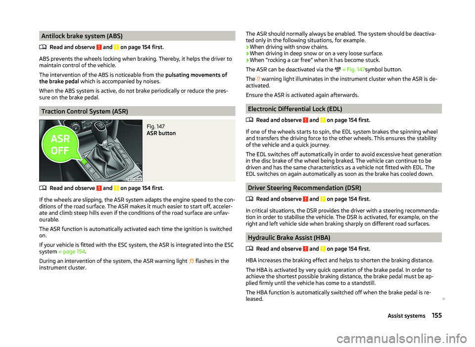
Fig. 147
ASR button
Read and observe and on page 154 first.
If the wheels are slipping, the ASR system adapts the engine speed to the con- ditions of the road surface. The ASR makes it much easier to start off, acceler-
ate and climb steep hills even if the conditions of the road surface are unfav-
ourable.
The ASR function is automatically activated each time the ignition is switched
on.
If your vehicle is fitted with the ESC system, the ASR is integrated into the ESC
system » page 154 .
During an intervention of the system, the ASR warning light flashes in the
instrument cluster.
The ASR should normally always be enabled. The system should be deactiva-
ted only in the following situations, for example.
› When driving with snow chains.
› When driving in deep snow or on a very loose surface.
› When “rocking a car free” when it has become stuck.
The ASR can be deactivated via the
» Fig. 147 symbol button.
The
warning light illuminates in the instrument cluster when the ASR is de-
activated.
Ensure the ASR is activated again afterwards.
Electronic Differential Lock (EDL)
Read and observe
and on page 154 first.
If one of the wheels starts to spin, the EDL system brakes the spinning wheel
and transfers the driving force to the other wheels. This ensures the stability
of the vehicle and a quick journey.
The EDL switches off automatically in order to avoid excessive heat generation
in the disc brake of the wheel being braked. The vehicle can continue to be
driven and has the same characteristics as a vehicle not fitted with EDL. The
EDL switches on again automatically as soon as the brake has cooled down.
Driver Steering Recommendation (DSR)
Read and observe
and on page 154 first.
In critical situations, the DSR provides the driver with a steering recommenda-tion in order to stabilise the vehicle. The DSR is activated, for example, on the
right and left vehicle side when braking sharply on different road surfaces.
Hydraulic Brake Assist (HBA)
Read and observe
and on page 154 first.
HBA increases the braking effect and helps to shorten the braking distance.The HBA is activated by very quick operation of the brake pedal. In order to
achieve the shortest possible braking distance, the brake pedal must be ap-
plied firmly until the vehicle has come to a standstill.
The HBA function is automatically switched off when the brake pedal is re-
leased.
155Assist systems
Page 161 of 252
The parking aid is part of the park assist system, therefore the information
and safety guidelines » page 156 , Parking aid must also be read and ob-
served.WARNING■ The system only serves as an assistance and does not relieve the driver
of the responsibility for the vehicle operation.■
During the parking process, the system automatically performs rapid
steering movements. While it is doing so, do not place your hands between
the steering wheel spokes – risk of injury!
■
During a parking manoeuvre on loose or slippery surfaces (gravel, snow,
ice, etc.) you may stray from the calculated road because of the surface
conditions. Therefore we suggest that you do not use the system in such
situations.
■
External noise sources may affect the signals of the system sensors. Un-
der adverse conditions, this may cause objects or people to not be recog-
nised by the system.
CAUTION
■ If other vehicles are parked behind the kerb or on it, the system can also
guide your vehicle beyond the kerb or onto it. Ensure that the wheels or the
wheel rims of your vehicle are not damaged and if necessary intervene in time.■
Under certain circumstances, surfaces or structures of certain objects such
as wire mesh fences or powder snow cannot be recognised by the system.
■
Under adverse weather conditions (heavy rain, water vapour, very low or
high temperatures etc.), the system function may be limited - “incorrect recog-
nition of obstacle”.
CAUTION
The correct evaluation of the parking space and the parking procedure de-
pends on the circumference of the wheels on the vehicle.■
The system only works correctly if the vehicle is fitted with the wheel size
approved by the manufacturer.
■
Do without the use of the system if snow chains or a spare wheel is moun-
ted.
■
If wheels other than those approved by the manufacturer are mounted, the
resulting position of the vehicle in the parking space can differ slightly. This
can be avoided by readjusting the system at a specialist garage.
Note
We recommend performing the parking at a safe speed to about 5 km / h.Functioning
Read and observe
and on page 158 first.
Basic system operations
› The measurement and evaluation of the size of parking spaces when driving.
› The determination of the correct position of the vehicle for parking.
› The calculation of the line on which the vehicle drives backwards into the
parking space or forwards from the parking space.
› Automatic rotation of the front wheels during the parking.
The display of the instrument cluster (hereinafter only in the display) informa- tion and system messages are displayed.
When the system is activated, the warning light illuminates
» Fig. 149 on
page 158 -
.
The traction control system (ASR) must always be switched on when parking.
Finding a parking space
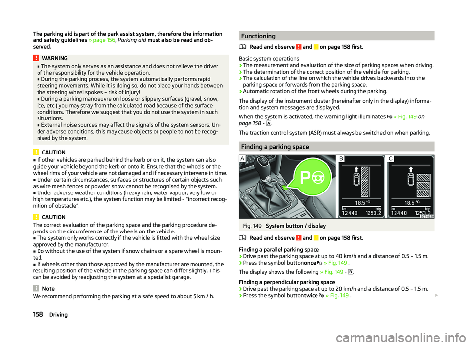
Fig. 149
System button / display
Read and observe
and on page 158 first.
Finding a parallel parking space
›
Drive past the parking space at up to 40 km/h and a distance of 0.5 – 1.5 m.
›
Press the symbol button once
» Fig. 149 .
The display shows the following » Fig. 149 -
.
Finding a perpendicular parking space
›
Drive past the parking space at up to 20 km/h and a distance of 0.5 – 1.5 m.
›
Press the symbol button twice
» Fig. 149 .
158Driving
Page 240 of 252
BootAutomatic retraction (Superb Combi)101
Extending variable loading floor105
Folding hook99
Non-closable side pocket (Superb Combi)102
Removable Light (Superb Combi)103
Roll up boot cover (Superb Combi)101
Side compartment with battery102
Boot cover (Superb Combi)101
Boot lid57
automatic locking58
Warning light36
(Superb Combi)58
Brake booster144
Brake fluid192
Checking193
Information messages35
specification193
Brake linings warning light
41
Brakes Brake assist systems
154
Brake booster144
Brake fluid193
Handbrake144
Information messages35
Running in149
Warning light35
Braking Information on braking
143
Break recommendation See Fatigue detection
165
Button in the driver's door Electrical power windows
61
C
Car care
173
Jack180
Car computer See multifunction display
44
Car park ticket holder89
Carrier Roof rack
108
Cavity protection180
CD changer136
Central locking50
Central locking button55
Changing brake fluid
193
bulbs223
Wheels205
Changing a wheel Follow-up work
206
Preliminary work206
Remove and attaching a wheel206
Changing brake fluid
193
Charging a vehicle battery196
Check Fit ball head properly
168
Checking Battery electrolyte level
195
Brake fluid193
Coolant192
Engine oil190
Oil level190
Windscreen washer fluid188
Checks Statutory checks
173
Children and safety22
Child safety Side airbag
24
Child safety lock55
Child seat Classification
25
ISOFIX25
on the front passenger seat23
TOP TETHER27
Use of child seats25
Use of ISOFIX child seats26
Chrome parts refer to Taking care of your vehicle178
Cigarette lighter91
Cleaning Alcantara
182
Covers of electrically heated seats182
Fabrics182
Headlight lenses179
Natural leather181
Plastic parts178
Synthetic leather182
Wheels180
Cleaning the vehicle Towing device
180
Cleaning vehicle176
Climatronic115
Air recirculation117
automatic mode116
Control elements115
Controlling blower118
Cooling system116
Defrosting windscreen118
Setting the temperature116
Clothes hook94
Cockpit 12-Volt power outlet
92
Ashtray91
Cigarette lighter91
General view29
Lighting73
Practical features88
Storage compartments88
Comfort control window
63
COMING HOME72
Compartments88
Components of the puncture repair kits209
Computer See multifunction display
44
237Index
Page 247 of 252
Switch off ignitionRefer to KESSY141
Switch on ignition Refer to KESSY
141
Synchronous adjustment of the rear-view mir- ror
80
Synthetic leather182
T
Tailgate TwinDoor
58
Taking care of the vehicle Natural leather
181
Seat belts183
Taking care of your vehicle Automatic car wash system
177
Cavity protection180
Chrome parts178
Cleaning the wheels180
Decorative films179
Door lock cylinders179
Headlight lenses179
High-pressure cleaner177
Plastic parts178
Polishing the paintwork178
Rubber seals178
Taking care of the interior181
Taking care of your vehicle exterior177
Washing by hand176
Wash system177
Wax treatment178
Taking care of your vehicles Fabric covers
182
Technical data228
Telephone124, 126
Temporary spare wheel200
Tilting roof see Electric sliding/tilting roof
64
Tiptronic146
Tools205
TOP TETHER27
Towing213
Towing a trailer171
Towing device Description
167
Operation and maintenance180
Towing eye Front
214
Rear214
Towing protection56
Traction Control System (ASR)155
Trailer170
13-pin socket170
connection and disconnection170
Loading171
Safety eye170
Towing a trailer171
Trailer operation166
Trailer stabilisation172
Transport Luggage compartment
97
Roof rack108
Transporting children safely22
Triangle204
TSA172
Turn signal69
Turn signal system Warning light
41
Twindoor see boot lid
57
Two-way radio systems121
Tyre Explanation of the labelling
201
see wheels201
Tyre inflation pressure Warning light
40
Tyre load bearing capacity Refer to Wheels
201
Tyre pressure monitoring165
Save tyre pressure values166
Tyre repair Preparations
210
Pressure test211
Sealing and inflating the tyre210
Tyres197
Inflation pressure198
Sizes198
Tyre wear indicator198
Tyre size201
see wheels201
U
Umbrella Tray
95
Underbody protection180
Unleaded petrol153
Unlock Vehicle key
51
Unlocking Individual settings
54
KESSY53
Remote control52
Unlocking and locking50
Using the information system42
Using the selector lever145
V
Variable loading floor
104
Dividing the luggage compartment104
Remove104
slides off on aluminium rails105
Vehicle battery Automatic load deactivation
197
Charging196
Checking the battery electrolyte level195
Cover195
Disconnecting and reconnecting196
244Index