tow SKODA SUPERB 2010 Owner´s Manual
[x] Cancel search | Manufacturer: SKODA, Model Year: 2010, Model line: SUPERB, Model: SKODA SUPERB 2010Pages: 252, PDF Size: 16.33 MB
Page 72 of 252
Daylight running lights (DAY LIGHT)Read and observe
on page 67 first.
The daytime running lights (hereafter only function) provide lighting for the
front of the vehicle.
The lights are switched on automatically if the following conditions are met.
The light switch is in the position
or
» Fig. 49 on page 68 .
The ignition is switched on.
The parking aid is activated.
Deactivating the function
›
Switch off the ignition.
›
Pull the turn signal- and main beam lever ( » Fig. 50 on page 69 ) towards
the steering wheel, push down and hold in this position.
›
Switch on the ignition.
›
Hold the lever in this position for at least 3 seconds after switching on the
ignition.
Activating the function
›
Switch off the ignition.
›
Pull the turning signal and main beam lever towards the steering wheel,
push it up and hold it in this position.
›
Switch on the ignition.
›
Hold the lever in this position for at least 3 seconds after switching on the
ignition.
On vehicles with MAXI DOT display, the function can be enabled or disabled in
the menu item Dayl. dri. light » page 47 .
WARNINGWhen the daytime running light is switched on, the parking lights (neither
at the front nor the rear) and the number plate lights are not lit. Therefore
always switch on the low beam when the visibility is poor.Turn signal and main beamFig. 50
Operating lever: Turn signal and
main beam operation
Read and observe on page 67 first.
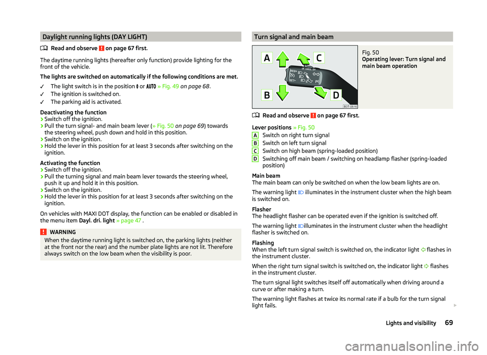
Lever positions » Fig. 50
Switch on right turn signal
Switch on left turn signal
Switch on high beam (spring-loaded position)
Switching off main beam / switching on headlamp flasher (spring-loaded
position)
Main beam
The main beam can only be switched on when the low beam lights are on.
The warning light illuminates in the instrument cluster when the high beam
is switched on.
Flasher
The headlight flasher can be operated even if the ignition is switched off.
The warning light illuminates in the instrument cluster when the headlight
flasher is switched on.
Flashing
When the left turn signal switch is switched on, the indicator light flashes in
the instrument cluster.
When the right turn signal switch is switched on, the indicator light flashes
in the instrument cluster.
The turn signal light switches itself off automatically when driving around a
curve or after making a turn.
The warning light flashes at twice its normal rate if a bulb for the turn signal
light fails.
ABCD69Lights and visibility
Page 73 of 252
“Convenience turn signal”
If you wish to flash three times only, briefly push the stalk to the upper or low-
er pressure point and release again.
The “Lane ch. flash” can be activated or deactivated via the MAXI DOT display
in the Lane ch. flash » page 47 menu item.WARNINGOnly turn on the main beam or the headlight flasher if other road users will
not be dazzled.
Automatic driving lamp control
Fig. 51
Light switch: AUTO position
Read and observe on page 67 first.
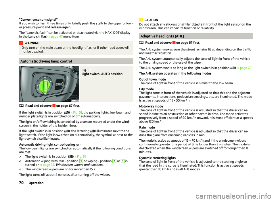
If the light switch is in position
» Fig. 51 , the parking lights, low beam and
number plate lights are switched on or off automatically.
The light on/off switching is controlled by a sensor mounted under the wind- screen in the holder of the inside mirror.
If the light switch is in position
, the lettering
illuminates next to the
light switch. If the light is switched on automatically, the symbol
next to the
light switch also illuminates.
Automatic driving-light control during rain
The low beam lights are switched on automatically if the following conditions
are met.
The light switch is in position
» Fig. 51 .
Automatic wiping with rain - position
1
or wiping - position
2
or
3
is
turned on » page 78, Windscreen wipers and washers .
The windscreen wipers are on for more than 15 s.
The light turns off about 4 minutes after turning off the wipers.
CAUTIONDo not attach any stickers or similar objects in front of the light sensor on the
windscreen. This can impair its function or reliability.
Adaptive headlights (AHL)
Read and observe
on page 67 first.
The AHL system makes sure the street remains lit up depending on the traffic
and weather situation.
The AHL system automatically adjusts the cone of light in front of the vehicle
to the driving speed or the use of the wiper.
The AHL system works as long as the light switch is in position .
» page 70
The AHL system operates in the following modes.
Out of town mode
The cone of light in front of the vehicle is similar to the low beam.
City mode
The light cone in front of the vehicle is adjusted so that this and the adjacent
pavements, intersections, pedestrian crossings, etc. are illuminated. The mode
is active at speeds of 15 - 50 km / h.
Motorway mode
The cone of light in front of the vehicle is adjusted so that the driver can re-
spond in time to an obstruction or other hazard in time. The mode activates
progressively from a speed of 90 km / h onward. It is most efficient at a speeds
above 120 km / h.
Rain mode
The cone of light in front of the vehicle is adjusted so that the driver can re-
duce the glare from oncoming vehicles in rain.
The mode is active at speeds of 15 – 70 km/h and if the windscreen wipers
continuously operate for a period of time longer than 2 minutes. The mode is
deactivated when the windscreen wipers are switched off for longer than 8
minutes.
Dynamic cornering lights
The cone of light in front of the vehicle is adjusted to the steering angle so
that the road in the curve is illuminated. This function is active at speeds
greater than 10 km.h and in all AHL modes.
70Operation
Page 75 of 252
Only the rear fog light on the trailer illuminates if the vehicle has a factory fit-
ted towing device or a towing device from ŠKODA original accessories and it is
driven with a trailer.
COMING HOME / LEAVING HOME
Read and observe
on page 67 first.
COMING HOME (hereinafter referred to only as function) switches the light au-
tomatically for a short time after leaving the vehicle.
LEAVING HOME (hereinafter referred to only as function) switches the light au-
tomatically for a short time when approaching the vehicle.
The lights are switched on automatically if the following conditions are met. The light switch is in position
» Fig. 51 on page 70 .
The visibility in the vehicle environment is reduced.
The ignition is switched off.
The parking aid is activated.
The function is switched on (the driver's door is opened / the car is un-
locked with the remote control).
The function switches on the following light, depending on the equipment
fitted.
› Parking lights
› Low beam
› Entry lighting in the exterior mirrors
› Licence plate light
Poorer visibility is evaluated by sensor mounted in the holder of the interior
mirror.
COMING HOME
The light turns on automatically when you open the driver's door on (within 60
seconds of turning off the ignition).
The light turns off 10 seconds after closing all the doors and the boot lid or af-
ter the pre-set time has expired.
If a door or the boot lid remains open, the light goes out after 60 seconds.
LEAVING HOME
The light turns on automatically after the vehicle is unlocked with the remote
control.
The light turns off after 10 seconds or after a pre-set time or after the vehicle
is locked.
Activate/deactivate the function
The functions and settings of the illumination time can be activated/deactiva-
ted via the MAXI DOT display in the menu items Coming Home or Leaving
Home » page 47 .
CAUTION
■
Do not attach any stickers or similar objects in front of the light sensor on
the windscreen. This can impair its function or reliability.■
If this function is activated constantly, the battery will be heavily discharged
particularly in short-haul travel.
Hazard warning light system
Fig. 53
Button for hazard warning light
system
Read and observe on page 67 first.
Switching on/off
›
Press the
» Fig. 53 button.
All the turn signal lights on the vehicle flash at the same time when the hazard
warning light system is switched on. The warning light for the turn signals and
the warning light in the button also flash at the same time. The hazard warn-
ing light system can also be operated if the ignition is switched off.
The hazard warning light system will switch on automatically if one of the air-
bags is deployed.
If the turn signal light is switched on when the hazard warning light and the
ignition are both switched on, then only the turn signal light on the corre-
sponding vehicle side will flash.
72Operation
Page 79 of 252
Sun visorsFig. 59
Sun visor: fold down / pivot to door
Fig. 60
Sun visor: Auxiliary panel fold down / makeup mirror
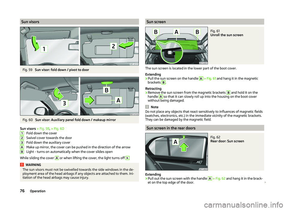
Sun visors » Fig. 59 , » Fig. 60
Fold down the cover
Swivel cover towards the door
Fold down the auxiliary cover
Make up mirror, the cover can be pushed in the direction of the arrow
Light - turns on automatically when the cover slides open
While sliding the cover
A
or when lifting the cover, the light turns off
B.WARNINGThe sun visors must not be swivelled towards the side windows in the de-
ployment area of the head airbags if any objects are attached to them. Ini-
tiation of the head airbags may cause injury.123ABSun screenFig. 61
Unroll the sun screen
The sun screen is located in the lower part of the boot cover.
Extending
›
Pull the sun screen on the handle
A
» Fig. 61 and hang it in the magnetic
brackets
B
.
Retracting
›
Remove the sun screen from the magnetic brackets
B
and hold it on the
handle
A
so that it can slowly roll up into the housing on the boot cover
without being damaged.
Note
Do not place any objects that react sensitively to influences of magnetic fields
(watches, electronics, etc.) in the immediate vicinity of the magnetic brackets.
They can be damaged by the magnetic field.
Sun screen in the rear doors
Fig. 62
Rear door: Sun screen
Extending
›
Pull out the sun screen with the handle
A
» Fig. 62 and hang it in the brack-
et on the top edge of the door.
76Operation
Page 95 of 252
WARNINGNever place flammable objects in the ashtray – risk of fire!
Note
The ashtrays are fitted with an interior light which illuminates when the park-
ing light is on.
12 Volt power outlet
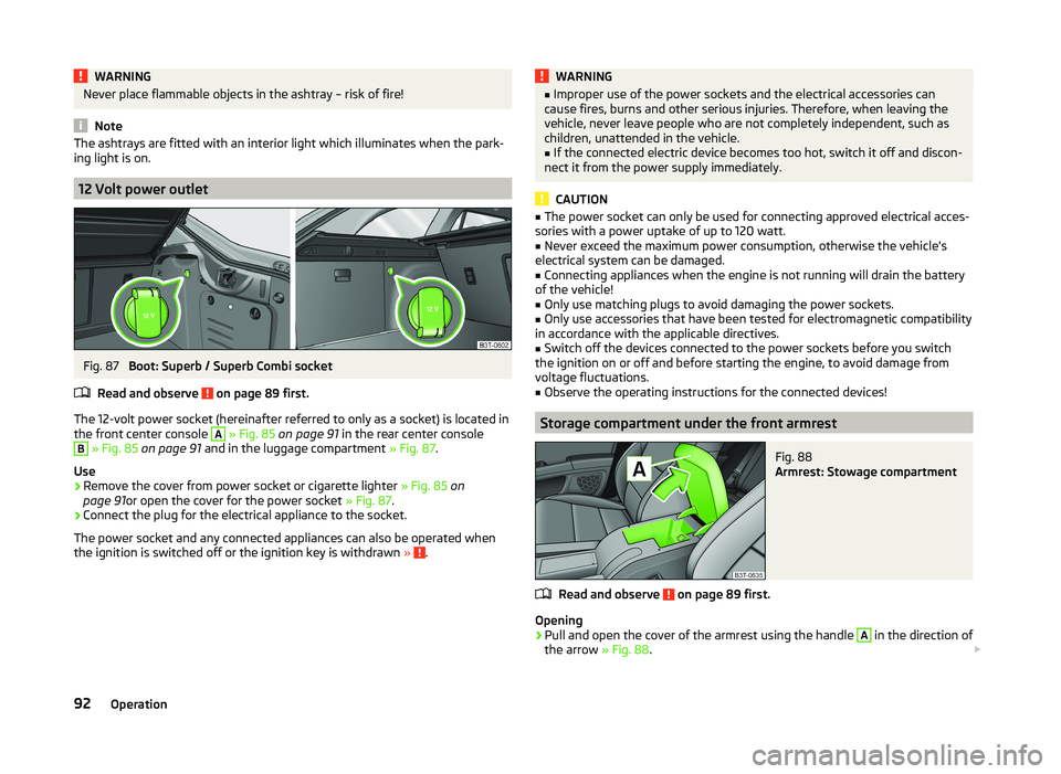
Fig. 87
Boot: Superb / Superb Combi socket
Read and observe
on page 89 first.
The 12-volt power socket (hereinafter referred to only as a socket) is located in the front center console
A
» Fig. 85 on page 91 in the rear center console
B
» Fig. 85 on page 91 and in the luggage compartment » Fig. 87.
Use
›
Remove the cover from power socket or cigarette lighter » Fig. 85 on
page 91 or open the cover for the power socket » Fig. 87.
›
Connect the plug for the electrical appliance to the socket.
The power socket and any connected appliances can also be operated when
the ignition is switched off or the ignition key is withdrawn »
.
WARNING■
Improper use of the power sockets and the electrical accessories can
cause fires, burns and other serious injuries. Therefore, when leaving the
vehicle, never leave people who are not completely independent, such as
children, unattended in the vehicle.■
If the connected electric device becomes too hot, switch it off and discon-
nect it from the power supply immediately.
CAUTION
■ The power socket can only be used for connecting approved electrical acces-
sories with a power uptake of up to 120 watt.■
Never exceed the maximum power consumption, otherwise the vehicle's
electrical system can be damaged.
■
Connecting appliances when the engine is not running will drain the battery
of the vehicle!
■
Only use matching plugs to avoid damaging the power sockets.
■
Only use accessories that have been tested for electromagnetic compatibility
in accordance with the applicable directives.
■
Switch off the devices connected to the power sockets before you switch
the ignition on or off and before starting the engine, to avoid damage from
voltage fluctuations.
■
Observe the operating instructions for the connected devices!
Storage compartment under the front armrest
Fig. 88
Armrest: Stowage compartment
Read and observe on page 89 first.
Opening
›
Pull and open the cover of the armrest using the handle
A
in the direction of
the arrow » Fig. 88.
92Operation
Page 97 of 252
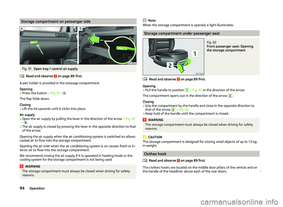
Storage compartment on passenger sideFig. 91
Open tray / control air supply
Read and observe
on page 89 first.
A pen holder is provided in the stowage compartment.
Opening
›
Press the button » Fig. 91 -
.
The flap folds down.
Closing
›
Lift the lid upwards until it clicks into place.
Air supply
›
Open the air supply by pulling the lever in the direction of the arrow » Fig. 91
- .
›
The air supply is closed by pressing the lever in the opposite direction to that
of the arrow.
Opening the air supply when the air conditioning system is switched on allows cooled air to flow into the storage compartment.
Opening the air inlet when the air conditioning system is on causes fresh or in-
terior air to flow into the storage compartment.
We recommend closing the air supply if it is operated in heating mode or the
cooling system for the storage compartment is not being used.
WARNINGThe storage compartment must always be closed when driving for safety
reasons.NoteWhen the storage compartment is opened, a light illuminates.
Storage compartment under passenger seat
Fig. 92
Front passenger seat: Opening
the storage compartment
Read and observe on page 89 first.
Opening
›
Pull the handle to position
1
» Fig. 92 in the direction of the arrow.
The compartment opens out in the direction of the arrow
2
.
Closing
›
Grip the compartment by the handle and close in the opposite direction to
that of the arrow
2
» Fig. 92 .
›
Keep hold of the handle until the compartment is closed.
WARNINGThe storage compartment must always be closed when driving for safety
reasons.
CAUTION
The storage compartment is designed for storing small objects of up to 1.5 kg.
in weight.
Clothes hook
Read and observe
on page 89 first.
The clothes hooks are located on the middle door pillars of the vehicle and onthe handle of the headliner above each of the rear doors.
94Operation
Page 98 of 252
WARNING■Only hang light items of clothing on the hooks. Never leave any heavy or
sharp-edged objects in the pockets of the items of clothing.■
Do not use clothes hangers for hanging up items of clothing; this may re-
duce the effectiveness of the head airbags.
■
Ensure that any clothes hanging from the hooks do not impair your vision
to the rear.
CAUTION
The maximum permissible load of the hooks is 2 kg.
Storage pockets on the front seats
Fig. 93
Map pockets
Read and observe on page 89 first.
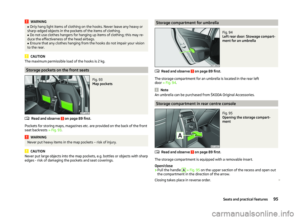
Pockets for storing maps, magazines etc. are provided on the back of the front
seat backrests » Fig. 93.
WARNINGNever put heavy items in the map pockets – risk of injury.
CAUTION
Never put large objects into the map pockets, e.g. bottles or objects with sharp
edges - risk of damaging the pockets and seat coverings.Storage compartment for umbrellaFig. 94
Left rear door: Stowage compart-
ment for an umbrella
Read and observe on page 89 first.
The storage compartment for an umbrella is located in the rear left
door » Fig. 94 .
Note
An umbrella can be purchased from ŠKODA Original Accessories.
Storage compartment in rear centre console
Fig. 95
Opening the storage compart-
ment
Read and observe on page 89 first.
The storage compartment is equipped with a removable insert.
Open/close
›
Pull the handle
A
» Fig. 95 on the upper section of the recess and open out
the compartment in the direction of the arrow.
Closing takes place in reverse order.
95Seats and practical features
Page 100 of 252
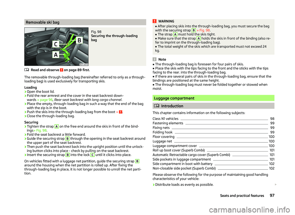
Removable ski bagFig. 98
Securing the through-loading
bag
Read and observe on page 89 first.
The removable through-loading bag (hereinafter referred to only as a through- loading bag) is used exclusively for transporting skis.
Loading
›
Open the boot lid.
›
Fold the rear armrest and the cover in the seat backrest down-
wards » page 96 , Rear seat backrest with long cargo channel .
›
Place the empty, through-loading bag in such a way that the end of the bag
with the zip is in the boot.
›
Push the skis into the through-loading bag from the boot » .
›
Close the through-loading bag.
Securing
›
Tighten the strap
A
on the free end around the skis in front of the bind-
ings » Fig. 98 .
›
Fold the seat backrest a little forward.
›
Guide the securing strap
B
through the opening in the seat backrest around
the upper part of the seat backrest.
›
Then push the seat backrest back into the upright position until the unlock-
ing button clicks into place - check by pulling on the seat backrest.
›
Insert the securing strap
B
into the lock
C
until it clicks into place.
On vehicles fitted with a luggage net partition, guide the securing strap
B
around the housing when the net partition is rolled up. After fixing the
through-loading bag in place, it is not longer possible to unroll the net parti-
tion.
WARNING■ After placing skis into the through-loading bag, you must secure the bag
with the securing strap B » Fig. 98 .■
The strap
A
must hold the skis tight.
■
Make sure that the strap
A
holds the skis in front of the binding (also re-
fer to imprint on the through-loading bag).
■
The total weight of the skis which are transported must not exceed 24
kg.
Note
■ The through-loading bag is foreseen for four pairs of skis.■Place the skis with the tips facing to the front and the sticks with the tips
facing to the rear. into the through-loading bag.■
If there are several pairs of skis in the through-loading bag, ensure that the
bindings are positioned at the same height.
■
The through-loading bag must never be folded together or stowed when
moist.
Luggage compartment
Introduction
This chapter contains information on the following subjects:
Class N1 vehicles
98
Fastening elements
99
Fixing nets
99
Folding hook
99
Floor covering
100
Luggage net
100
Luggage compartment cover
100
Roll up boot cover (Superb Combi)
101
Automatic Retractable cargo cover (Superb Combi)
101
Side pockets in luggage compartment
101
Side compartment in boot with battery
102
Non-closable side pocket (Superb Combi)
102
Please observe the following for the purpose of maintaining good handling
characteristics of your vehicle:
›
Distribute loads as evenly as possible.
97Seats and practical features
Page 101 of 252
›Place heavy objects as far forward as possible.›Attach the items of luggage to the lashing eyes or using the
nets » page 99 .
In the event of an accident, even small and light objects gain so much kinetic
energy that they can cause severe injuries.
The magnitude of the kinetic energy is dependent on the speed at which the
vehicle is travelling and the weight of the object.
Example: In the event of a frontal collision at a speed of 50 km/h, an object
weighing 4.5 kg produces energy corresponding to 20 times its own weight.
This means that it results in a weight of approx. 90 kg “ ”.
Luggage compartment light
The light switches on/off when the luggage compartment lid is opened or
closed.
If the boot lid is open and the ignition switched off, the light will extinguish
automatically after around 10 minutes.
Boot light for Superb Combi vehicles » page 103.WARNING■
Always store transported objects in the boot and attach them to the lash-
ing eyes.■
Loose objects can be thrown forward during a sudden manoeuvre or in
case of an accident and can injure the occupants or other road users.
■
Loose objects could hit a deployed airbag and injure occupants – there is
a risk of death.
■
Please note that transporting heavy objects alters the handling proper-
ties of the vehicle due to the displacement of the centre of gravity – risk of
accident! The speed and style of driving must be adjusted accordingly.
■
If the items of luggage or objects are attached to the lashing eyes with
unsuitable or damaged lashing straps, injuries can occur in the event of
braking manoeuvres or accidents. To prevent items of luggage from moving
around, always use suitable lashing straps that are firmly attached to the
lashing eyes.
■
The transported items must be stowed in such a way that no objects are
able to slip forward on sudden driving or braking manoeuvres – risk of in-
jury!
WARNING (Continued)■ When transporting objects in the luggage compartment that has been en-
larged by folding the rear seats forward, ensure the safety of the passen-
gers transported on the other rear seats » page 11.■
If the rear seat next to the folded forward seat is occupied, ensure maxi-
mum safety, e.g. by placing the goods to be transported in such a way that
the seat is prevented from folding back in case of a rear collision.
■
Do not drive with the luggage compartment lid open or unlatched, other-
wise exhaust gases may get into the interior of the vehicle – risk of poison-
ing!
■
Do not exceed the permissible axle loads and permissible gross weight of
the vehicle – risk of accident!
■
Do not transport people in the boot!
CAUTION
■ It is important to ensure that the heating elements of the rear window heat-
er, the threads of the integrated antenna in the rear window as well as the
threads of the integrated antenna (Superb Combi) in the rear side windows,
are not damaged by abrasive items.■
Tyre pressure must be adjusted to the load » page 198.
Class N1 vehicles
Read and observe
and on page 98 first.
On class N1 vehicles, which are not fitted with a protective grille, a lashing set
which complies with the standard EN 12195 (1 - 4) must be used for fastening
the load.
The proper functioning of the electrical system is essential for the safe opera-
tion of the vehicle. It is important to ensure that it is not damaged during mod-
ifications or when loading or unloading the luggage compartment.
98Operation
Page 103 of 252
Floor coveringFig. 102
Fixing the floor covering: Superb / Superb Combi
Read and observe
and on page 98 first.
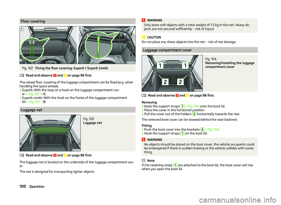
The raised floor covering of the luggage compartment can be fixed (e.g. when
handling the spare wheel):
› Superb: With the loop on a hook on the luggage compartment cov-
er » Fig. 102 –
.
› Superb combi: With the hook on the frame of the luggage compartment
lid » Fig. 102 -
.
Luggage net
Fig. 103
Luggage net
Read and observe and on page 98 first.
The luggage net is located on the underside of the luggage compartment cov-
er.
The net is designed for transporting lighter objects.
WARNINGOnly store soft objects with a total weight of 1.5 kg in the net. Heavy ob-
jects are not secured sufficiently – risk of injury!
CAUTION
Do not place any sharp objects into the net – risk of net damage.
Luggage compartment cover
Fig. 104
Removing/installing the luggage
compartment cover
Read and observe and on page 98 first.
Removing
›
Hook the support straps
1
» Fig. 104 onto the boot lid.
›
Place the cover in the horizontal position.
›
Pull the cover out of the holders
2
horizontally towards the rear.
The removed boot cover can be stowed behind the seat backrest.
Fitting
›
Push the boot cover into the brackets
2
» Fig. 104 .
›
Hook the support straps
1
on the boot lid.
WARNINGNo objects should be placed on the boot cover, the vehicle occupants could
be endangered if there is sudden braking or the vehicle collides with some-
thing.
Note
If the retaining strips 1 are attached to the boot lid, the boot cover will rise
when you open the boot lid.100Operation