engine SKODA SUPERB 2010 Owner´s Manual
[x] Cancel search | Manufacturer: SKODA, Model Year: 2010, Model line: SUPERB, Model: SKODA SUPERB 2010Pages: 252, PDF Size: 16.33 MB
Page 158 of 252
Antilock brake system (ABS)Read and observe
and on page 154 first.
ABS prevents the wheels locking when braking. Thereby, it helps the driver to
maintain control of the vehicle.
The intervention of the ABS is noticeable from the pulsating movements of
the brake pedal which is accompanied by noises.
When the ABS system is active, do not brake periodically or reduce the pres-
sure on the brake pedal.
Traction Control System (ASR)
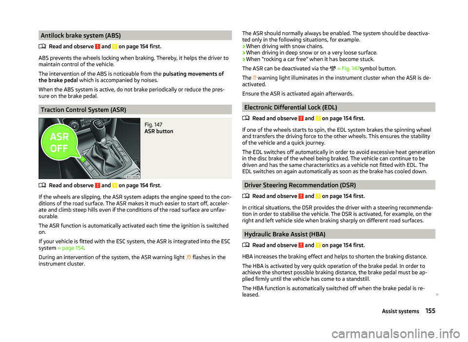
Fig. 147
ASR button
Read and observe and on page 154 first.
If the wheels are slipping, the ASR system adapts the engine speed to the con- ditions of the road surface. The ASR makes it much easier to start off, acceler-
ate and climb steep hills even if the conditions of the road surface are unfav-
ourable.
The ASR function is automatically activated each time the ignition is switched
on.
If your vehicle is fitted with the ESC system, the ASR is integrated into the ESC
system » page 154 .
During an intervention of the system, the ASR warning light flashes in the
instrument cluster.
The ASR should normally always be enabled. The system should be deactiva-
ted only in the following situations, for example.
› When driving with snow chains.
› When driving in deep snow or on a very loose surface.
› When “rocking a car free” when it has become stuck.
The ASR can be deactivated via the
» Fig. 147 symbol button.
The
warning light illuminates in the instrument cluster when the ASR is de-
activated.
Ensure the ASR is activated again afterwards.
Electronic Differential Lock (EDL)
Read and observe
and on page 154 first.
If one of the wheels starts to spin, the EDL system brakes the spinning wheel
and transfers the driving force to the other wheels. This ensures the stability
of the vehicle and a quick journey.
The EDL switches off automatically in order to avoid excessive heat generation
in the disc brake of the wheel being braked. The vehicle can continue to be
driven and has the same characteristics as a vehicle not fitted with EDL. The
EDL switches on again automatically as soon as the brake has cooled down.
Driver Steering Recommendation (DSR)
Read and observe
and on page 154 first.
In critical situations, the DSR provides the driver with a steering recommenda-tion in order to stabilise the vehicle. The DSR is activated, for example, on the
right and left vehicle side when braking sharply on different road surfaces.
Hydraulic Brake Assist (HBA)
Read and observe
and on page 154 first.
HBA increases the braking effect and helps to shorten the braking distance.The HBA is activated by very quick operation of the brake pedal. In order to
achieve the shortest possible braking distance, the brake pedal must be ap-
plied firmly until the vehicle has come to a standstill.
The HBA function is automatically switched off when the brake pedal is re-
leased.
155Assist systems
Page 164 of 252
The system cannot be activated because a fault exists on the vehicle. Seek
help from a specialist garage.
Park Assist stopped. System not available right now.
The parking procedure was ended because a fault exists on the vehicle. Seek
help from a specialist garage.
Park Assist faulty. Workshop!
The parking procedure is not possible because a fault exists in the system.
Seek help from a specialist garage.
ASR intervention. Take over steering!
The parking procedure is terminated by an ASR intervention. PARK ASSIST Turn on turn signal and select reverse gear
The prerequisites for manoeuvring out of a parking space using the system
have been met. Switch on the turn signals and shift into reverse.
Automatic space departure not possible. Space too small.
The manoeuvring procedure using the system is not possible. The parking gap
is too small.
Park Assist: Brake interv. Speed too high.
The speed was too high during the parking and was automatically reduced.
Cruise Control System
Introduction
This chapter contains information on the following subjects:
Activating/deactivating
161
Storing and maintaining speed
162
Changing the stored speed
162
Switching off temporarily
162
The Cruise Control System (CCS) maintains a set speed, more than 25 km/h,
without you having to actuate the accelerator pedal.
This is only possible within the range which is permitted by the power output and braking power of the engine.
The warning light in the instrument cluster illuminates when the cruise con-
trol system is switched on.
WARNING■ For safety reasons, the cruise control system must not be used in dense
traffic or on unfavourable road surfaces (such as icy roads, slippery roads,
loose gravel) – there is a risk of an accident.■
The saved speed may only be resumed if it is not too high for the current
traffic conditions.
■
Always deactivate the cruise control system after use to prevent the sys-
tem being switched on unintentionally.
CAUTION
■ The cruise control system is not able to maintain a constant speed when
driving in areas with steeper gradients. The weight of the vehicle increases the
speed at which it travels. In such cases, select a lower gear or slow the vehicle
using the footbrake.■
The cruise control system cannot be activated when first gear or reverse
gear is selected (vehicles with manual transmission).
■
The cruise control system cannot be activated when the selector lever is in
positions P, N or R (vehicles with automatic transmission).
■
The Cruise Control System may automatically switch off when some brake
assist systems (e.g. ESC) intervene, when the speed exceeds maximum permis-
sible engine speed, or a similar event takes place.
Activating/deactivating
Fig. 151
Operating lever: Cruise control
system controls
Read and observe and on page 161 first.
Activating
›
Move switch
A
» Fig. 151 into the ON position.
Deactivating
›
Move switch
A
» Fig. 151 into the OFF position.
161Assist systems
Page 165 of 252
Storing and maintaining speedRead and observe
and on page 161 first.
›
Activate the cruise control system » page 161.
›
Drive at the desired speed.
›
Push the rocker button
B
into the SET/- » Fig. 151 on page 161 position.
After you have released the rocker button
B
from the SET/- position, the
speed you have just stored is kept constant without having to depress the ac-
celerator.
Changing the stored speed
Read and observe
and on page 161 first.
Increasing the speed with the rocker button
B›
Push the rocker button
B
into the RES/+ » Fig. 151 on page 161 position.
If the rocker button is held in the RES/+ position, the speed will increase con-
tinuously. Release the rocker button once the desired speed is reached. The
set speed is then stored in the memory.
Decreasing the speed using the rocker button
B
The stored speed can be reduced by pushing the rocker switch
B
into the
SET/- » Fig. 151 on page 161 position.
If the rocker button is pressed and held in the SET/- position, the speed will
decrease continuously. Release the rocker button once the desired speed is
reached. The set speed is then stored in the memory.
If the rocker button is released at a speed of less than approx. 25 km/h, the
speed is not stored and the memory is erased. Once the speed of the vehicle
has increased to more than approx. 25 km/h, the speed must then be stored
again by pushing the rocker button
B
into the SET/- position.
Increasing the speed with the accelerator
›
Depress the accelerator pedal.
Releasing the accelerator pedal will cause the speed to drop again to the set
speed.
Decreasing the speed with the brake pedal
The speed can also be reduced by depressing the brake pedal, which tempora-
rily deactivates the system » page 162.
Switching off temporarily
Read and observe
and on page 161 first.
The cruise control system can be temporarily deactivated by pushing the
switch
A
» Fig. 151 on page 161 into the spring-mounted CANCEL position or
by depressing the brake or clutch pedal.
The set speed remains stored in the memory.
Briefly push the rocker button
B
into the RES/+ position in order to resume
the stored speed after the clutch or brake pedal is released.
START STOP
Introduction
This chapter contains information on the following subjects:
Operating conditions for the system
163
Operation in vehicles with manual gearbox
163
Operation in vehicles with automatic gearbox
163
System related automatic start-up
164
Manually deactivating/activating the system
164
Information messages
164
The START STOP system (hereinafter referred to as the system) saves fuel and
reduces polluting emissions and CO 2 emissions by turning the engine off, e.g.
when stopping at traffic lights, and starting the engine again when moving off.
WARNING■ Never let the vehicle roll with the engine switched off.■The brake servo unit and power steering only operate if the engine is run-
ning.162Driving
Page 166 of 252
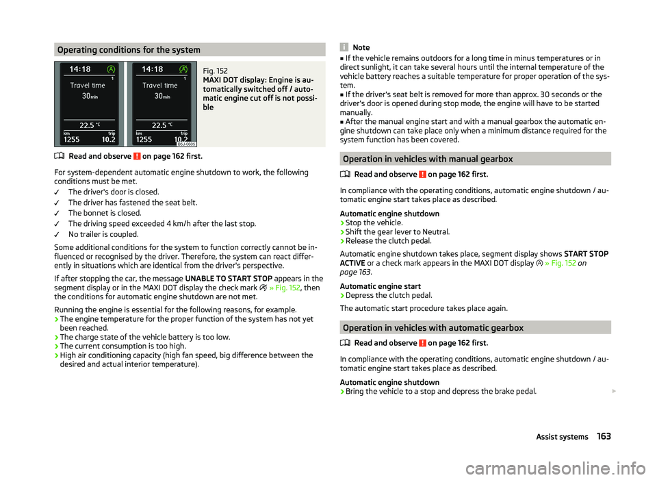
Operating conditions for the systemFig. 152
MAXI DOT display: Engine is au-
tomatically switched off / auto-
matic engine cut off is not possi-
ble
Read and observe on page 162 first.
For system-dependent automatic engine shutdown to work, the following
conditions must be met.
The driver's door is closed.
The driver has fastened the seat belt.
The bonnet is closed.
The driving speed exceeded 4 km/h after the last stop.
No trailer is coupled.
Some additional conditions for the system to function correctly cannot be in-
fluenced or recognised by the driver. Therefore, the system can react differ-
ently in situations which are identical from the driver's perspective.
If after stopping the car, the message UNABLE TO START STOP appears in the
segment display or in the MAXI DOT display the check mark
» Fig. 152 , then
the conditions for automatic engine shutdown are not met.
Running the engine is essential for the following reasons, for example.
› The engine temperature for the proper function of the system has not yet
been reached.
› The charge state of the vehicle battery is too low.
› The current consumption is too high.
› High air conditioning capacity (high fan speed, big difference between the
desired and actual interior temperature).
Note■ If the vehicle remains outdoors for a long time in minus temperatures or in
direct sunlight, it can take several hours until the internal temperature of the
vehicle battery reaches a suitable temperature for proper operation of the sys-
tem.■
If the driver's seat belt is removed for more than approx. 30 seconds or the
driver's door is opened during stop mode, the engine will have to be started
manually.
■
After the manual engine start and with a manual gearbox the automatic en-
gine shutdown can take place only when a minimum distance required for the
system function has been covered.
Operation in vehicles with manual gearbox
Read and observe
on page 162 first.
In compliance with the operating conditions, automatic engine shutdown / au-
tomatic engine start takes place as described.
Automatic engine shutdown
›
Stop the vehicle.
›
Shift the gear lever to Neutral.
›
Release the clutch pedal.
Automatic engine shutdown takes place, segment display shows START STOP
ACTIVE or a check mark appears in the MAXI DOT display
» Fig. 152 on
page 163 .
Automatic engine start
›
Depress the clutch pedal.
The automatic start procedure takes place again.
Operation in vehicles with automatic gearbox
Read and observe
on page 162 first.
In compliance with the operating conditions, automatic engine shutdown / au-
tomatic engine start takes place as described.
Automatic engine shutdown
›
Bring the vehicle to a stop and depress the brake pedal.
163Assist systems
Page 167 of 252
Automatic engine shutdown takes place, segment display shows START STOP
ACTIVE or a check mark appears in the MAXI DOT display » Fig. 152 on
page 163 .
Automatic engine start›
Release the brake pedal.
The automatic start procedure takes place again.
Further information on automatic transmission
The automatic engine shut down takes place when the selector lever is in po-
sitions P, D , S and N and in Tiptronic mode.
When the selector lever is in position P, the engine remains shut down even
after you release the brake pedal. The engine starts automatically by pressing
the gas pedal or by moving the selector lever into a different mode and releas-
ing the brake pedal.
If the engine is off due to the automatic and the selector lever is put to the R
position, then the automatic start-up of the engine.
If the gear selector is moved from position R to the position D, S or N, the vehi-
cle must reach a speed of more than 10 km / h before the automatic engine
shutdown starts.
There is no automatic engine shutdown when the system detects a vehicle
moving due to a large steering angle.
No automatic engine shutdown takes place when the vehicle is moving at low
speed (e.g. during a traffic jam or when turning) and remains stationary after
pressing the brake pedal lightly. Automatic engine shutdown takes place if you
press the brake pedal down with more force.
System related automatic start-up
Read and observe
on page 162 first.
When the engine is off, the system can automatically start the engine beforethe desired journey continues. Some possible reasons for this are:
› The vehicle has begun to roll, e.g. on a slope.
› The brake pedal has been actuated several times.
› The current consumption is too high.
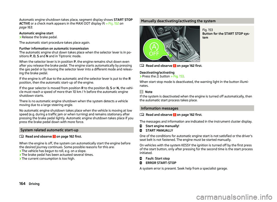
Manually deactivating/activating the systemFig. 153
Button for the START STOP sys-
tem
Read and observe on page 162 first.
Deactivating/activating
›
Press the button
» Fig. 153 .
When start stop mode is deactivated, the warning light in the button illumi-
nates.
Note
If the system is deactivated when the engine is turned off automatically, then
the automatic start process takes place.
Information messages
Read and observe
on page 162 first.
The messages and information are indicated in the instrument cluster display. Start engine manually!
START MANUALLY
One of the conditions for automatic engine start is not satisfied or the driver's
seat belt is not fastened. The engine must be started manually.
On vehicles with the system KESSY the ignition is turned off by the first press
of the start button, only after pressing for the second time is the start process
initiated.
Fault: Start stop
ERROR START-STOP
A system error is present. Seek help from a specialist garage.
164Driving
Page 174 of 252
Exterior mirrors
You have to have additional exterior mirrors fitted if you are not able to see
the traffic behind the trailer with the standard rear-view mirrors. National legal
requirements must be observed.
Headlights
The front of the vehicle can be lifted when a trailer is being towed and the
headlights can dazzle other road users.
Adjust the headlight setting on the headlight range control » page 68, Operat-
ing the lights and the instrument illumination .WARNING■
Incorrect or improperly connected electrical installation can cause acci-
dents and serious injury due to electric shock.■
Work on the electrical system must only be carried out by specialist ga-
rages.
■
Never directly connect the trailer's electrical system with the electrical
connections for the tail lights or other current sources.
■
After coupling the trailer and connecting up the power socket, check the
rear lights on the trailer to ensure they are working.
■
The handbrake on the towing vehicle must be applied when coupling and
uncoupling the trailer.
■
Never use the safety eyelet for towing!
CAUTION
Incorrect or improperly connected electrical installations may cause malfunc-
tion of the entire vehicle electronics.
Loading a trailer
The vehicle/trailer combination must be balanced, whereby the maximum per-
missible drawbar load must be utilised. If the drawbar load is too low, it jeop-
ardises the performance of the vehicle/trailer combination.
Distribution of the load
Distribute the load in the trailer in such a way that heavy items are located as
close to the axle as possible. Secure the items from slipping.
The distribution of the weight is very poor if your vehicle is unladen and the
trailer is laden. Maintain a particularly low speed if you cannot avoid driving
with this combination.
Tyre pressure
Correct the tyre inflation pressure on your vehicle for a “full load” » page 198.
Trailer load
The permissible trailer load must not be exceeded under any circumstan-
ces » page 228 , Technical data .
The details given in the vehicle's technical documentation always take prece- dence over the details in the Owner's Manual.
The trailer loads specified apply only to altitudes up to 1,000 metres above
mean sea level.
The engine output falls as altitude increases, as does the ability to climb.
Therefore, for every additional 1,000 m in height (or part), the maximum per-
missible towed weight must be reduced by 10 %.
The towed weight comprises the actual weights of the (loaded) towing vehicle
and the (loaded) trailer.
The trailer and drawbar load information on the type plate of the towing
equipment are merely test data for the towing equipment. The vehicle-specific
values are detailed in the vehicle documents.WARNING■ The maximum permissible axle and drawbar load and the permissible
weight of the trailer must not exceed - this could cause an accident!■
A sliding cargo can significantly adversely affect stability and driving safe-
ty - there is a risk of accident!
Towing a trailer
Driving speed
For safety reasons, do not drive faster than 80 km/h when towing a trailer.
Immediately reduce your speed as soon as even the slightest swaying of the
trailer is detected. Never attempt to stop the trailer from “swaying” by acceler-
ating.
Brakes
Apply the brakes in good time! If the trailer is fitted with a trailer brake, apply
the brakes gently at first and then brake firmly. This will avoid brake jolts re-
sulting from the trailer wheels locking.
On downhill sections shift down a gear in good time to also use the engine as
a brake.
171Hitch and trailer
Page 175 of 252
Engine overheating
The speed must be reduced immediately if the needle for the coolant tempera-
ture gauge moves into the right-hand area or the red area of the scale.
Stop and switch off the engine if the warning light
in the instrument cluster
illuminates.
The following guidelines must be observed » page 36,
Coolant .
The coolant temperature can be reduced by switching on the heating.WARNING■ Always drive particularly carefully with the trailer.■Adapt your speed to the conditions of the road surface and to the traffic
situation.
CAUTION
If you tow a trailer frequently, you should also have your vehicle inspected be-
tween service intervals.
Trailer stabilisation (TSA)
The trailer stabilisation is an extension of the stabilisation control that works
in conjunction with the counter-steering assistance to reduce the amount the
trailer "sways".
After turning on the ignition, the ESC warning light
in the instrument cluster
illuminates for about 2 seconds longer than the ABS warning light.
Function requirements for trailer stabilisation. The trailer was shipped from the factory or purchased from the ŠKODA
genuine accessories.
The ESC is active. (Warning lights
or
do not illuminate in the instru-
ment cluster).
The trailer is electrically connected to the towing vehicle by means of the
trailer socket.
The speed is higher than approx. 60 km/h.
The trailer has a rigid drawbar.
WARNING■ The increased safety offered by the trailer stabilisation must not tempt
you to take greater risks than otherwise.■
Avoid abrupt and sudden driving and braking manoeuvres - there is a risk
of accidents.
CAUTION
■ The trailer stabilisation need not be able to correctly detect all of driving sit-
uations.■
Light trailers that sway are not always detected and therefore stabilised ac-
cordingly by the trailer stabilisation.
■
Release the pressure on the accelerator pedal if the system is being regula-
ted.
Note
The trailer stabilisation works for both braked and unbraked trailers.
Anti-theft alarm system
When the vehicle is locked, the alarm is activated when the electrical connec-
tion to the trailer is interrupted.
Always switch off the anti-theft alarm system before a trailer is coupled or un-
coupled » page 55 .
Conditions for including a trailer in the anti-theft alarm system. The vehicle is factory fitted with an anti-theft alarm system and towing
equipment.
The trailer is electrically connected to the towing vehicle by means of the
trailer socket.
The electrical system of the vehicle and trailer is functional.
The vehicle is locked with the vehicle key and the anti-theft alarm system
is activated.
CAUTION
For technical reasons, trailers with rear LED lights cannot be connected to the
anti-theft alarm system.172Driving
Page 183 of 252
Cavity protectionRead and observe
and on page 177 first.
All the cavities of your vehicle which are at risk from corrosion are protectedfor life by a layer of protective wax applied in the factory.
This wax protection does not need to be inspected or re-applied.
If any small amount of wax flow out of the cavities at high temperatures, these
must be removed with a plastic scraper and the stains cleaned using a petrole-
um cleaner.
WARNINGSafety regulations should be observed when using petroleum cleaner to re-
move wax – risk of fire!
Jack
Read and observe
and on page 177 first.
The jack is maintenance-free.
If necessary, the moving parts of the jack should be lubricated with a suitable lubricant.
Wheels
Read and observe
and on page 177 first.
Wheel rims
Also thoroughly wash the wheel rims when washing the vehicle on a regular basis.
Regularly remove salt and brake abrasion, otherwise the rim material will be
corroded.
Damage to the paint layer on the wheel rims must be touched up immediately.
Light alloy wheels
After washing thoroughly and treat the wheel rims with a protective product
for light alloy wheels. Products which cause abrasion must not be used to
treat the wheel rims.
CAUTIONSevere layers of dirt on the wheels can also result in wheel imbalance. This
may show itself in the form of a wheel vibration which is transmitted to the
steering wheel which, in certain circumstances, can cause premature wear of
the steering. This means it is necessary to remove the dirt.
Towing device and mounting recess
Read and observe
and on page 177 first.
Close the mounting recess with the cap to prevent any ingress of dirt.
If dirt is present, clean the inner surfaces of the mounting recess and treat
with a suitable preservative.
Always check the ball head before hitching a trailer. Apply a suitable grease, if
necessary.
Fit the protective cap when stowing away the ball head to protect the luggage
compartment against dirt.
CAUTION
Apply grease to the inner part of the mounting recess. Make sure you do not
remove any grease.
Underbody protection
Read and observe
and on page 177 first.
The underside of your vehicle is protected for life against chemical and me-
chanical influences.
When driving, it cannot be guaranteed that no damage to the protective layer
will occur.
We recommend having the protective layer underneath the vehicle and the
chassis checked — preferably before the beginning of winter and at the end of
winter.
WARNINGNever use additional underbody protection or anti-corrosion agents for ex-
haust pipes, catalytic converters, diesel particle filters or heat shields.
When the engine reaches its operating temperature, these substances may ignite - risk of fire!180General Maintenance
Page 186 of 252
■Do not sit on wet seats - risk of seat deformation.■Always clean the seats “from seam to seam”.
Seat belts
Read and observe
and on page 181 first.
The belt webbing must always be kept clean.
Wash dirty seat belts with mild soapy water.
Remove coarse dirt with a soft brush.
Dirty belt webbing may impair the correct functioning of the inertia reel.
WARNING■ The seat belts must not be removed for cleaning.■Never clean the seat belts chemically as chemical cleaning products could
destroy the fabric.■
The seat belts must not be allowed to come into contact with corrosive
liquids (e.g. acids).
■
Check the condition of all the seat belts on a regular basis. If any damage
to the belt webbing, seat belt connections, inertia reel or lock is detected,
the seat belt must be replaced by a specialist garage.
■
The seat belts must be fully dried before being rolled up.
Inspecting and replenishing
Fuel
Introduction
This chapter contains information on the following subjects:
Refuelling
184
Unleaded petrol
184
Diesel fuel
185
The correct grades of fuel for your vehicle are stated on a sticker affixed to the
inside of the fuel filler flap » Fig. 162 on page 184 -
.
WARNINGThe national legal requirements must be observed if carrying a spare canis-
ter in the vehicle. We do not recommend carrying any fuel canisters in your
vehicle for safety reasons. in the event of an accident, these canisters can
become damaged and fuel may escape – risk of fire!
CAUTION
■ Never drive until the fuel tank is completely empty! The irregular supply of
fuel can cause misfiring, which can result in damage to parts of the engine and
the exhaust system.■
Immediately remove any fuel that has spilled onto the vehicle's paintwork –
risk of paint damage!
■
If the vehicle was not purchased in the country in which it was intended to
be operated, you should check whether the fuel specified by the manufacturer
is offered in the country where the vehicle will be operated. You should also
perhaps check whether the manufacturer has recommended a different fuel
for operation of the vehicle in the country concerned. If no prescribed fuel is
available, then you must check whether it is permitted by the manufacturer to
operate the vehicle with another fuel type.
183Inspecting and replenishing
Page 187 of 252
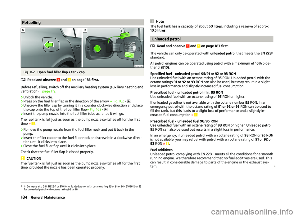
RefuellingFig. 162
Open fuel filler flap / tank cap
Read and observe
and on page 183 first.
Before refuelling, switch off the auxiliary heating system (auxiliary heating and
ventilation) » page 119.
›
Unlock the vehicle.
›
Press on the fuel filler flap in the direction of the arrow » Fig. 162 -
.
›
Unscrew the filler cap by turning it in a counter clockwise direction and place
the cap onto the top of the fuel filler flap » Fig. 162 -
.
›
Insert the pump nozzle into the fuel filler tube as far as it will go.
The fuel tank is full just as soon as the pump nozzle switches off for the first
time »
.
›
Remove the pump nozzle from the fuel filler neck and put it back in the
pump.
›
Insert the filler cap onto the fuel filler neck and screw it in a clockwise direc-
tion until it clicks into place.
›
Close the fuel filler flap until it clicks into place.
Check that the fuel filler flap is closed properly.
CAUTION
The fuel tank is full just as soon as the pump nozzle switches off for the first
time, provided the nozzle has been operated properly.NoteThe fuel tank has a capacity of about 60 litres, including a reserve of approx.
10.5 litres .
Unleaded petrol
Read and observe
and on page 183 first.
The vehicle can only be operated with unleaded petrol that meets the EN 2281)
standard.
All petrol engines can be operated using petrol with a maximum of 10% bioe-
thanol (E10).
Specified fuel - unleaded petrol 95/91 or 92 or 93 RON
Use unleaded fuel with an octane rating of 95 RON. Unleaded petrol with the
octane ratings 91 or 92 or 93 RON can also be used, but may result in a slight
loss in performance and slightly increased fuel consumption .
Prescribed fuel - unleaded petrol min. 95 RON
Use unleaded fuel with an octane rating of 95 RON or higher.
If unleaded gasoline is not available with the octane number 95 RON, in an
emergency petrol with the octane rating of 91 or 92 or 93 RON can be used to
fill the tank, but this leads to a slight loss of performance and a slightly in-
creased fuel consumption »
.
Prescribed fuel - unleaded fuel 98/95 RON
Use unleaded fuel with an octane rating of 98 RON or higher. Unleaded petrol
95 RON can also be used but results in a slight loss in performance.
In an emergency, if unleaded petrol with an octane rating of 98 RON or 95 RON
is not available, you may refuel with petrol with an octane rating of 91 or 92 or
93 RON »
.
Fuel additives
Unleaded petrol complying with EN 228 1 )
meets all the conditions for a smooth
running engine. We therefore recommend that no fuel additives are used. This
can result in considerable damage to parts of the engine or the exhaust sys-
tem.
1)
In Germany also DIN 51626-1 or E10 for unleaded petrol with octane rating 95 or 91 or DIN 51626-2 or E5
for unleaded petrol with octane rating 95 or 98.
184General Maintenance