Ac compressor SKODA SUPERB 2010 Owner´s Manual
[x] Cancel search | Manufacturer: SKODA, Model Year: 2010, Model line: SUPERB, Model: SKODA SUPERB 2010Pages: 252, PDF Size: 16.33 MB
Page 113 of 252

Air conditioning system
Heating, ventilation, cooling
Introduction
This chapter contains information on the following subjects:
Air outlets
110
Using the air conditioning system economically
111
Operational problems
112
The heating effect is dependent upon the coolant temperature, thus full heat
output only occurs when the engine has reached its operating temperature.
If the cooling system is switched on, the temperature and air humidity drops in
the vehicle. The cooling system prevents the windows from misting up during
winter months.
It is possible to briefly activate recirculated air mode to enhance the cooling
effect.
Please refer to the information regarding recirculated air mode for the air con-
ditioning system » page 114 or for Climatronic » page 117.
WARNING■
For your own safety and that of other road users, ensure that all the win-
dows are free of ice, snow and misting. Please familiarize yourself about
how to correctly operate the heating and ventilation systems, how to de-
mist and defrost the windows, as well as with the cooling mode.■
To reduce health risks (e.g. common colds), the following instructions for
the use of the cooling system are to be observed. ■The difference between the indoor temperature and the outdoor air
temperature should not be greater than about 5 ° C.
■ The cooling system is to be turned off about 10 minutes before the end
of the journey.
■ Once a year, a disinfection of the air conditioner or the Climatronic is to
be carried out by a specialist company.
CAUTION■ The air inlet in front of the windscreen must be free (e.g. of ice, snow or
leaves) to ensure that the heating and cooling system operates properly.■
After switching on the cooling Condensation from the evaporator of the air
conditioning may drip down and form a puddle below the vehicle. This is not a
leak.
Note
■ The exhaust air streams out through vents at the rear of the luggage com-
partment.■
We recommend that you do not smoke in the vehicle when the recirculating
air mode is operating since the smoke which is drawn at the evaporator from
the interior of the vehicle forms deposits in the evaporator of the air condition-
ing system. This produces a permanent odour when the air conditioning sys-
tem is operating which can only be eliminated through considerable effort and
expense (replacement of compressor).
Air outlets
Fig. 123
Air vents at the front
110Operation
Page 114 of 252
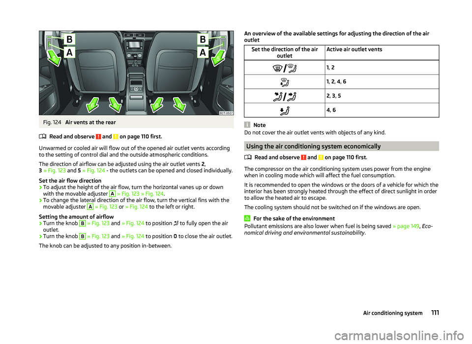
Fig. 124
Air vents at the rear
Read and observe
and on page 110 first.
Unwarmed or cooled air will flow out of the opened air outlet vents according to the setting of control dial and the outside atmospheric conditions.
The direction of airflow can be adjusted using the air outlet vents 2,
3 » Fig. 123 and 5 » Fig. 124 - the outlets can be opened and closed individually.
Set the air flow direction
›
To adjust the height of the air flow, turn the horizontal vanes up or down
with the movable adjuster
A
» Fig. 123 » Fig. 124 .
›
To change the lateral direction of the air flow, turn the vertical fins with the
movable adjuster
A
» Fig. 123 or » Fig. 124 to the left or right.
Setting the amount of airflow
›
Turn the knob
B
» Fig. 123 and » Fig. 124 to position
to fully open the air
outlet.
›
Turn the knob
B
» Fig. 123 and » Fig. 124 to position 0 to close the air outlet.
The knob can be adjusted to any position in-between.
An overview of the available settings for adjusting the direction of the air
outletSet the direction of the air outletActive air outlet vents1, 21, 2 , 4 , 6 2, 3 , 54 , 6
Note
Do not cover the air outlet vents with objects of any kind.
Using the air conditioning system economically
Read and observe
and on page 110 first.
The compressor on the air conditioning system uses power from the enginewhen in cooling mode which will affect the fuel consumption.
It is recommended to open the windows or the doors of a vehicle for which the
interior has been strongly heated through the effect of direct sunlight in order
to allow the heated air to escape.
The cooling system should not be switched on if the windows are open.
For the sake of the environment
Pollutant emissions are also lower when fuel is being saved » page 149, Eco-
nomical driving and environmental sustainability .111Air conditioning system
Page 212 of 252
Puncture set
Introduction
This chapter contains information on the following subjects:
Components of the puncture repair kits
209
Preparations for using the breakdown kit
210
Sealing and inflating the tyre
210
Notes for driving with tyre repaired
211
Use the breakdown kit to reliably repair tyre damage caused by foreign bodies
or a puncture with diameters up to approx. 4 mm.
A repair made using the breakdown kit is never intended to replace a perma-
nent repair on the tyre. Its purpose is to get you to the nearest specialist ga-
rage.
The wheel need not be removed during the repair.
Do not remove foreign bodies , e.g. screws or nails, from the tyre.
The breakdown kit must not be used under the following circumstances. › There is damage to the rim.
› The outside temperature is less than -20 °C.
› The tears or punctures are greater than 4 mm in size.
› There is damage to the tyre wall.
› Driving with very low tyre pressure or with a completely flat tyre.
› If the use-by-date (see inflation bottle) has passed.
WARNING■
If you are in flowing traffic, switch on the hazard warning light system
and set up the warning triangle at the prescribed distance! The national le-
gal requirements must be observed.■
Park the vehicle as far away as possible from the flow of traffic. Park on
as flat and firm a surface as possible.
WARNING■ A tyre filled with sealant has the same driving characteristics as a stand-
ard tyre.■
Do not drive faster than 80 km/h (50 mph).
■
Avoid accelerating at full throttle, sharp braking and fast cornering.
WARNING (Continued)■ The sealant is hazardous to heath. Remove immediately if it comes into
contact with the skin.■
Observe the manufacturer's usage instructions for the breakdown kit.
For the sake of the environment
Used sealant or sealant whose expiry date has passed must be disposed of in
accordance with environmental protection regulations.
Note
■ A new bottle of sealant can be purchased from ŠKODA Original Parts.■Immediately replace the tyre that was repaired using the breakdown kit, or
consult a specialist garage about repair options.■
The national legal requirements must be observed when repairing a tyre.
Components of the puncture repair kits
Fig. 183
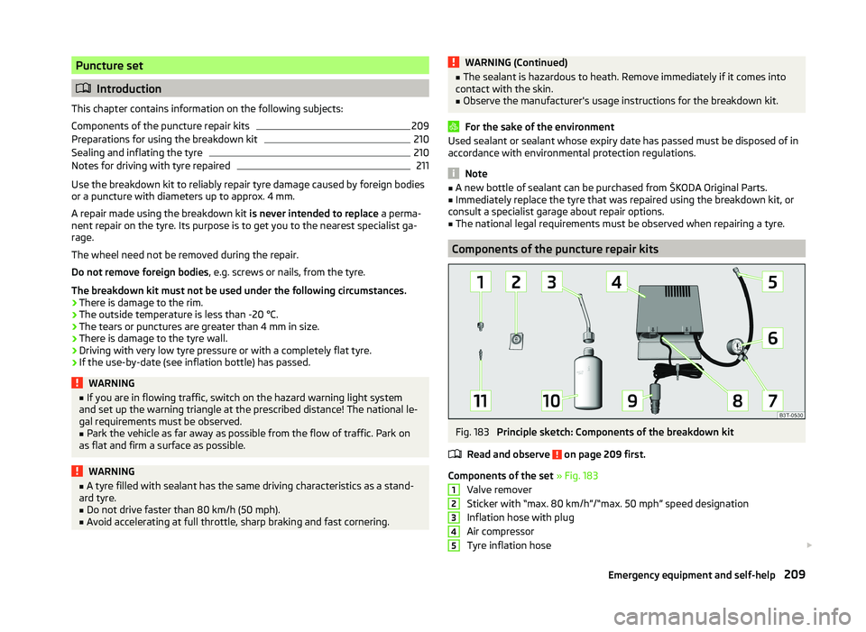
Principle sketch: Components of the breakdown kit
Read and observe
on page 209 first.
Components of the set » Fig. 183
Valve remover
Sticker with “max. 80 km/h”/“max. 50 mph” speed designation
Inflation hose with plug
Air compressor
Tyre inflation hose
12345209Emergency equipment and self-help
Page 213 of 252
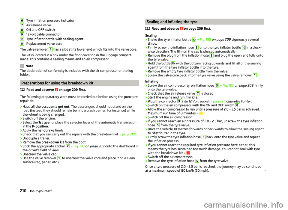
Tyre inflation pressure indicator
Air release valve
ON and OFF switch
12 volt cable connector
Tyre inflator bottle with sealing agent
Replacement valve core
The valve remover 1
has a slot at its lower end which fits into the valve core.
The kit is located in a box under the floor covering in the luggage compart-
ment. This contains a sealing means and an air compressor.
Note
The declaration of conformity is included with the air compressor or the log
folder.
Preparations for using the breakdown kit
Read and observe
on page 209 first.
The following preparatory work must be carried out before using the puncturerepair kit.
›
Have all the occupants get out. The passengers should not stand on the
road (instead they should remain behind a crash barrier, for instance) while
the wheel is being changed.
›
Switch off the engine.
›
Select the 1st gear or place the selector lever of the automatic transmission
in the P-position .
›
Apply the handbrake firmly.
›
Check that you can carry out the repairs with the breakdown kit
» page 209.
›
Uncouple a trailer.
›
Remove the breakdown kit from the boot.
›
Stick the appropriate sticker
2
» Fig. 183 on page 209 onto the dashboard in
the driver's field of view.
›
Unscrew the valve cap.
›
Use the valve remover
1
to unscrew the valve core and place it on a clean
surface (rag, paper, etc.).
67891011Sealing and inflating the tyre
Read and observe
on page 209 first.
Sealing
›
Shake the tyre inflator bottle
10
» Fig. 183 on page 209 vigorously several
times.
›
Firmly screw the inflation hose
3
onto the tyre inflator bottle
10
in a clock-
wise direction. The film on the cap is pierced automatically.
›
Remove the plug from the inflation hose
3
and plug the open end fully onto
the tyre valve.
›
Hold the bottle
10
with the bottom facing upwards and fill all of the sealing
agent from the tyre inflator bottle into the tyre.
›
Remove the empty tyre inflator bottle from the valve.
›
Screw the valve core back into the tyre valve using the valve remover
1
.
Inflating
›
Screw the air compressor tyre inflation hose
5
» Fig. 183 on page 209 firmly
onto the tyre valve.
›
Check that the air release valve
7
is closed.
›
Start the engine and run it in idle.
›
Plug the connector
9
into 12 Volt socket » page 91, Cigarette lighter .
›
Switch on the air compressor with the ON and OFF switch
8
.
›
Allow the air compressor to run until a pressure of 2.0 - 2.5 bar is achieved.
Maximum run time of 8 minutes » .
›
Switch off the air compressor.
›
If you cannot reach an air pressure of 2.0 - 2.5 bar, unscrew the tyre inflation
hose
5
from the tyre valve.
›
Drive the vehicle 10 metres forwards or backwards to allow the sealing agent
to “distribute” in the tyre.
›
Firmly screw the tyre inflation hose
5
back onto the tyre valve and repeat
the inflation process.
›
If you cannot reach the required tyre inflation pressure here either, this
means the tyre has sustained too much damage. You cannot seal with tyre with the breakdown kit »
.
›
Switch off the air compressor.
›
Remove the tyre inflation hose
5
from the tyre valve.
Once a tyre pressure of 2.0 - 2.5 bar is reached, the journey may be continued
at a maximum speed of 80 km/h (50 mph).
210Do-it-yourself
Page 214 of 252

WARNING■If you cannot inflate the tyre to at least 2.0 bar, this means the damage
sustained was too serious. The sealing agent cannot be used to seal the
tyre.
Do not continue to drive! Seek help from a specialist garage.■
The tyre inflation hose and air compressor may get hot as the tyre is be-
ing inflated – there is a risk of burning.
CAUTION
Switch off the air compressor after running 8 minutes at the latest – there is a
risk of overheating. Allow the air compressor to cool a few minutes before
switching it on again.
Notes for driving with tyre repaired
Read and observe
on page 209 first.
The inflation pressure of the repaired tyre must be checked after driving for 10minutes.
If the tyre pressure is 1.3 bar or less
›
Do not continue to drive! You cannot properly seal with tyre with the
breakdown kit.
If the tyre pressure is 1.3 bar or more
›
Set the tyre pressure back to the correct value.
›
Continue driving carefully to the nearest specialist garage at a maximum speed of 80 km/h (50 mph).
Jump-starting
Introduction
This chapter contains information on the following subjects:
Jump-starting using the battery from another vehicle
211
Jump-starting in vehicles with the START STOP system
212
Jump-starting vehicles with the vehicle battery in the boot
212
The battery of another vehicle can be used to jump-start your vehicle if the en-
gine will not start because the battery is flat.
WARNING■ Pay attention to the warning instructions relating to work in the engine
compartment » page 186.■
A discharged vehicle battery may already freeze at temperatures just be-
low 0 °C. If the battery is frozen, do not jump-start with the battery of an-
other vehicle – there is a risk of explosion.
■
Keep any sources of ignition (naked flame, smouldering cigarettes, etc.)
away from the battery – risk of explosion!
■
Never jump-start vehicle batteries with insufficient acid levels – risk of
explosion and chemical burns.
■
The vent screws of the battery cells must be tightened firmly.
Note
We recommend you buy jump-start cables from a car battery specialist.
Jump-starting using the battery from another vehicle
Fig. 184
Jump-starting: A – flat battery, B
– battery providing current
Read and observe on page 211 first.
The starting process using the battery of another vehicle requires the use of
jumper cables.
The jump-start cables must be attached in the following sequence.
›
Attach clamp
1
to the positive terminal of the discharged battery
A
» Fig. 184 .
›
Attach clamp
2
to the positive terminal of the battery supplying power
B
.
›
Attach clamp
3
to the negative terminal of the battery supplying power
B
.
›
Attach clamp
4
to a solid metal component firmly connected to the engine
block or to the engine block itself.
Starting engine
›
Start the engine on the vehicle providing the power and allow it to idle.
211Emergency equipment and self-help