dashboard SKODA SUPERB 2010 Owner´s Manual
[x] Cancel search | Manufacturer: SKODA, Model Year: 2010, Model line: SUPERB, Model: SKODA SUPERB 2010Pages: 252, PDF Size: 16.33 MB
Page 20 of 252

The airbags are not deployed in the case of minor frontal and side collisions,
rear-end collisions, tilting of the vehicle and vehicle rollover.
Deployment factors
It is not possible to generally determine which deployment conditions apply to
the airbag system in every situation. An important role is played by factors
such as the type of object that the vehicle hits (hard/soft), the impact angle,
vehicle speed etc.
A decisive factor for the deployment of the airbags is the deceleration which
occurs. The control unit analyses the nature of the collision and activates the
relevant restraint system.
If the vehicle deceleration which occurs and is measured during the collision
remains below the prescribed reference values specified in the control unit,
the airbags are not deployed although the vehicle may well suffer severe dam-
age to the bodywork as a consequence of the accident.
The following airbags will be deployed in the event of a severe frontal
collision.
› Driver’s front airbag.
› Front passenger airbag.
› Driver’s knee airbag.
The following airbags will be deployed in the event of a severe side collision.
› Front side airbag on the side of the accident.
› Rear side airbag on the side of the accident.
› Head airbags on the side of the accident.
When an airbag is deployed, the following events occur.
› The interior lighting illuminates (if the switch for the interior light is in the
door contact position).
› The hazard warning lights are switched on.
› All the doors are unlocked.
› The fuel supply to the engine is interrupted.
Airbag overview
Introduction
This chapter contains information on the following subjects:
Front airbags
17
Driver’s knee airbag
18Side airbags19Head airbags20
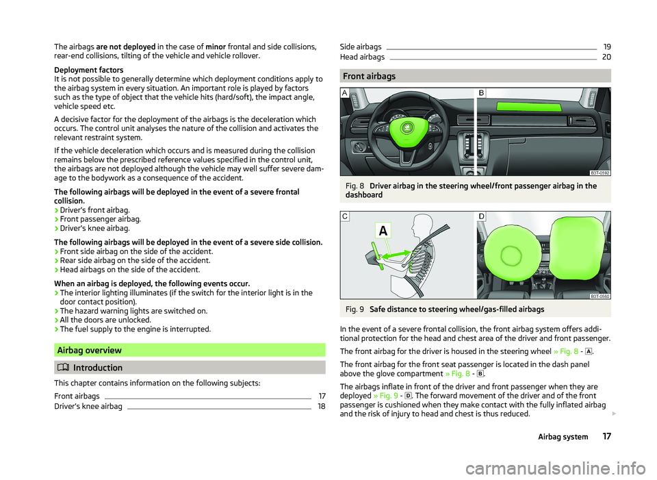
Front airbags
Fig. 8
Driver airbag in the steering wheel/front passenger airbag in the
dashboard
Fig. 9
Safe distance to steering wheel/gas-filled airbags
In the event of a severe frontal collision, the front airbag system offers addi-
tional protection for the head and chest area of the driver and front passenger.
The front airbag for the driver is housed in the steering wheel » Fig. 8 -
.
The front airbag for the front seat passenger is located in the dash panel
above the glove compartment » Fig. 8 -
.
The airbags inflate in front of the driver and front passenger when they are
deployed » Fig. 9 -
. The forward movement of the driver and of the front
passenger is cushioned when they make contact with the fully inflated airbag
and the risk of injury to head and chest is thus reduced.
17Airbag system
Page 21 of 252

WARNINGInformation on correct seated position■For the driver and front passenger, it is important to maintain a distance
of at least 25 cm from the steering wheel or dashboard A
» Fig. 9 . Not
maintaining this minimum distance will mean that the airbag system will
not be able to properly protect you - hazard! The front seats and the head
restraints must always also be correctly adjusted to match the body size of
the occupant.
■
The airbag develops enormous forces when triggered, which can lead to
injuries if the sitting position or seated position is not correct.
■
There must not by any further persons, animals or objects positioned be-
tween the front seated occupants and the deployment area of the airbag.
WARNINGFront airbag and transporting children■Never transport children on the front seat of a vehicle without using a
proper restraint system. If airbags are deployed in the event of an accident,
the child might suffer severe or even fatal injuries!■
The front passenger airbag must be deactivated if using a rear-facing
child seat on the front passenger seat » page 20, Deactivating airbags . If
this is not done, there is a risk of the child suffering severe or even fatal
injuries if the front passenger airbag is deployed. When transporting a child
on the front passenger seat, pay attention to any relevant national regula-
tions regarding the use of child safety seats.
WARNINGGeneral information■The steering wheel and the surface of the airbag module in the dash pan-
el on the passenger side must not have stickers attached, be covered or
modified in any other way. These parts should only be cleaned with a cloth
that is dry or has been moistened with water. No objects such as cup hold-
ers, mobile phone mounts, etc. must be attached to the covers of the air-
bag modules or be located within their immediate vicinity.■
Never place objects on the surface of the front passenger airbag module
in the dash panel.
Note■ In vehicles with head airbags, the lettering can be seen on the steering
wheel.■
In vehicles with front passenger airbags, the lettering
is located on the
dash panel on the passenger side.
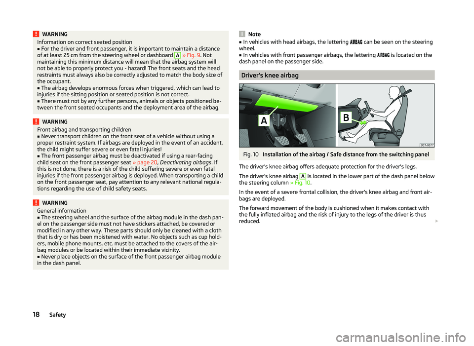
Driver’s knee airbag
Fig. 10
Installation of the airbag / Safe distance from the switching panel
The driver's knee airbag offers adequate protection for the driver's legs.
The driver's knee airbag
A
is located in the lower part of the dash panel below
the steering column » Fig. 10.
In the event of a severe frontal collision, the driver's knee airbag and front air-
bags are deployed.
The forward movement of the body is cushioned when it makes contact with
the fully inflated airbag and the risk of injury to the legs of the driver is thus
reduced.
18Safety
Page 173 of 252

Distance of the centre of gravity ofthe load from the ball headPermissible total weight of the ac- cessory, including load0 cm80 kg30 cm75 kg60 cm35 kg70 cm0 kgWARNING■Never exceed the permissible gross weight of the accessory including
load - there is a risk of damaging the ball head of the towing hitch.■
Never exceed the permissible overhang of the ball head of the towing
hitch - there is a risk of damaging the ball head of the towing hitch.
Note
We recommend that you use accessories from ŠKODA Original Accessories.
Trailer
Introduction
This chapter contains information on the following subjects:
Attaching and detaching trailers
170
Loading a trailer
171
Towing a trailer
171
Trailer stabilisation (TSA)
172
Anti-theft alarm system
172
If your vehicle has already been factory fitted with towing equipment or is fit-
ted with towing equipment from ŠKODA Original Accessories, then it meets all
of the technical requirements and national legal provisions for towing a trailer.
Note
If there is an error in the trailer lighting system, check the fuses in the fuse box
in the dashboard » page 220.Attaching and detaching trailersFig. 161
Swivel out the 13-pin power
socket, safety eyelet
Coupling
›
Install the tow bar.
›
Grip the 13-pin socket at point
A
and swing out in the direction of ar-
row » Fig. 161 .
›
Lift off protective cap
5
» Fig. 155 on page 167 towards the top.
›
Place the trailer onto the ball.
›
Insert the trailer cable into the 13-pin socket.
If the trailer that is to be towed has a 7-pin connector, you can use a suitable
adapter from ŠKODA Original Accessories to establish a connection to the elec-
tricity.
›
Hook the breakaway cable of the trailer to the security lock slot
B
.
The breakaway cable of the trailer has to sag when mounted into the security
lock slot for all trailer positions relative to the vehicle (sharp curves, reverse
driving and the like).
Uncoupling
The uncoupling of the trailer is carried out in reverse order.
›
Unhook the breakaway cable of the trailer from the security lock slot
B
» Fig. 161 .
›
Pull the trailer cable out of the 13-pin socket.
›
Remove the trailer from the ball head.
›
Place the cover
5
on the ball head » Fig. 155 on page 167 .
›
Grip the 13-pin socket at point
A
and swing in the opposite direction to the
arrow » Fig. 161 .
170Driving
Page 213 of 252

Tyre inflation pressure indicator
Air release valve
ON and OFF switch
12 volt cable connector
Tyre inflator bottle with sealing agent
Replacement valve core
The valve remover 1
has a slot at its lower end which fits into the valve core.
The kit is located in a box under the floor covering in the luggage compart-
ment. This contains a sealing means and an air compressor.
Note
The declaration of conformity is included with the air compressor or the log
folder.
Preparations for using the breakdown kit
Read and observe
on page 209 first.
The following preparatory work must be carried out before using the puncturerepair kit.
›
Have all the occupants get out. The passengers should not stand on the
road (instead they should remain behind a crash barrier, for instance) while
the wheel is being changed.
›
Switch off the engine.
›
Select the 1st gear or place the selector lever of the automatic transmission
in the P-position .
›
Apply the handbrake firmly.
›
Check that you can carry out the repairs with the breakdown kit
» page 209.
›
Uncouple a trailer.
›
Remove the breakdown kit from the boot.
›
Stick the appropriate sticker
2
» Fig. 183 on page 209 onto the dashboard in
the driver's field of view.
›
Unscrew the valve cap.
›
Use the valve remover
1
to unscrew the valve core and place it on a clean
surface (rag, paper, etc.).
67891011Sealing and inflating the tyre
Read and observe
on page 209 first.
Sealing
›
Shake the tyre inflator bottle
10
» Fig. 183 on page 209 vigorously several
times.
›
Firmly screw the inflation hose
3
onto the tyre inflator bottle
10
in a clock-
wise direction. The film on the cap is pierced automatically.
›
Remove the plug from the inflation hose
3
and plug the open end fully onto
the tyre valve.
›
Hold the bottle
10
with the bottom facing upwards and fill all of the sealing
agent from the tyre inflator bottle into the tyre.
›
Remove the empty tyre inflator bottle from the valve.
›
Screw the valve core back into the tyre valve using the valve remover
1
.
Inflating
›
Screw the air compressor tyre inflation hose
5
» Fig. 183 on page 209 firmly
onto the tyre valve.
›
Check that the air release valve
7
is closed.
›
Start the engine and run it in idle.
›
Plug the connector
9
into 12 Volt socket » page 91, Cigarette lighter .
›
Switch on the air compressor with the ON and OFF switch
8
.
›
Allow the air compressor to run until a pressure of 2.0 - 2.5 bar is achieved.
Maximum run time of 8 minutes » .
›
Switch off the air compressor.
›
If you cannot reach an air pressure of 2.0 - 2.5 bar, unscrew the tyre inflation
hose
5
from the tyre valve.
›
Drive the vehicle 10 metres forwards or backwards to allow the sealing agent
to “distribute” in the tyre.
›
Firmly screw the tyre inflation hose
5
back onto the tyre valve and repeat
the inflation process.
›
If you cannot reach the required tyre inflation pressure here either, this
means the tyre has sustained too much damage. You cannot seal with tyre with the breakdown kit »
.
›
Switch off the air compressor.
›
Remove the tyre inflation hose
5
from the tyre valve.
Once a tyre pressure of 2.0 - 2.5 bar is reached, the journey may be continued
at a maximum speed of 80 km/h (50 mph).
210Do-it-yourself