clutch SKODA SUPERB 2010 Owner´s Manual
[x] Cancel search | Manufacturer: SKODA, Model Year: 2010, Model line: SUPERB, Model: SKODA SUPERB 2010Pages: 252, PDF Size: 16.33 MB
Page 10 of 252
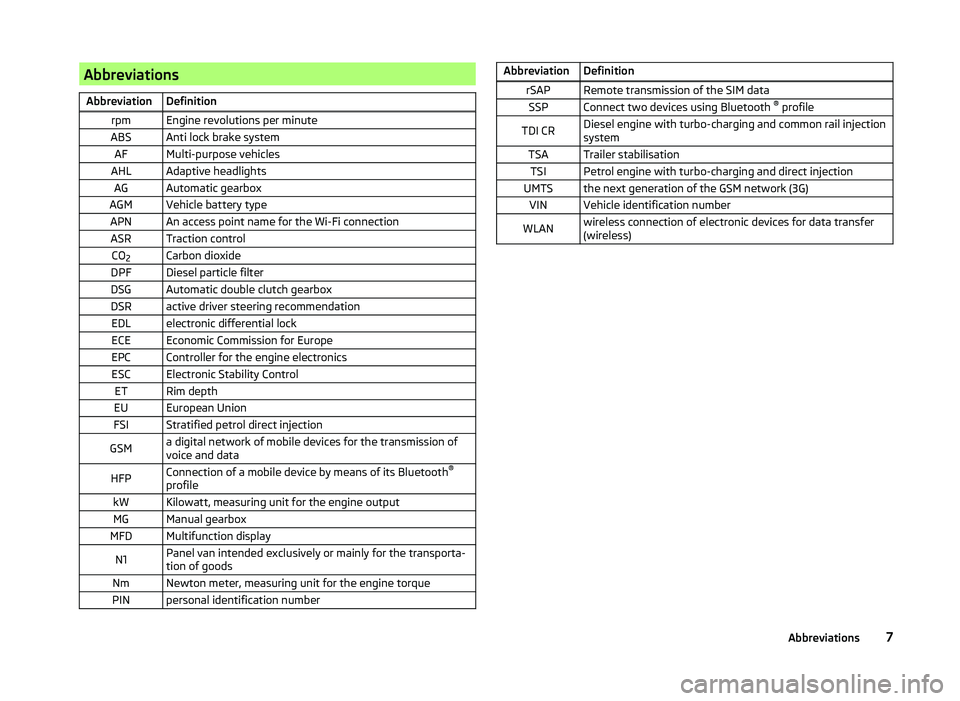
AbbreviationsAbbreviationDefinitionrpmEngine revolutions per minuteABSAnti lock brake systemAFMulti-purpose vehiclesAHLAdaptive headlightsAGAutomatic gearboxAGMVehicle battery typeAPNAn access point name for the Wi-Fi connectionASRTraction controlCO2Carbon dioxideDPFDiesel particle filterDSGAutomatic double clutch gearboxDSRactive driver steering recommendationEDLelectronic differential lockECEEconomic Commission for EuropeEPCController for the engine electronicsESCElectronic Stability ControlETRim depthEUEuropean UnionFSIStratified petrol direct injectionGSMa digital network of mobile devices for the transmission of
voice and dataHFPConnection of a mobile device by means of its Bluetooth ®
profilekWKilowatt, measuring unit for the engine outputMGManual gearboxMFDMultifunction displayN1Panel van intended exclusively or mainly for the transporta-
tion of goodsNmNewton meter, measuring unit for the engine torquePINpersonal identification numberAbbreviationDefinitionrSAPRemote transmission of the SIM dataSSPConnect two devices using Bluetooth ®
profileTDI CRDiesel engine with turbo-charging and common rail injection
systemTSATrailer stabilisationTSIPetrol engine with turbo-charging and direct injectionUMTSthe next generation of the GSM network (3G)VINVehicle identification numberWLANwireless connection of electronic devices for data transfer
(wireless)7Abbreviations
Page 13 of 252
WARNING■Always assume the correct seated position before setting off and do not
change this position while driving. Also advise your passengers to adopt
the correct seated position and not to change this position while the car is
moving.■
Maintain a distance of at least 25 cm from the steering wheel, and a dis-
tance of at least 10 cm between the legs and the dash panel at the height
of the knee airbag. Not maintaining this minimum distance will mean that
the airbag system will not be able to properly protect you - hazard!
■
When driving, hold the steering wheel with both hands firmly on the out-
er edge in the “9 o'clock” and “3 o'clock” position. Never hold the steering
wheel in the “12 o'clock” position or in any other way (e.g. in the middle or
inner edge of the steering wheel). In such cases, you could severely injure
your arms, hands and head when the driver airbag is deployed.
■
Ensure that there are no objects in the driver's footwell, as these may get
caught in the pedal apparatus when driving or braking. You would then no
longer be able to operate the clutch, brake or acceleration pedals.
Adjusting the steering wheel position
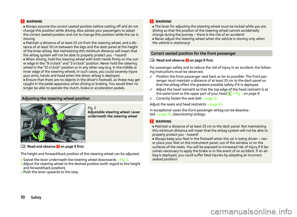
Fig. 2
Adjustable steering wheel: Lever
underneath the steering wheel
Read and observe on page 9 first.
The height and forward/back position of the steering wheel can be adjusted.
›
Swivel the lever underneath the steering wheel downwards » Fig. 2.
›
Adjust the steering wheel to the desired position (with regard to the height
and forward/back position).
›
Push the lever upwards to the stop.
WARNING■ The lever for adjusting the steering wheel must be locked while you are
driving so that the position of the steering wheel cannot accidentally
change during the journey – there is the risk of an accident!■
Never adjust the steering wheel when the vehicle is moving only when
the vehicle is stationary!
Correct seated position for the front passenger
Read and observe
on page 9 first.
For passenger safety and to reduce the risk of injury in an accident, the follow-ing instructions must be observed.
Position the front passenger seat back as far as possible. The front pas-
senger must maintain a distance of at least 25 cm to the dash panel so
that the airbag offers the greatest possible safety if it is deployed.
Adjust the head restraint so that the top edge of the head restraint is at
the same level as the upper part of your head
C
» Fig. 1 on page 9 .
Correctly fasten the seat belt » page 12.
Adjust the seats and head restraints » page 81.
In exceptional cases the front passenger airbag can be deactiva-
ted » page 20 , Deactivating airbags .
WARNING■
Maintain a distance of at least 25 cm to the dash panel. Not maintaining
this minimum distance will mean that the airbag system will not be able to
properly protect you - hazard!■
Always keep your feet in the footwell when the car is being driven – nev-
er place your feet on the instrument panel, out of the window or on the
surfaces of the seats. You will be exposed to increased risk of injury if it be-
comes necessary to apply the brake or in the event of an accident. If an air-
bag is deployed, you could suffer fatal injuries by adopting an incorrect
seated position!
10Safety
Page 36 of 252
Display of the second speedRead and observe
on page 30 first.
The display can show the current speed in mph 1)
.
This feature is provided for driving in countries with different units for speed.
MAXI DOT display
The display of the second speed can be set in the Alt. speed dis. menu
item » page 47 , Settings .
Segment display
›
Press the
3
» Fig. 21 on page 30 key repeatedly, until the odometer display
flashes » page 32 .
›
Press the
7
key while the display is flashing.
The second speed is displayed instead of the odometer.
Display of the second speed can be disabled in the same way.
Display in rear centre console
Fig. 26
Centre console at rear: Display
Read and observe on page 30 first.
The time and the outside temperature are displayed on the display in the rear
centre console when the ignition is switched on » Fig. 26.
The values are taken over by the instrument cluster.
Auto Check Control
Read and observe
on page 30 first.
Vehicle condition
Certain functions and conditions of individual vehicle systems are checked
continuously when the ignition is switched on.
Some error messages and other information are displayed in the MAXI DOT
display. The messages are displayed simultaneously with the icons in the MAXI
DOT display or with the warning lights in the instrument cluster » page 34,
Warning lights .
The Vehicle status menu item is shown in the main menu of the MAXI DOT
display whenever at least one fault message is present. The first of the fault
messages is displayed after this menu item is selected. Several error messages
are shown on the display under the message e.g. 1/3. This indicates that the
first of a total of three error messages is being displayed.
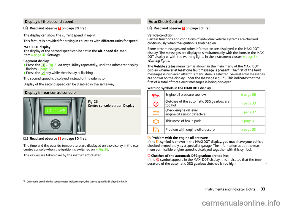
Warning symbols in the MAXI DOT display
Engine oil pressure too low» page 36Clutches of the automatic DSG gearbox are
too hot» page 33Check engine oil level,
engine oil sensor defective» page 37Thickness of brake pads» page 41Problem with engine oil pressure» page 33
Problem with the engine oil pressure
If the symbol is shown in the MAXI DOT display, you must have your vehicle
checked immediately by a specialist garage. The information about the maxi-
mum permissible engine speed is displayed together with this symbol.
Clutches of the automatic DSG gearbox are too hot
If the symbol appears in the MAXI DOT display, this indicates that the tem-
perature of the automatic DSG gearbox clutches is too high.
1)
On models on which the speedometer indicates mph, the second speed is displayed in km/h.
33Instruments and Indicator Lights
Page 92 of 252
Storage compartment under the front armrest92Storage net in front centre console93
Glasses storage box
93
Storage compartment on passenger side
94
Storage compartment under passenger seat
94
Clothes hook
94
Storage pockets on the front seats
95
Storage compartment for umbrella
95
Storage compartment in rear centre console
95
Storage compartment in the rear armrest
96
Rear seat backrest with long cargo channel
96
Removable ski bag
97WARNING■Do not place anything on the dash panel. These objects might slide or fall
down while you are driving (under acceleration or when cornering) and
could distract you from the traffic - there is a risk of an accident.■
Make sure that no objects from the centre console or from other storage
compartments can get into the driver's footwell while you are driving. You
would not be able to brake, operate the clutch pedal or accelerate - danger
of causing an accident!
■
No objects should be placed in the storage compartments nor in the
drinks holders; the vehicle occupants could be endangered if there is sud-
den braking or the vehicle collides with something.
■
Ash and cigarette or cigar stubs must only be discarded in ashtrays.
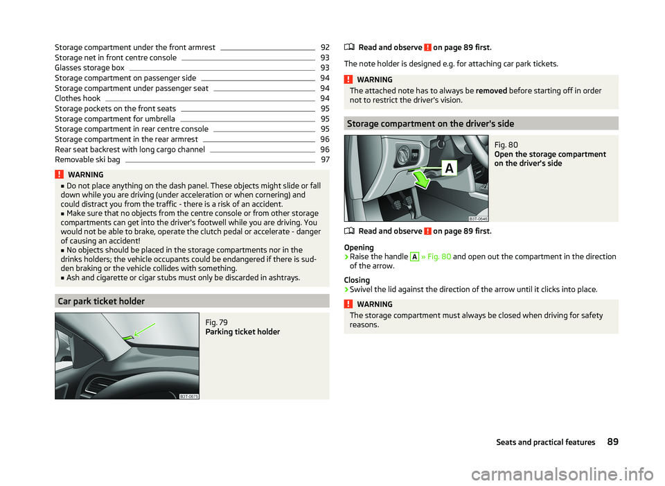
Car park ticket holder
Fig. 79
Parking ticket holder
Read and observe on page 89 first.
The note holder is designed e.g. for attaching car park tickets.
WARNINGThe attached note has to always be removed before starting off in order
not to restrict the driver's vision.
Storage compartment on the driver's side
Fig. 80
Open the storage compartment
on the driver's side
Read and observe on page 89 first.
Opening
›
Raise the handle
A
» Fig. 80 and open out the compartment in the direction
of the arrow.
Closing
›
Swivel the lid against the direction of the arrow until it clicks into place.
WARNINGThe storage compartment must always be closed when driving for safety
reasons.89Seats and practical features
Page 142 of 252
Electronic immobilizerRead and observe
and on page 138 first.
An electronic chip is integrated in the head of the key. The immobiliser is deac-
tivated with the aid of this chip when the key is inserted in the ignition lock.
The electronic immobiliser is automatically activated when the ignition key is
withdrawn from the lock.
The engine will not start if a non-authorized ignition key is used.
The following message is shown in the instrument cluster display. Immobilizer active.
IMMOBILIZER
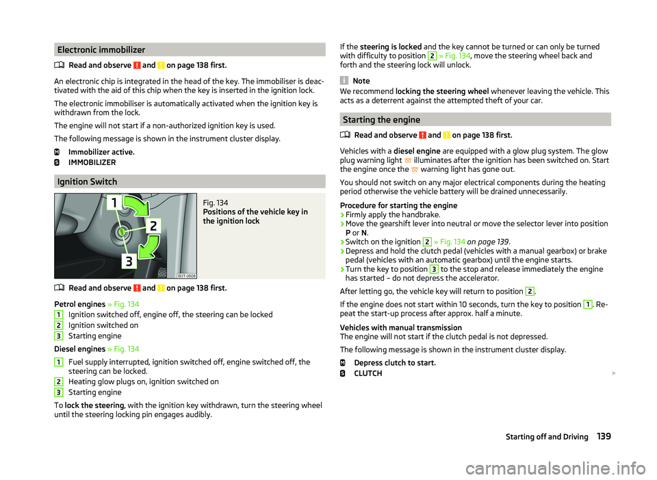
Ignition Switch
Fig. 134
Positions of the vehicle key in
the ignition lock
Read and observe and on page 138 first.
Petrol engines » Fig. 134
Ignition switched off, engine off, the steering can be locked
Ignition switched on
Starting engine
Diesel engines » Fig. 134
Fuel supply interrupted, ignition switched off, engine switched off, the
steering can be locked.
Heating glow plugs on, ignition switched on
Starting engine
To lock the steering , with the ignition key withdrawn, turn the steering wheel
until the steering locking pin engages audibly.
123123If the steering is locked and the key cannot be turned or can only be turned
with difficulty to position 2 » Fig. 134 , move the steering wheel back and
forth and the steering lock will unlock.
Note
We recommend locking the steering wheel whenever leaving the vehicle. This
acts as a deterrent against the attempted theft of your car.
Starting the engine
Read and observe
and on page 138 first.
Vehicles with a diesel engine are equipped with a glow plug system. The glow
plug warning light illuminates after the ignition has been switched on. Start
the engine once the warning light has gone out.
You should not switch on any major electrical components during the heating
period otherwise the vehicle battery will be drained unnecessarily.
Procedure for starting the engine
›
Firmly apply the handbrake.
›
Move the gearshift lever into neutral or move the selector lever into position
P or N.
›
Switch on the ignition
2
» Fig. 134 on page 139 .
›
Depress and hold the clutch pedal (vehicles with a manual gearbox) or brake
pedal (vehicles with an automatic gearbox) until the engine starts.
›
Turn the key to position
3
to the stop and release immediately the engine
has started – do not depress the accelerator.
After letting go, the vehicle key will return to position
2
.
If the engine does not start within 10 seconds, turn the key to position
1
. Re-
peat the start-up process after approx. half a minute.
Vehicles with manual transmission
The engine will not start if the clutch pedal is not depressed.
The following message is shown in the instrument cluster display. Depress clutch to start.
CLUTCH
139Starting off and Driving
Page 144 of 252
CAUTION■Avoid high engine revolutions, full throttle and high engine loads before the
engine has reached its operating temperature – risk of damaging the engine!■
Do not switch the engine off immediately at the end of your journey after the
engine has been operated over a prolonged period at high loads but leave it to
run at an idling speed for about 1 minute. This prevents any possible accumula-
tion of heat when the engine is switched off.
For the sake of the environment
Do not warm up the engine while the vehicle is stationary. If possible, start
your journey as soon as the engine has started. Through this the engine rea-
ches its operating temperature more rapidly and the pollutant emissions are
lower.
Note
■ The system is protected against inadvertently switching off the engine while
driving, this means that the engine can only be switched off in an emergen-
cy » page 143 .■
After switching off the ignition, the radiator fan can intermittently continue
to operate for approx. 10 minutes.
■
Under certain circumstances (e.g. after switching off the ignition and opening
the driver's door), the steering is enabled only when the ignition is switched on
or the engine is started.
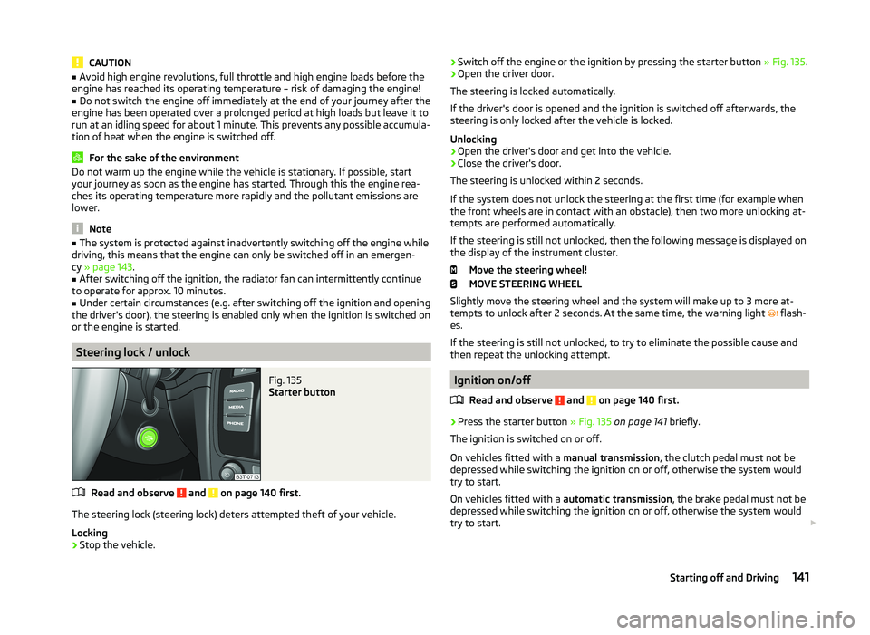
Steering lock / unlock
Fig. 135
Starter button
Read and observe and on page 140 first.
The steering lock (steering lock) deters attempted theft of your vehicle.
Locking
›
Stop the vehicle.
› Switch off the engine or the ignition by pressing the starter button
» Fig. 135.›Open the driver door.
The steering is locked automatically.
If the driver's door is opened and the ignition is switched off afterwards, the
steering is only locked after the vehicle is locked.
Unlocking›
Open the driver's door and get into the vehicle.
›
Close the driver's door.
The steering is unlocked within 2 seconds.
If the system does not unlock the steering at the first time (for example when
the front wheels are in contact with an obstacle), then two more unlocking at-
tempts are performed automatically.
If the steering is still not unlocked, then the following message is displayed on the display of the instrument cluster.
Move the steering wheel!
MOVE STEERING WHEEL
Slightly move the steering wheel and the system will make up to 3 more at-
tempts to unlock after 2 seconds. At the same time, the warning light flash-
es.
If the steering is still not unlocked, to try to eliminate the possible cause and
then repeat the unlocking attempt.
Ignition on/off
Read and observe
and on page 140 first.
›
Press the starter button » Fig. 135 on page 141 briefly.
The ignition is switched on or off.
On vehicles fitted with a manual transmission, the clutch pedal must not be
depressed while switching the ignition on or off, otherwise the system would
try to start.
On vehicles fitted with a automatic transmission, the brake pedal must not be
depressed while switching the ignition on or off, otherwise the system would
try to start.
141Starting off and Driving
Page 145 of 252
If the driver's door is opened while the ignition is on, an audible signal sounds
and the following message appears in the instrument cluster display.
Ignition on!
IGNITION SWITCHED ON
When leaving the vehicle always switch off the ignition.
Note
The ignition is switched on when indicated by the illuminating of certain indi-
cator lamps in the instrument cluster.
Starting the engine
Read and observe
and on page 140 first.
Vehicles with a diesel engine are equipped with a glow plug system. The glow
plug warning light illuminates after the ignition has been switched on. Start
the engine once the warning light has gone out.
You should not switch on any major electrical components during the heating
period otherwise the vehicle battery will be drained unnecessarily.
Procedure for starting the engine
›
Firmly apply the handbrake.
›
Move the gearshift lever into neutral or move the selector lever into position
P or N.
›
Depress and hold the clutch pedal (vehicles with a manual gearbox) or brake
pedal (vehicles with an automatic gearbox) until the engine starts.
›
Press and hold » Fig. 135 on page 141 1)
the starter button until the engine
starts.
CAUTION
■ If the engine does not start-up after a second attempt, one of the following
fuses may be defective. ■ Petrol engine - fuse for the electric fuel pump.
■ Diesel engine - fuse for the control unit for glow plugs or glow plug relay
and fuel pump.■
Check the fuse and replace if necessary » page 220, or seek assistance from
a specialist garage.
Switching off the engine
Read and observe
and on page 140 first.
›
Stop the vehicle.
›
Press the starter button » Fig. 135 on page 141 briefly.
The engine and the ignition are switched off simultaneously.
The engine can be switched off up to a speed of 2 km/h.
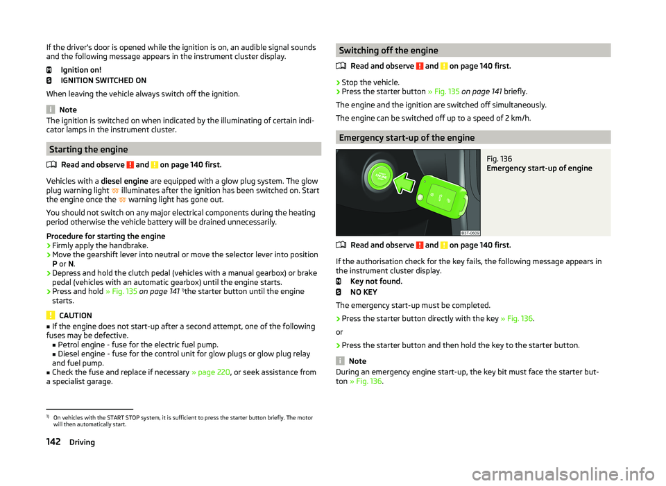
Emergency start-up of the engine
Fig. 136
Emergency start-up of engine
Read and observe and on page 140 first.
If the authorisation check for the key fails, the following message appears in the instrument cluster display.
Key not found.
NO KEY
The emergency start-up must be completed.
› Press the starter button directly with the key
» Fig. 136.
or
› Press the starter button and then hold the key to the starter button.
Note
During an emergency engine start-up, the key bit must face the starter but-
ton » Fig. 136 .1)
On vehicles with the START STOP system, it is sufficient to press the starter button briefly. The motor
will then automatically start.
142Driving
Page 146 of 252
Emergency ignition shutoff systemRead and observe
and on page 140 first.
The ignition can be turned off in an emergency even when travelling at a
speed of more than 2 km / hr.
›
Press the starter button » Fig. 135 on page 141 for longer than 1 second or
twice within 1 second.
After emergency stop of the ignition, the steering is unlocked.
Brakes
Introduction
This chapter contains information on the following subjects:
Information on braking
143
Handbrake
144WARNING■ Greater physical effort is required for braking when the engine is switch-
ed off – risk of accident!■
The clutch pedal must be depressed when braking on a vehicle with man-
ual transmission, when the vehicle is in gear and at low revs. Otherwise,
the function of the brake booster may be impaired – risk of accident!
■
When leaving the vehicle, never leave persons who might, for example,
release the handbrake or take the vehicle out of gear unattended in the ve-
hicle. The vehicle could then start to move – risk of accident!
WARNINGIn the case of damage to the standard fitted front spoiler or if retrofitting
another front spoiler, hub caps etc. » page 173, Services, modifications and
technical alterations , make sure that the air supply to the front brakes is
not affected. The front brakes may overheat, which can have a negative im-
pact on the functioning of the braking system – there is a risk of an acci-
dent!CAUTION■ Observe the recommendations on the new brake pads » page 149.■Never let the brakes slip with light pressure on the pedal if braking is not
necessary. This causes the brakes to overheat and can also result in a longer
braking distance and excessive wear.
Information on braking
Read and observe
and on page 143 first.
If the brakes are applied in full and the control unit for the braking system con-siders the situation to be dangerous for the following traffic, the brake light
flashes automatically.
After the speed was reduced below around 10 km/h or the vehicle was stop-
ped, the brake light stops flashing and the hazard warning light system
switches on. The hazard warning light system is switched off automatically af- ter accelerating or driving off again.
Before travelling a long distance down a steep gradient, reduce speed and
shift into the next lowest gear. As a result, the braking effect of the engine will
be used, reducing the load on the brakes. Any additional braking should be
completed intermittently, not continuously.
Wear-and-tear
The wear of the brake pads is dependent on the operating conditions and driv- ing style.
The brake pads wear more quickly if a lot of journeys are completed in towns
and over short distances or if a very sporty style of driving is adopted.
Under these severe conditions , the thickness of the brake pads must also be
checked by a specialist garage between services.
Wet roads or road salt
The performance of the brakes can be delayed as the brake discs and brake
pads may be moist or have a coating of ice or layer of salt on them in winter.
The brakes are cleaned and dried by applying the brakes several times.
Corrosion
Corrosion on the brake discs and dirt on the brake pads occur if the vehicle has
been parked for a long period and if you do not make much use of the braking
system. The brakes are cleaned by applying the brakes several times.
143Starting off and Driving
Page 147 of 252
Faults in the brake surface
If it is found that the braking distance has suddenly become longer and that
the brake pedal can be depressed further, the brake system may be faulty.
Visit a specialist garage immediately and adjust your style of driving appropri-
ately as you will not know the exact extent of the damage.
Low brake fluid level
An insufficient level of brake fluid may result in problems in the brake system.
The level of the brake fluid is monitored electronically » page 35,
Brake sys-
tem .
Brake booster
The brake booster increases the pressure generated with the brake pedal. The
brake booster only operates when the engine is running.
Handbrake
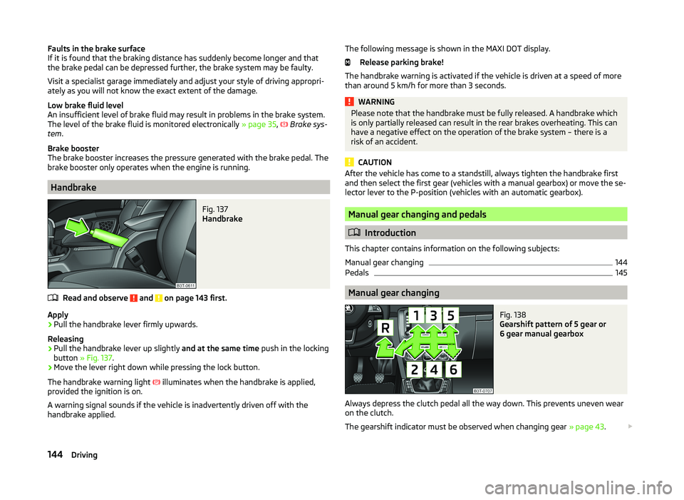
Fig. 137
Handbrake
Read and observe and on page 143 first.
Apply
›
Pull the handbrake lever firmly upwards.
Releasing
›
Pull the handbrake lever up slightly and at the same time push in the locking
button » Fig. 137 .
›
Move the lever right down while pressing the lock button.
The handbrake warning light illuminates when the handbrake is applied,
provided the ignition is on.
A warning signal sounds if the vehicle is inadvertently driven off with the
handbrake applied.
The following message is shown in the MAXI DOT display.
Release parking brake!
The handbrake warning is activated if the vehicle is driven at a speed of more
than around 5 km/h for more than 3 seconds.WARNINGPlease note that the handbrake must be fully released. A handbrake which
is only partially released can result in the rear brakes overheating. This can
have a negative effect on the operation of the brake system – there is a
risk of an accident.
CAUTION
After the vehicle has come to a standstill, always tighten the handbrake first
and then select the first gear (vehicles with a manual gearbox) or move the se-
lector lever to the P-position (vehicles with an automatic gearbox).
Manual gear changing and pedals
Introduction
This chapter contains information on the following subjects:
Manual gear changing
144
Pedals
145
Manual gear changing
Fig. 138
Gearshift pattern of 5 gear or
6 gear manual gearbox
Always depress the clutch pedal all the way down. This prevents uneven wear on the clutch.
The gearshift indicator must be observed when changing gear » page 43.
144Driving
Page 148 of 252
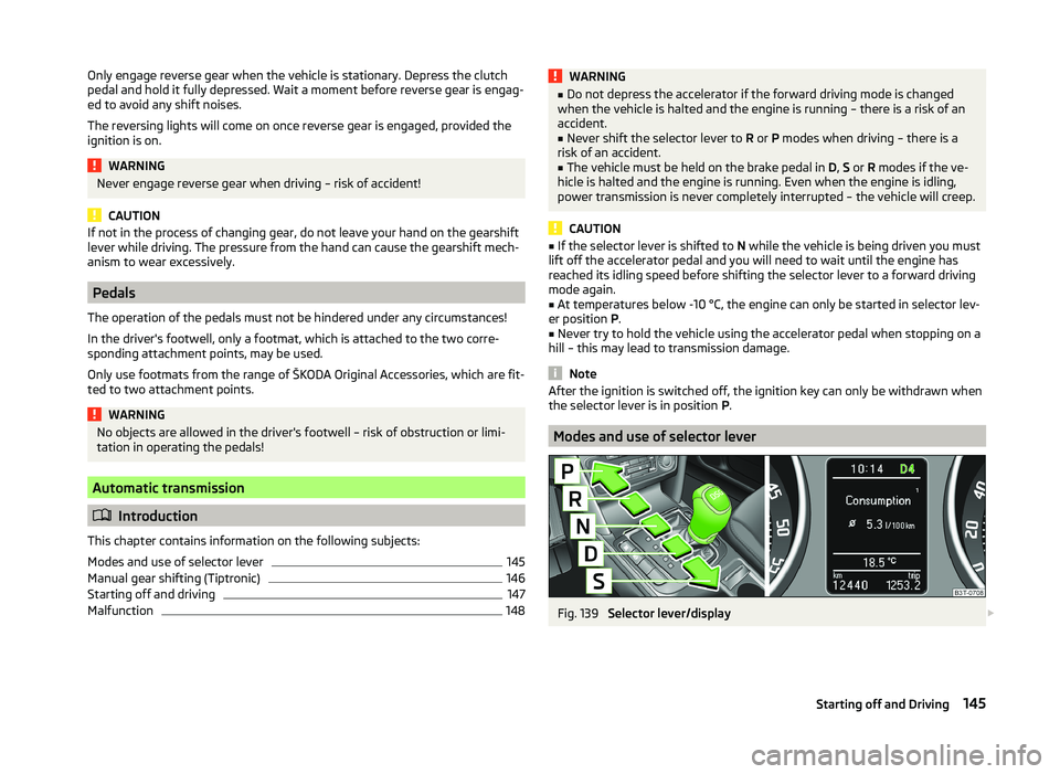
Only engage reverse gear when the vehicle is stationary. Depress the clutch
pedal and hold it fully depressed. Wait a moment before reverse gear is engag-
ed to avoid any shift noises.
The reversing lights will come on once reverse gear is engaged, provided the
ignition is on.WARNINGNever engage reverse gear when driving – risk of accident!
CAUTION
If not in the process of changing gear, do not leave your hand on the gearshift
lever while driving. The pressure from the hand can cause the gearshift mech-
anism to wear excessively.
Pedals
The operation of the pedals must not be hindered under any circumstances!
In the driver's footwell, only a footmat, which is attached to the two corre-
sponding attachment points, may be used.
Only use footmats from the range of ŠKODA Original Accessories, which are fit-
ted to two attachment points.
WARNINGNo objects are allowed in the driver's footwell – risk of obstruction or limi-
tation in operating the pedals!
Automatic transmission
Introduction
This chapter contains information on the following subjects:
Modes and use of selector lever
145
Manual gear shifting (Tiptronic)
146
Starting off and driving
147
Malfunction
148WARNING■ Do not depress the accelerator if the forward driving mode is changed
when the vehicle is halted and the engine is running – there is a risk of an
accident.■
Never shift the selector lever to R or P modes when driving – there is a
risk of an accident.
■
The vehicle must be held on the brake pedal in D, S or R modes if the ve-
hicle is halted and the engine is running. Even when the engine is idling,
power transmission is never completely interrupted – the vehicle will creep.
CAUTION
■ If the selector lever is shifted to N while the vehicle is being driven you must
lift off the accelerator pedal and you will need to wait until the engine has
reached its idling speed before shifting the selector lever to a forward driving
mode again.■
At temperatures below -10 °C, the engine can only be started in selector lev-
er position P.
■
Never try to hold the vehicle using the accelerator pedal when stopping on a
hill – this may lead to transmission damage.
Note
After the ignition is switched off, the ignition key can only be withdrawn when
the selector lever is in position P.
Modes and use of selector lever
Fig. 139
Selector lever/display
145Starting off and Driving