fuse box SKODA SUPERB 2010 Owner´s Manual
[x] Cancel search | Manufacturer: SKODA, Model Year: 2010, Model line: SUPERB, Model: SKODA SUPERB 2010Pages: 252, PDF Size: 16.33 MB
Page 145 of 252
If the driver's door is opened while the ignition is on, an audible signal sounds
and the following message appears in the instrument cluster display.
Ignition on!
IGNITION SWITCHED ON
When leaving the vehicle always switch off the ignition.
Note
The ignition is switched on when indicated by the illuminating of certain indi-
cator lamps in the instrument cluster.
Starting the engine
Read and observe
and on page 140 first.
Vehicles with a diesel engine are equipped with a glow plug system. The glow
plug warning light illuminates after the ignition has been switched on. Start
the engine once the warning light has gone out.
You should not switch on any major electrical components during the heating
period otherwise the vehicle battery will be drained unnecessarily.
Procedure for starting the engine
›
Firmly apply the handbrake.
›
Move the gearshift lever into neutral or move the selector lever into position
P or N.
›
Depress and hold the clutch pedal (vehicles with a manual gearbox) or brake
pedal (vehicles with an automatic gearbox) until the engine starts.
›
Press and hold » Fig. 135 on page 141 1)
the starter button until the engine
starts.
CAUTION
■ If the engine does not start-up after a second attempt, one of the following
fuses may be defective. ■ Petrol engine - fuse for the electric fuel pump.
■ Diesel engine - fuse for the control unit for glow plugs or glow plug relay
and fuel pump.■
Check the fuse and replace if necessary » page 220, or seek assistance from
a specialist garage.
Switching off the engine
Read and observe
and on page 140 first.
›
Stop the vehicle.
›
Press the starter button » Fig. 135 on page 141 briefly.
The engine and the ignition are switched off simultaneously.
The engine can be switched off up to a speed of 2 km/h.
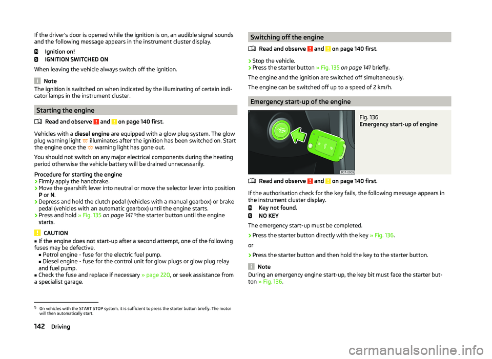
Emergency start-up of the engine
Fig. 136
Emergency start-up of engine
Read and observe and on page 140 first.
If the authorisation check for the key fails, the following message appears in the instrument cluster display.
Key not found.
NO KEY
The emergency start-up must be completed.
› Press the starter button directly with the key
» Fig. 136.
or
› Press the starter button and then hold the key to the starter button.
Note
During an emergency engine start-up, the key bit must face the starter but-
ton » Fig. 136 .1)
On vehicles with the START STOP system, it is sufficient to press the starter button briefly. The motor
will then automatically start.
142Driving
Page 151 of 252
WARNINGRapid acceleration, particularly on slippery roads, can lead to loss of control
of the vehicle – there is a risk of an accident.
Malfunction
Read and observe
and on page 145 first.
Emergency programme
The transmission switches to the emergency programme if there is a fault in
the automatic gearbox system.
Indications of an activated emergency programme include the following:
› Only certain gears are selected.
› Reverse gear
R cannot be used.
› Shifting gears in Tiptronic mode is not possible.
Gearbox overheating
The gearbox may, for example, become too hot due to frequent repeated
starting or stop-and-go traffic. Overheating is indicated by the warning
light » page 33 ,
Clutches of the automatic DSG gearbox are too hot
.
Defective selector lever lock
If the selector lever lock is defective or its power supply is interrupted (e.g. dis-
charged vehicle battery, faulty fuse), the selector lever can no longer be moved
out of position P in the normal manner, and the vehicle can no longer be driv-
en. The selector lever must be emergency released » page 217.
Note
Visit a specialist workshop if the gearbox has switched to the emergency pro-
gramme.
Running in
Introduction
This chapter contains information on the following subjects:
New engine
148
New tyres
149
New brake pads
149New engine
The engine has to be run in during the first 1 500 kilometres.
Up to 1,000 kilometres›
Do not drive faster than 3/4 of the maximum speed of the gear in use, which
means 3/4 of the maximum permissible engine speed.
›
No full throttle.
›
Avoid high engine speeds.
›
Do not tow a trailer.
From 1,000 up to 1,500 kilometres
Gradually increase the power output of the engine up to the full speed of the
gear engaged, which means up to the maximum permissible engine speed.
The red scale on the rev counter indicates the range in which the system be-
gins to limit the engine speed.
During the first operating hours the engine has higher internal friction than
later until all of the moving parts have harmonized. The driving style which you
adopt during the first approx.1 500 kilometres plays a decisive part in the suc-
cess of running in your car.
Never drive at unnecessarily high engine speeds even after the running in pe-
riod.
On vehicles fitted with a manual gearbox, at the very latest shift up into the
next gear when the red area is reached. Observe the recommended
gear » page 43 , Gear recommendation . Very high engine speeds when acceler-
ating (accelerator) are automatically restricted »
.
In vehicles with manual transmission, do not drive at unnecessarily low engine
speeds. Shift down a gear when the engine is no longer running smoothly. Ob-
serve the recommended gear » page 43, Gear recommendation .
CAUTION
■
The engine is not protected from excessive engine revs caused by shifting
down at the wrong time. This can result in a sudden increase in revs beyond
the permissible maximum rpm and hence engine damage.■
Never rev up a cold engine when the vehicle is stationary or when driving in
individual gears.
For the sake of the environment
Do not drive at unnecessarily high engine speeds. Shifting up sooner helps
save fuel, reduces engine noise and protects the environment.148Driving
Page 173 of 252

Distance of the centre of gravity ofthe load from the ball headPermissible total weight of the ac- cessory, including load0 cm80 kg30 cm75 kg60 cm35 kg70 cm0 kgWARNING■Never exceed the permissible gross weight of the accessory including
load - there is a risk of damaging the ball head of the towing hitch.■
Never exceed the permissible overhang of the ball head of the towing
hitch - there is a risk of damaging the ball head of the towing hitch.
Note
We recommend that you use accessories from ŠKODA Original Accessories.
Trailer
Introduction
This chapter contains information on the following subjects:
Attaching and detaching trailers
170
Loading a trailer
171
Towing a trailer
171
Trailer stabilisation (TSA)
172
Anti-theft alarm system
172
If your vehicle has already been factory fitted with towing equipment or is fit-
ted with towing equipment from ŠKODA Original Accessories, then it meets all
of the technical requirements and national legal provisions for towing a trailer.
Note
If there is an error in the trailer lighting system, check the fuses in the fuse box
in the dashboard » page 220.Attaching and detaching trailersFig. 161
Swivel out the 13-pin power
socket, safety eyelet
Coupling
›
Install the tow bar.
›
Grip the 13-pin socket at point
A
and swing out in the direction of ar-
row » Fig. 161 .
›
Lift off protective cap
5
» Fig. 155 on page 167 towards the top.
›
Place the trailer onto the ball.
›
Insert the trailer cable into the 13-pin socket.
If the trailer that is to be towed has a 7-pin connector, you can use a suitable
adapter from ŠKODA Original Accessories to establish a connection to the elec-
tricity.
›
Hook the breakaway cable of the trailer to the security lock slot
B
.
The breakaway cable of the trailer has to sag when mounted into the security
lock slot for all trailer positions relative to the vehicle (sharp curves, reverse
driving and the like).
Uncoupling
The uncoupling of the trailer is carried out in reverse order.
›
Unhook the breakaway cable of the trailer from the security lock slot
B
» Fig. 161 .
›
Pull the trailer cable out of the 13-pin socket.
›
Remove the trailer from the ball head.
›
Place the cover
5
on the ball head » Fig. 155 on page 167 .
›
Grip the 13-pin socket at point
A
and swing in the opposite direction to the
arrow » Fig. 161 .
170Driving
Page 223 of 252
Fuses and light bulbs
Fuses
Introduction
This chapter contains information on the following subjects:
Fuses in the dash panel
220
Fuses in the engine compartment
222
Assignment of fuses in the engine compartment
222
Individual electrical circuits are protected by fuses.
Switch off the ignition and the corresponding power consuming device before
replacing a fuse.
Find out which fuse belongs to the component that is not operat-
ing » page 220 , Fuses in the dash panel or » page 222 , Assignment of fuses in
the engine compartment .
Electrically adjustable seats are protected by automatic circuit breakers, which
switch on again automatically after a few seconds after the overload has been
eliminated.
Fuse colourMaximum amperagelight brown5dark brown7.5red10blue15yellow20white25green30orange40red50WARNINGAlways read and observe the warnings before completing any work in the
engine compartment » page 186.CAUTION■
“Never repair” fuses or replace them with a fuse of a higher amperage –
there is a risk of fire. This may also cause damage at another part of the elec-
trical system.■
A blown fuses is recognisable by the molten metal strip. Replace the faulty
fuse with a new one of the same amperage.
■
If a newly inserted fuse burns through again, then a specialist should be con-
sulted immediately.
Note
■ We recommend always carrying replacement fuses in the vehicle. A box of
replacement fuses can be purchased from ŠKODA Original Accessories.■
There can be multiple power consuming devices for one fuse.
■
A single consumer may use several fuses.
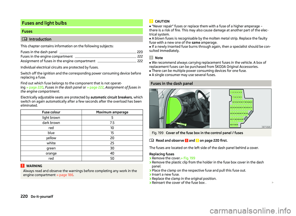
Fuses in the dash panel
Fig. 199
Cover of the fuse box in the control panel / fuses
Read and observe
and on page 220 first.
The fuses are located on the left side of the dash panel behind a cover.
Replacing fuses
›
Remove the cover. » Fig. 199
›
Remove the plastic clip from the holder in the fuse box cover in the dash
panel.
›
Place the clamp on the respective fuse and pull this fuse out.
›
Insert a new fuse.
›
Replace the clamp in the original position.
›
Reinsert the cover of the fuse box .
220Do-it-yourself
Page 225 of 252
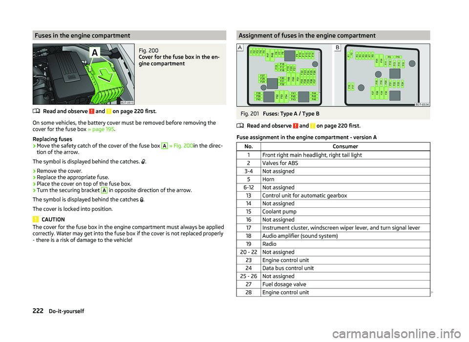
Fuses in the engine compartmentFig. 200
Cover for the fuse box in the en-
gine compartment
Read and observe and on page 220 first.
On some vehicles, the battery cover must be removed before removing the
cover for the fuse box » page 195.
Replacing fuses
›
Move the safety catch of the cover of the fuse box
A
» Fig. 200 in the direc-
tion of the arrow.
The symbol is displayed behind the catches. .
›
Remove the cover.
›
Replace the appropriate fuse.
›
Place the cover on top of the fuse box.
›
Turn the securing bracket
A
in opposite direction of the arrow.
The symbol is displayed behind the catches .
The cover is locked into position.
CAUTION
The cover for the fuse box in the engine compartment must always be applied
correctly. Water may get into the fuse box if the cover is not replaced properly
- there is a risk of damage to the vehicle!Assignment of fuses in the engine compartmentFig. 201
Fuses: Type A / Type B
Read and observe
and on page 220 first.
Fuse assignment in the engine compartment - version A
No.Consumer1Front right main headlight, right tail light2Valves for ABS3-4Not assigned5Horn6-12Not assigned13Control unit for automatic gearbox14Not assigned15Coolant pump16Not assigned17Instrument cluster, windscreen wiper lever, and turn signal lever18Audio amplifier (sound system)19Radio20 - 22Not assigned23Engine control unit24Data bus control unit25 - 26Not assigned27Fuel dosage valve28Engine control unit 222Do-it-yourself
Page 226 of 252
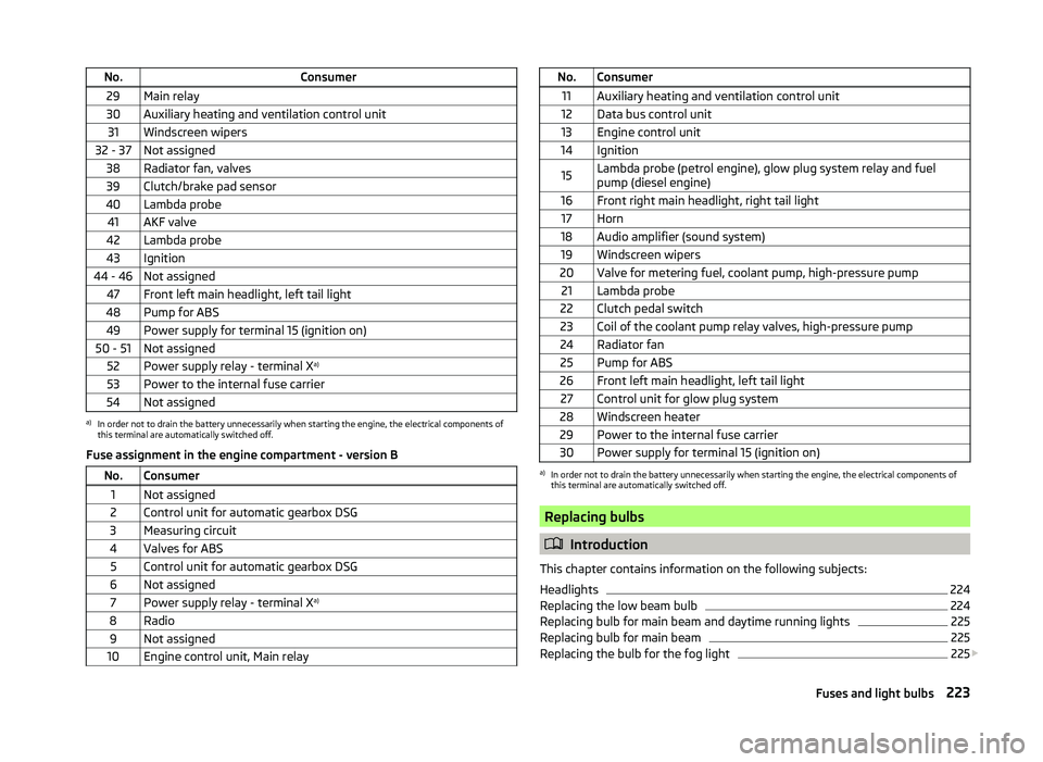
No.Consumer29Main relay30Auxiliary heating and ventilation control unit31Windscreen wipers32 - 37Not assigned38Radiator fan, valves39Clutch/brake pad sensor40Lambda probe41AKF valve42Lambda probe43Ignition44 - 46Not assigned47Front left main headlight, left tail light48Pump for ABS49Power supply for terminal 15 (ignition on)50 - 51Not assigned52Power supply relay - terminal Xa)53Power to the internal fuse carrier54Not assigneda)
In order not to drain the battery unnecessarily when starting the engine, the electrical components of
this terminal are automatically switched off.
Fuse assignment in the engine compartment - version B
No.Consumer1Not assigned2Control unit for automatic gearbox DSG3Measuring circuit4Valves for ABS5Control unit for automatic gearbox DSG6Not assigned7Power supply relay - terminal X a)8Radio9Not assigned10Engine control unit, Main relayNo.Consumer11Auxiliary heating and ventilation control unit12Data bus control unit13Engine control unit14Ignition15Lambda probe (petrol engine), glow plug system relay and fuel
pump (diesel engine)16Front right main headlight, right tail light17Horn18Audio amplifier (sound system)19Windscreen wipers20Valve for metering fuel, coolant pump, high-pressure pump21Lambda probe22Clutch pedal switch23Coil of the coolant pump relay valves, high-pressure pump24Radiator fan25Pump for ABS26Front left main headlight, left tail light27Control unit for glow plug system28Windscreen heater29Power to the internal fuse carrier30Power supply for terminal 15 (ignition on)a)
In order not to drain the battery unnecessarily when starting the engine, the electrical components of
this terminal are automatically switched off.
Replacing bulbs
Introduction
This chapter contains information on the following subjects:
Headlights
224
Replacing the low beam bulb
224
Replacing bulb for main beam and daytime running lights
225
Replacing bulb for main beam
225
Replacing the bulb for the fog light
225
223Fuses and light bulbs
Page 242 of 252
Selector lever-unlocking217
Sliding/tilting roof218
Start engine - KESSY142
Switching off the ignition –KESSY143
Towing the vehicle213
Towing the vehicle using the tow hitch214
tyre repair209
Unlocking the boot lid217
Unlocking the driver's door216
Emergency equipment Fire extinguisher
204
First-aid kit 204
Jack205
Vehicle tool kit205
Warning triangle204
Emissions229
Engine Running in
148
Engine compartment186
Brake fluid193
Coolant191
Overview188
Vehicle battery193
Engine number228
Engine oil189
Capacity189
Checking190
Note messages36
Replenishing191
Specifications189
Engine oil level Warning light
37
Engine oil pressure Warning light
36
Entry lighting75
Environment149
Environmental compatibility151
Environmentally friendly driving149
EPC Warning light
39
ESCFunction154
Warning light37
Exhaust inspection system Warning light
38
Extendable variable loading floor Fixing set
106
Extending variable loading floor105
Divide boot105
Movable lashing eyes107
Partial extension105
F
Fastening elements
99
Fatigue detection165
Function165
Information messages165
Films179
Fire extinguisher204
First-aid kit 204
Floor covering Fixing
100
Fog lights71
Warning light41
Fog lights with CORNER function71
Folding hook99
Fold in passenger's mirror80
Footmats145
see Footmats145
Force limit Electric boot lid (Superb Combi)
59
Power windows63
Sliding/tilting roof64
Sliding/tilting roof (Superb Combi)66
Front airbag17
Front door warning light74
Front interior light73
Fuel183
Diesel185
Fuel gauge32
refer to Fuel183
Refuelling184
Unleaded petrol184
Fuel consumption149, 229
Fuel reserve Warning light
39
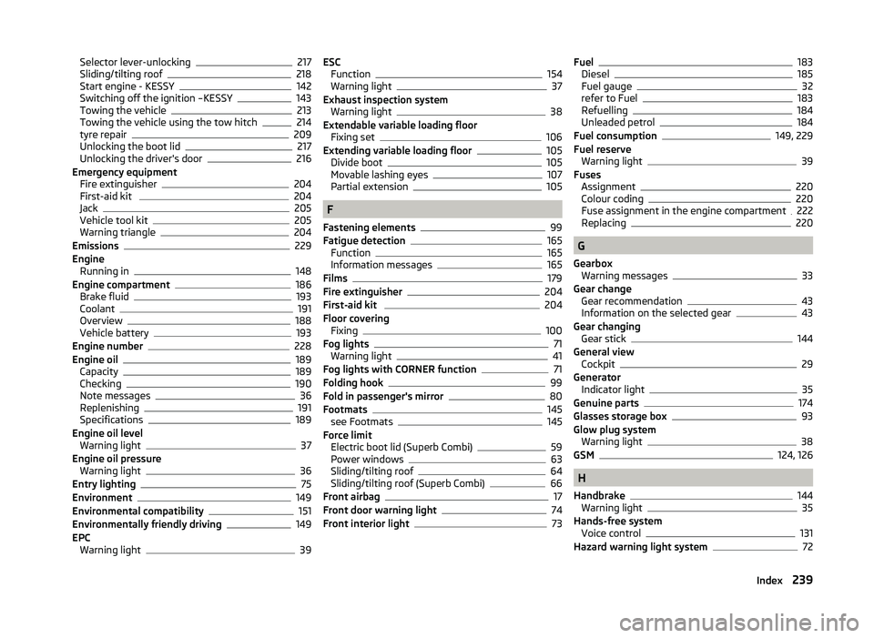
Fuses Assignment
220
Colour coding220
Fuse assignment in the engine compartment222
Replacing220
G
Gearbox Warning messages
33
Gear change Gear recommendation
43
Information on the selected gear43
Gear changing Gear stick
144
General view Cockpit
29
Generator Indicator light
35
Genuine parts174
Glasses storage box93
Glow plug system Warning light
38
GSM124, 126
H
Handbrake
144
Warning light35
Hands-free system Voice control
131
Hazard warning light system72
239Index
Page 245 of 252
Park Assistautomatic emergency braking160
Operation158
Parking Park assist
157
Parking aid156
Parking aid156
Function157
Parking light68
Part replacement173
Passive safety Before setting off
8
Driving safety8
Safety equipment8
Passive Safety8
Payload229
Pedals145
Footmats145
Petrol refer to Fuel
184
Polishing the paintwork See Taking care of your vehicle
178
Power outlet 12 V
92
Power Steering / steering lock (KESSY system) warning light
36
Power windows Button in the front passenger door
63
Practical features88
12 Volt power outlet92
Ashtray91
Car park ticket holder89
Cigarette lighter91
Clothes hook94
Cup holders90
Glasses storage box93
Removable ski bag97
Seat backrest with long cargo channel96
Storage compartment for umbrella95
Storage compartment in rear centre console95
Storage compartment in the front centre con- sole90
Storage compartment on passenger side94
Storage compartment on the driver's side89
Storage compartments in the doors90
Storage compartment under passenger seat94
Storage compartment under the front armrest 92
Storage net in front centre console
93
Storage pockets on the front seats95
Puncture set209
R
Radiator fan
188
Radio4
Radio reception See windows
179
Radio remote control Auxiliary heating
120
Raise vehicle207
Rear-view mirror Exterior mirrors
80
Fold in passenger mirror80
Synchronous adjustment of the rear-view mir- ror
80
Rear fog light71
Warning light38
Rear interior light74
Rear mirror79
Interior mirror79
Rear seats Seat folded forward Combi
88
Rear window - heater75
Recirculated air mode Manual air conditioning
114
Refuelling184
Fuel184
Remote control Locking
52
Replacing the battery215
Synchronisation process215
Unlocking52
Remote control key Replacing the battery
215
Removable lights (Superb Combi) Changing rechargeable light batteries
103
Removable Light (Superb Combi) Remove light
103
Removable ski bag97
Removable variable loading floor Fit and remove
106
Repairs and technical alterations173
Replacing Bulb for main beam
225
Bulb for main beam and daytime running lights 225
Bulb for the fog light
225
Bulb for the licence plate light226
Bulb in rear light (Superb Combi)227
Fuses220
Fuses in the dash panel220
Fuses in the engine compartment222
Low beam bulb224
Vehicle battery196
Wiper blades219
Replenishing Coolant
192
Engine oil191
Windscreen washer fluid188
Revolution counter31
Roof luggage rack Attachment points
109
Roof rack108
Roof rack system Roof load
109
Running in Brake pads
149
Engine148
The first 1,500 km148
Tyres149
242Index