spare wheel SKODA SUPERB 2010 Owner´s Manual
[x] Cancel search | Manufacturer: SKODA, Model Year: 2010, Model line: SUPERB, Model: SKODA SUPERB 2010Pages: 252, PDF Size: 16.33 MB
Page 103 of 252
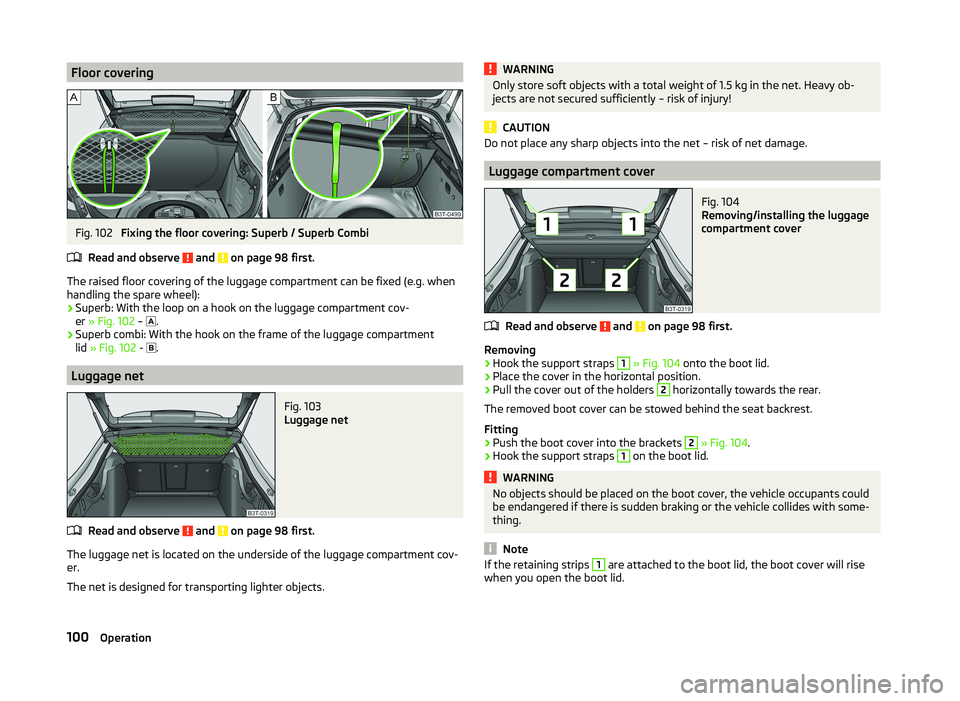
Floor coveringFig. 102
Fixing the floor covering: Superb / Superb Combi
Read and observe
and on page 98 first.
The raised floor covering of the luggage compartment can be fixed (e.g. when
handling the spare wheel):
› Superb: With the loop on a hook on the luggage compartment cov-
er » Fig. 102 –
.
› Superb combi: With the hook on the frame of the luggage compartment
lid » Fig. 102 -
.
Luggage net
Fig. 103
Luggage net
Read and observe and on page 98 first.
The luggage net is located on the underside of the luggage compartment cov-
er.
The net is designed for transporting lighter objects.
WARNINGOnly store soft objects with a total weight of 1.5 kg in the net. Heavy ob-
jects are not secured sufficiently – risk of injury!
CAUTION
Do not place any sharp objects into the net – risk of net damage.
Luggage compartment cover
Fig. 104
Removing/installing the luggage
compartment cover
Read and observe and on page 98 first.
Removing
›
Hook the support straps
1
» Fig. 104 onto the boot lid.
›
Place the cover in the horizontal position.
›
Pull the cover out of the holders
2
horizontally towards the rear.
The removed boot cover can be stowed behind the seat backrest.
Fitting
›
Push the boot cover into the brackets
2
» Fig. 104 .
›
Hook the support straps
1
on the boot lid.
WARNINGNo objects should be placed on the boot cover, the vehicle occupants could
be endangered if there is sudden braking or the vehicle collides with some-
thing.
Note
If the retaining strips 1 are attached to the boot lid, the boot cover will rise
when you open the boot lid.100Operation
Page 161 of 252
The parking aid is part of the park assist system, therefore the information
and safety guidelines » page 156 , Parking aid must also be read and ob-
served.WARNING■ The system only serves as an assistance and does not relieve the driver
of the responsibility for the vehicle operation.■
During the parking process, the system automatically performs rapid
steering movements. While it is doing so, do not place your hands between
the steering wheel spokes – risk of injury!
■
During a parking manoeuvre on loose or slippery surfaces (gravel, snow,
ice, etc.) you may stray from the calculated road because of the surface
conditions. Therefore we suggest that you do not use the system in such
situations.
■
External noise sources may affect the signals of the system sensors. Un-
der adverse conditions, this may cause objects or people to not be recog-
nised by the system.
CAUTION
■ If other vehicles are parked behind the kerb or on it, the system can also
guide your vehicle beyond the kerb or onto it. Ensure that the wheels or the
wheel rims of your vehicle are not damaged and if necessary intervene in time.■
Under certain circumstances, surfaces or structures of certain objects such
as wire mesh fences or powder snow cannot be recognised by the system.
■
Under adverse weather conditions (heavy rain, water vapour, very low or
high temperatures etc.), the system function may be limited - “incorrect recog-
nition of obstacle”.
CAUTION
The correct evaluation of the parking space and the parking procedure de-
pends on the circumference of the wheels on the vehicle.■
The system only works correctly if the vehicle is fitted with the wheel size
approved by the manufacturer.
■
Do without the use of the system if snow chains or a spare wheel is moun-
ted.
■
If wheels other than those approved by the manufacturer are mounted, the
resulting position of the vehicle in the parking space can differ slightly. This
can be avoided by readjusting the system at a specialist garage.
Note
We recommend performing the parking at a safe speed to about 5 km / h.Functioning
Read and observe
and on page 158 first.
Basic system operations
› The measurement and evaluation of the size of parking spaces when driving.
› The determination of the correct position of the vehicle for parking.
› The calculation of the line on which the vehicle drives backwards into the
parking space or forwards from the parking space.
› Automatic rotation of the front wheels during the parking.
The display of the instrument cluster (hereinafter only in the display) informa- tion and system messages are displayed.
When the system is activated, the warning light illuminates
» Fig. 149 on
page 158 -
.
The traction control system (ASR) must always be switched on when parking.
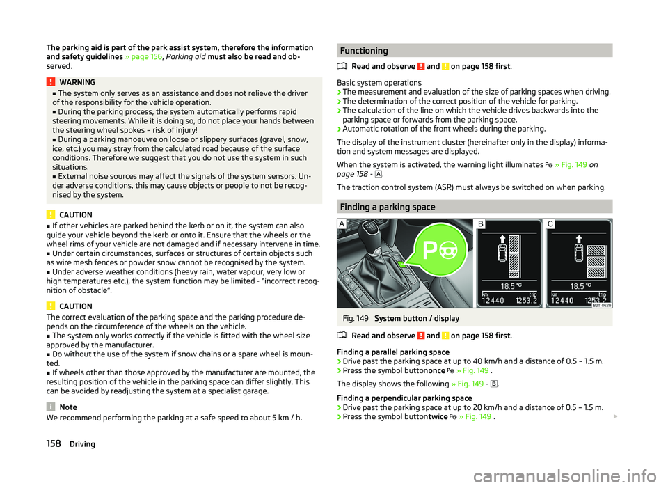
Finding a parking space
Fig. 149
System button / display
Read and observe
and on page 158 first.
Finding a parallel parking space
›
Drive past the parking space at up to 40 km/h and a distance of 0.5 – 1.5 m.
›
Press the symbol button once
» Fig. 149 .
The display shows the following » Fig. 149 -
.
Finding a perpendicular parking space
›
Drive past the parking space at up to 20 km/h and a distance of 0.5 – 1.5 m.
›
Press the symbol button twice
» Fig. 149 .
158Driving
Page 170 of 252

DescriptionFig. 155
Carrier for the towing device / tow bar
Read and observe
and on page 166 first.
The ball head can be removed and is kept in the spare wheel well or in a com-
partment for the spare wheel in the luggage compartment.
Support for the towing device and tow bar » Fig. 155
13-pin power socket
Safety eyelet
Mounting recess
Cap
Dust cap
Ball head
Operating lever
Lock cap
Release pin
Key
locking ball
Note
If you lose the key, please get in touch with a specialist garage.1234567891011Adjusting the ready positionFig. 156
Setting the ready position/ready position
Read and observe
and on page 166 first.
The coupling ball bar must be set prior to installation in the standby position.
If this is not in the ready position, then this must be set to the standby posi-
tion as follows.
›
Grip the ball head below the protective cap
2
.
›
Remove the cap from the lock.
›
Insert the key into the lock, so that its green marking is pointing upwards.
›
Turn key
1
in direction of the arrow, so that the red marking is facing up-
wards » Fig. 156 .
›
Press the release pin
3
as far as the stop in the direction of the arrow and
at the same time push the lever
4
downwards as far as it will go in the di-
rection of the arrow.
The operating lever remains locked in this position.
CAUTION
In the ready position, the key cannot be removed nor turned to a different po-
sition.167Hitch and trailer
Page 200 of 252

NoteWe recommend having the vehicle checked by a specialist garage in order to
ensure full functionality of all electrical systems.
Automatic load deactivation
Read and observe
and on page 194 first.
The vehicle voltage control unit automatically prevents the battery from dis-
charging when the battery is put under high levels of strain. This may be no-
ticed from the following.
› The idling speed is raised to allow the generator to deliver more electricity to
the electrical system.
› Where necessary, large convenience consumers such as seat heaters and
rear window heaters have their power limited or are shut off completely in
the event of an emergency.
CAUTION
■ Despite such intervention by the vehicle electric system management, the
vehicle battery may be drained. For example, when the ignition is switched on
a long time with the engine turned off or the side or parking lights are turned
on during longer parking.■
Consumers that are supplied via a 12-V power socket can cause the vehicle
battery to discharge when the ignition is switched off.
Note
Driving comfort is not impaired by consumers being deactivated. The driver is
often not aware of it having taken place.Wheels
Tyres and wheel rims
Introduction
This chapter contains information on the following subjects:
Service life of tyres
198
Unidirectional tyres
199
Spare and temporary spare wheel
200
Full wheel trim
200
Wheel bolts
201
Only use tyres or wheel rims that have been approved by ŠKODA for your mod-
el of vehicle.
WARNINGThe national legal regulations must be observed for the use of tyres.WARNINGInstructions for the use of tyres■For the first 500 km, new tyres do not yet provide optimum grip, and ap-
propriate care should therefore be taken when driving – risk of accident!■
For reasons of driving safety, do not replace tyres individually.
■
Never exceed the maximum permissible load bearing capacity of moun-
ted tyres.
■
Never exceed the maximum permissible speed for the mounted tyres.
■
An incorrect wheel alignment at the front or rear impairs handling.
■
Unusual vibrations or pulling of the vehicle to one side could be a sign of
tyre damage. If there is any doubt that a wheel is damaged, immediately re-
duce your speed and stop! If no external damage is evident, drive slowly
and carefully to the nearest specialist garage to have the vehicle checked.
WARNINGInformation regarding tyre damage or wear■Never use tyres if you do not know anything about the condition and age.■
Never drive with damaged tyres – there is the risk of an accident occur-
ring.
197Wheels
Page 201 of 252
WARNING (Continued)■You must have your tyres replaced with new ones at the latest when the
wear indicators have been worn down.■
Worn tyres impair necessary adhesion to the road surface, particularly at
high speeds on wet roads. This could lead to “aquaplaning” (uncontrolled
vehicle movement – “swimming” on a wet road surface).
WARNING■ Having the correct tyre inflation pressure is always the driver's responsi-
bility.■
Too low or too high inflation pressure impairs handling.
■
If the inflation pressure is too low, the tyre will have to overcome a higher
rolling resistance. This will cause a significant increase in the temperature
of the tyre, especially at higher speeds. This can result in tread separation
and a tyre blowout.
■
In the event of very fast tyre inflation pressure loss, such as a sudden tyre
failure, an attempt should be made to bring the vehicle carefully to a stop
without sudden steering movements and without any hard braking.
CAUTION
■ If a spare wheel is used that is not identical to the fitted tyres, the following
must be observed » page 200, Spare and temporary spare wheel .■
The tyres must be protected from contact with substances such as oil,
grease and fuel, which could damage them. If the tyres come into contact with
these substances, then we recommend you have this checked out in a special-
ist workshop.
■
If, in the case of puncture occurring, the spare tyre with a non-bound direc-
tion or an opposite direction of rotation must be mounted, then drive carefully.
The best properties of the tyre are no longer present in this situation.
For the sake of the environment
■ Old and unserviceable tyres are classified in a special environmentally haz-
ardous category. These must be disposed of in accordance with national legis-
lation.■
Tyres that are insufficiently inflated increase your fuel consumption.
Note
■ We recommend that any work on the wheels or tyres be carried out by a spe-
cialist garage.■
We recommend that you use wheel rims, tyres, full wheel trims and snow
chains from ŠKODA Original Accessories.
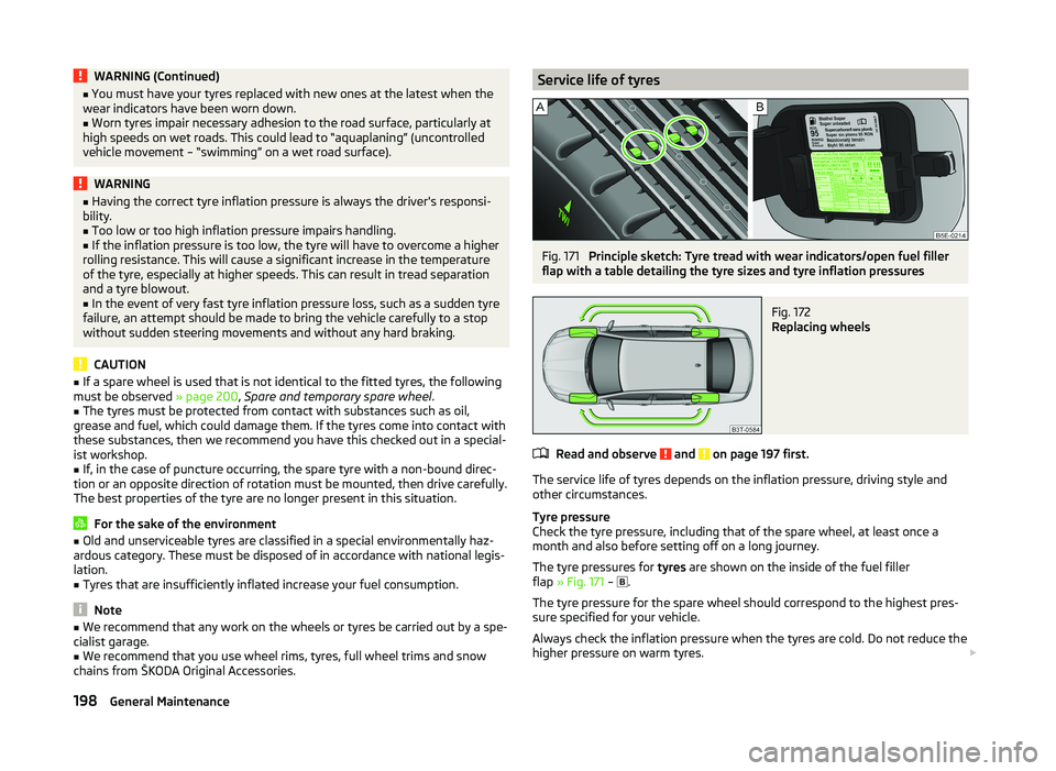
Service life of tyresFig. 171
Principle sketch: Tyre tread with wear indicators/open fuel filler
flap with a table detailing the tyre sizes and tyre inflation pressures
Fig. 172
Replacing wheels
Read and observe and on page 197 first.
The service life of tyres depends on the inflation pressure, driving style and
other circumstances.
Tyre pressure
Check the tyre pressure, including that of the spare wheel, at least once a
month and also before setting off on a long journey.
The tyre pressures for tyres are shown on the inside of the fuel filler
flap » Fig. 171 –
.
The tyre pressure for the spare wheel should correspond to the highest pres-
sure specified for your vehicle.
Always check the inflation pressure when the tyres are cold. Do not reduce the
higher pressure on warm tyres.
198General Maintenance
Page 203 of 252
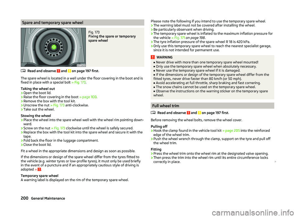
Spare and temporary spare wheelFig. 173
Fixing the spare or temporary
spare wheel
Read and observe and on page 197 first.
The spare wheel is located in a well under the floor covering in the boot and is fixed in place with a special bolt » Fig. 173.
Taking the wheel out
›
Open the boot lid.
›
Raise the floor covering in the boot » page 100.
›
Remove the box with the tool kit.
›
Unscrew the nut » Fig. 173 anti-clockwise.
›
Take out the wheel.
Stowing the wheel
›
Place the wheel into the spare wheel well with the wheel rim pointing down-
ward.
›
Screw on the nut » Fig. 173 clockwise until the wheel is safely secured.
›
Replace the box with the tool kit into the spare wheel and secure it with the
tape.
›
Fold back the floor in the luggage compartment.
›
Close the boot lid.
Fit a wheel in the appropriate dimensions and design as soon as possible.
If the dimensions or design of the spare wheel differ from the tyres fitted to
the vehicle (e.g. winter tyres or low-profile tyres), it must only be used briefly
in the event of a puncture and if an appropriately cautious style of driving is
adopted »
.
Temporary spare wheel
A warning label is displayed on the rim of the temporary spare wheel.
Please note the following if you intend to use the temporary spare wheel.
› The warning label must not be covered after installing the wheel.
› Be particularly observant when driving.
› The temporary spare wheel is inflated to the maximum inflation pressure for
the vehicle » Fig. 171 on page 198 .
› The tyre inflation pressure of the spare wheel R 18 is 420 kPa.
› Only use this temporary spare wheel to reach the nearest specialist garage,
since it is not intended for permanent use.WARNING■ Never drive with more than one temporary spare wheel mounted!■Only use the temporary spare wheel when absolutely necessary.■
Never use the temporary spare wheel if it is damaged.
■
If the dimensions or design of the temporary spare wheel differ from the
fitted tyres, never drive faster than 80 km/h (or 50 mph).
■
Avoid accelerating at full throttle, sharp braking and fast cornering.
■
The snow chains cannot be used on the temporary spare wheel.
■
Observe the instructions on the warning sticker on the temporary spare
wheel.
Full wheel trim
Read and observe
and on page 197 first.
Before removing the wheel bolts, remove the wheel cover.
Pulling off
›
Hook the clamp found in the vehicle tool kit » page 205 into the reinforced
edge of the wheel trim.
›
Push the wheel wrench through the clamp, support on the tyre and pull off
the wheel trim.
Fitting
›
Press the wheel trim onto the wheel rim at the designated valve opening.
›
Then press the trim into the wheel rim until its entire circumference locks
correctly in place.
200General Maintenance
Page 208 of 252
The fire extinguisher must be checked by an authorised person once a year.
National legal requirements must be observed.WARNINGThe fire extinguisher must always be secured safely so that they do not
come loose when making an emergency braking or in a vehicle collision
which could cause injuries to occupants.
Note
■ The fire extinguisher must comply with national legal requirements.■Pay attention to the expiration date of the fire extinguisher. Proper function-
ing of the fire extinguisher is not assured once it has passed its expiry date.■
The fire extinguisher is part of the scope of delivery in certain countries only.
Vehicle tool kit
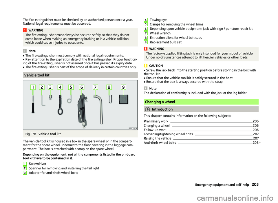
Fig. 178
Vehicle tool kit
The vehicle tool kit is housed in a box in the spare wheel or in the compart-
ment for the spare wheel underneath the floor covering in the luggage com-
partment. The box is attached with a strap on the spare wheel.
Depending on the equipment, not all the components listed in the on-board
tool kit have to be contained in it.
Screwdriver
Spanner for removing and installing the tail light
Adapter for anti-theft wheel bolts
123Towing eye
Clamps for removing the wheel trims
Depending upon vehicle equipment: Jack with sign / puncture repair kit
Wheel wrench
Extraction pliers for wheel bolt caps
Replacement bulb setWARNINGThe factory-supplied lifting jack is only intended for your model of vehicle.
Under no circumstances attempt to lift heavier vehicles or other loads.
CAUTION
■ Screw the jack back into the starting position before storing in the box with
the tool kit.■
Ensure that the vehicle tool kit is safely secured in the boot.
■
Ensure that the box is always secured with the strap.
Note
The declaration of conformity is included with the jack or the log folder.
Changing a wheel
Introduction
This chapter contains information on the following subjects:
Preliminary work
206
Changing a wheel
206
Follow-up work
206
Loosening/tightening wheel bolts
207
Raising the vehicle
207
Anti-theft wheel bolts
208
456789205Emergency equipment and self-help
Page 209 of 252
WARNING■If you are in flowing traffic, switch on the hazard warning light system
and set up the warning triangle at the prescribed distance! The national le-
gal requirements must be observed.■
Park the vehicle as far away as possible from the flow of traffic. Park on
as flat and firm a surface as possible.
■
The following instructions must be followed if the vehicle is subsequently
fitted with tyres or rims that differ from the factory fitted ones » page 201,
Explanation of the tyre labelling .
WARNINGInformation on the wheel bolts■The wheel bolts must be clean and must turn easily. Never treat them
with grease or oil.■
The prescribed tightening torque of the wheel bolts for steel and light al-
loy wheels is 120 Nm.
■
If the wheel bolts are tightened to a too low tightening torque, the rim
can come loose when the car is moving. A tightening torque which is too
high can damage the bolts and threads and this can result in permanent
deformation of the contact surfaces on the rim.
■
In case of incorrect treatment of the wheel bolts, the wheel can loosen
when the car is moving.
Note
The national legal requirements must be observed when changing a wheel.
Preliminary work
Read and observe
on page 206 first.
Before changing the wheel, the following work must be carried out.
›
Have all the occupants get out. The passengers should not stand on the
road (instead they should remain behind a crash barrier, for instance) while
the wheel is being changed.
›
Switch off the engine.
›
Select the 1st gear or place the selector lever of the automatic transmission
in the P-position .
›
Apply the handbrake firmly.
›
Uncouple a trailer.
›Remove the
vehicle tool kit » page 205 and the spare wheel » page 200 from
the boot.
Changing a wheel
Read and observe
on page 206 first.
When changing a wheel, the following instructions must be followed.
›
Remove the full wheel trim or the caps of the wheel bolts.
›
First of all slacken the anti-theft wheel bolt and then the other wheel bolts.
›
Jack up the vehicle until the wheel that needs changing is clear of the
ground.
›
Unscrew the wheel bolts and place them on a clean surface (cloth, paper, etc.).
›
Remove the wheel carefully.
›
Attach the spare wheel and slightly screw on the wheel bolts.
›
Lower the vehicle.
›
Tighten the opposite wheel bolts alternately (cross-wise) with the wheelwrench. Tighten the anti-theft wheel bolt last.
›
Replace the wheel trim or the caps.
When fitting unidirectional tyres, ensure that the indication is cor-
rect » page 197 .
WARNINGIf it is established when changing a wheel that the wheel bolts are corro-
ded and difficult to move, then these must be replaced.
Follow-up work
Read and observe
on page 206 first.
After changing the wheel, the following work must be carried out.
›
Stow and attach the replaced wheel in the spare wheel well using a special
bolt » page 200 .
›
Stow the tool kit in the space provided and secure using the strap.
›
Check the tyre pressure on the installed spare wheel as soon as possible.
›
Have the tightening torque of the wheel bolts checked with a torque
wrench as soon as possible.
206Do-it-yourself
Page 224 of 252
Fuse assignment in the dash panelNo.Consumer1Diagnostic socket, engine control unit, fuel pump relay, fuel pump
control unit2ABS control unit, ESC switch for tyre pressure warning, brake sen-
sor, for START STOP coil of the starter relay only3Switch and airbag control unit4WIV, tail lights, dimming mirrors, pressure sensor, telephone prein-
stallation5Control unit for headlight beam adjustment and headlight swivel,
control unit for parking aid, control unit for park assist6Instrument cluster, control unit for electromechanical power steer-
ing, selector lever lock, power supply for data bus7Heated opening of the crankcase ventilation, air flow meter8Control unit for trailer detection9Relay for auxiliary heating and ventilation10Adaptive left main headlight11Adaptive right main headlight12Not assigned13Diagnostic socket, light switch, rain sensor, clock14Central locking system and bonnet lid15Central control unit - interior lights16The air conditioning system17Not assigned18Telephone19Instrument cluster, operating lever under the steering wheel, relay
coil for heated windscreen20KESSY21KESSY ELV22Air blower for Climatronic23Front power window, central locking of the front doors24Selector lever lock25Rear window heater, relay for auxiliary heating and ventilation26Power socket in the bootNo.Consumer27Fuel pump relay, control unit for fuel pump, injection valves28Electric boot lid29Haldex30Climate controlled front seats31DVD preinstallation32Front power window, central locking system of the rear doors33Electric sliding/tilting roof34Alarm, spare horn35front and rear lighter36Headlight cleaning system37Heated front seats38Heated rear seats39Rear window wiper40Fan air conditioning system, relay for auxiliary heating and ventila-
tion41Not assigned42Light switch43Control unit for trailer detection44Control unit for trailer detection45Control unit for trailer detection46Switch for seat heating47Telephone preinstallation48Preparation for the aftermarket radio49Only for START STOP: Central control unit, DC-DC converter, the en-
gine control unit221Fuses and light bulbs
Page 227 of 252
Replacing the bulb for the licence plate light226Rear light (Superb Combi)226
Replacing bulbs in rear light (Superb Combi)
227
Some manual skills are required to change a bulb. For this reason, we recom-
mend having bulbs replaced by a specialist garage or seeking other expert help
in the event of any uncertainties.
› Switch off the ignition and all of the lights before replacing a bulb.
› Faulty bulbs must only be replaced with the same type of bulbs. The designa-
tion is located on the light socket or the glass bulb.
› A stowage compartment for replacement bulbs is located in a plastic box in
the spare wheel or underneath the floor covering in the boot.
WARNING■ Always read and observe the warnings before completing any work in the
engine compartment » page 186.■
Accidents can be caused if the road in front of the vehicle is not suffi-
ciently illuminated and the vehicle cannot or can only be seen with difficul-
ty by other road users.
■
Bulbs H7 H8 and H15 are pressurised and may burst when changing the
bulb - risk of injury! We therefore recommended wearing gloves and safety
glasses when changing a bulb.
■
Gas discharge bulbs (xenon bulbs) operate with a high voltage, professio-
nal knowledge is required – risk of death!
■
Switch off the respective vehicle light when changing the bulb.
CAUTION
Do not take hold of the glass bulb with naked fingers (even the smallest
amount of dirt reduces the working life of the light bulb). Use a clean cloth,
napkin, or similar.
Note
■ This Owner's Manual only describes the replacement of bulbs where it is pos-
sible to replace the bulbs on your own without any complications arising. Other
bulbs must be replaced by a specialist garage.■
We recommend that a box of replacement bulbs always be carried in the ve-
hicle. Replacement bulbs can be purchased from ŠKODAOriginal Accessories.
■
We recommend having the headlight settings checked by a specialist garage
after replacing a bulb in the main beam, low beam or fog lights.
■
In case of failure of a xenon gas discharge lamp or an LED diode, visit a spe-
cialist garage.
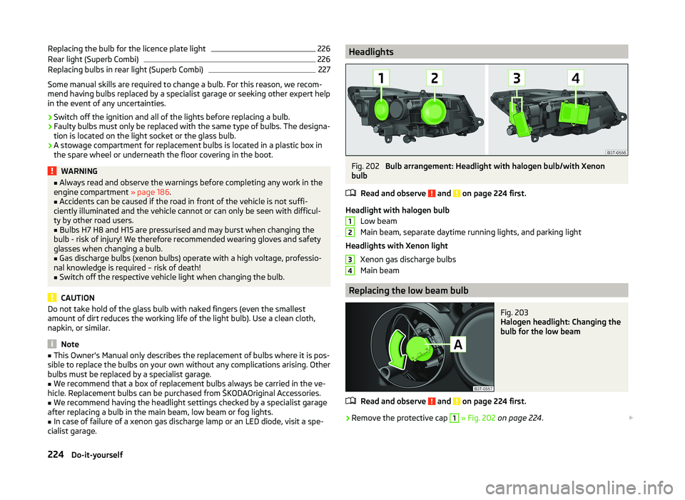
HeadlightsFig. 202
Bulb arrangement: Headlight with halogen bulb/with Xenon
bulb
Read and observe
and on page 224 first.
Headlight with halogen bulb Low beam
Main beam, separate daytime running lights, and parking light
Headlights with Xenon light Xenon gas discharge bulbs
Main beam
Replacing the low beam bulb
Fig. 203
Halogen headlight: Changing the
bulb for the low beam
Read and observe and on page 224 first.
›
Remove the protective cap
1
» Fig. 202 on page 224 .
1234224Do-it-yourself