display SKODA SUPERB 2012 2.G / (B6/3T) Owner's Guide
[x] Cancel search | Manufacturer: SKODA, Model Year: 2012, Model line: SUPERB, Model: SKODA SUPERB 2012 2.G / (B6/3T)Pages: 235, PDF Size: 5.86 MB
Page 30 of 235

For the sake of the environment
Dispose of the used battery in accordance with national legal provisions. Note
■ Please approach a ŠKODA Service Partner if you lose a key as they can obtain a
new one for you. ■ The system has to be synchronised, if the vehicle cannot be unlocked or locked
with the remote control key after replacing the battery » page 32. ÐChild safety lock
Fig. 10
Child safety locks on the rear
doors
The child safety lock prevents the rear door from being opened from the inside.
The door can only be opened from the outside.
You can switch the child safety lock on and off using the vehicle key.
Switching on
› Use the vehicle key to turn the slit in the rear door in the direction of the ar-
row » Fig. 10.
Switching off
› Use the vehicle key to turn the slit to the right in the opposite direction to the
arrow. Ð Central locking system
Introductory information
When using the central locking and unlocking system, all the doors and the fuel
filler flap are locked or unlocked at the same time (if it was not set differently in
the menu item Settings - Convenience
of the information display). The boot lid is
unlocked when opening. The boot lid can then be opened by pressing the handle
on the lower edge of the boot lid » page 36.
Indicator light in the driver's door
After locking the vehicle, the indicator light flashes for around 2 seconds in quick
succession, afterwards it begins to flash evenly at longer intervals.
If the vehicle is locked and the safe securing system » page 29 is not operating,
the indicator light in the driver door flashes for about 2 seconds fast, goes out
and starts to flash evenly at longer intervals after about 30 seconds.
If the indicator light first of all flashes fast for about 2 seconds, afterwards lights
up for about 30 seconds without interruption and then flashes slowly, there is a
fault in the system of the central locking or in the interior monitor and in the tow-
ing protection monitoring » page 34. Seek help from a ŠKODA specialist garage.
Convenience operation of windows
The windows can be opened and closed when unlocking and locking the vehi-
cle » page 42. Ð Individual settings
Opening a single door
This selection function makes it possible to only unlock the driver's door. The oth-
er doors and the fuel filler flap remain locked and are only unlocked after being
opened again.
Unlocking a vehicle side door
This selection function enables to unlock both doors on the driver's side. The oth-
er doors and the fuel filler flap remain locked and are only unlocked after being
opened again.
Unlocking the vehicle with the KESSY system
This selection function enables to unlock all the doors, individual doors, both
doors on the left and right vehicle side or to unlock the driver and front passenger
door at the same time. The other doors and the fuel filler flap remain locked and £
28 Using the system
Page 31 of 235
are only unlocked after being unlocked again using the unlock button on the re-
mote control key
» Fig. 8 on page 27
or the central locking button » Fig. 11 on
page 30.
Automatic locking and unlocking
All the doors and the boot lid are locked automatically once the car reaches a
speed of about 15 km/h.
If the ignition key is withdrawn, the car is then automatically unlocked again. In
addition, it is possible for the driver or front passenger to unlock the car by press-
ing the central locking button » page 30.
The vehicle doors can also be unlocked and opened by pulling once on the door
opening lever. WARNING
Locked doors prevent unwanted entry into the vehicle from outside, for exam-
ple at road crossings. Locked doors do, however, make it more difficult for res-
cuers to get into the vehicle in an emergency - danger to life! Note
■ You can have the individual settings activated by a ŠKODA
Service Partner or
you can activate them yourself with the help of the information display » page 16,
Settings. ■ In the event of an accident in which the airbags are deployed, the locked doors
are automatically unlocked in order to enable rescuers to gain access to the vehi-
cle. ■ Only the driver's door can be unlocked or locked using the key if the central
locking system fails » page 35. The other doors and the boot lid can be manually
locked or unlocked. ■ Emergency locking of the door »
page 35.
■ Emergency unlocking of the boot lid » page 37. ÐSafe securing system
The central locking system is equipped with a safe securing system. The door
locks are blocked automatically if the vehicle is locked from the outside. The indi-
cator light flashes for around 2 seconds in quick succession, afterwards it begins
to flash evenly at longer intervals. It is not possible to open the doors with the
door handle either from the inside or from the outside. This acts as an effective
deterrent for attempts to break into your vehicle. The safe securing system can be deactivated within 2 seconds by double locking
the vehicle.
If the safe securing system is not in operation:
› the indicator light in the driver door flashes rapidly for about 2
seconds, goes
out and starts to flash at regular, longer intervals after about 30 seconds;
› is the filler flap locked.
The safe securing system is activated again the next time the vehicle is unlocked
and locked.
If the vehicle is locked and the safe securing system is deactivated, the vehicle
can be opened from the inside by pulling the door opening lever. WARNING
If the vehicle is locked from the outside and the safe securing system is acti-
vated, there must not be any person in the vehicle as it is then no longer pos-
sible to open either a door or a window from the inside. The locked doors
make it more difficult for rescuers to get into the vehicle in an emergency -
hazard! Note
■ The anti-theft alarm system is activated when the vehicle is locked even if the
safe securing system is deactivated. The interior monitor is however not activa-
ted. ■ After locking the vehicle, you will be informed that the safe securing system is
activated by means of the message CHECK DEADLOCK on the instrument cluster
display. On vehicles that are equipped with an information display, the following
message will appear Check deadlock! Owner's manual! appears.Ð
29
Unlocking and locking
Page 35 of 235
Note
■ If the battery in the remote control key is weak or discharged, the vehicle may
not be unlocked or locked via the KESSY system. In this case, use the emergency
unlocking or emergency locking of the driver's door » page 35.
■ The KESSY system can find the valid key, even if it was left in the front area of
the vehicle's roof for example. Make sure you know where the valid remote con-
trol key is at all times. ■ When locking/unlocking the vehicle using the sensors 1
» Fig. 13 or 2
do not
use gloves or other objects that might prevent the hand from coming into direct
contact with the sensor.
■ If you unlock the vehicle by means of the sensor in the handle and do not open
a door or the boot lid within the next 30
seconds, the vehicle will lock again auto-
matically and the safe securing system or anti-theft alarm system will be reactiva-
ted. This function is intended to prevent the car being unlocked unintentionally. ÐProtection against inadvertently locking the key in the vehicle
If the key, which was used to lock the vehicle, remains in the vehicle in the area D
» Fig. 13 on page 32
after locking and closing all of the doors including the boot
lid, the protection against inadvertently locking the key in the vehicle is activated
and the vehicle unlocks itself again.
The following message is displayed in the information display or display of the in-
strument cluster: Key in vehicle. or KEY IN VEHICLE.
Additionally, on vehicles which are fitted with the anti-theft alarm system, an au-
dible signal sounds. ÐMessages in the instrument cluster display
■ Key not found. or No Key
This message is displayed when you wish to start the engine and the system can-
not detect a valid key in the vehicle. This can occur if the key is outside the vehi-
cle, the battery in the key is discharged, the key is defective or the electromag-
netic field is strongly disturbed. This message is also displayed when the ignition
is switched on or the engine is running and the system cannot detect a valid key
in the vehicle.
■ Keyless faulty. or CHECK KEYLESS.
Error in the KESSY system; seek help from a
ŠKODA specialist garage. ■
Renew key battery! or KEY BATTERY
Low voltage of the remote control key battery, change the battery. Ð Parking the vehicle
If the vehicle is not unlocked within 60 or 90 hours, the sensors 1
» Fig. 13
on
page 32 and 2
in the handle of the front passenger's door are automatically de-
activated.
Activation after 60 hours
› Unlock the driver's door using the sensor 2
» Fig. 13 on page 32
.
› Press the handle of the boot lid.
› Unlock the vehicle using the button on the remote control key,
› Unlocking the driver's door in an emergency
» page 35.
Activation after 90 hours
› Unlock the vehicle using the button on the remote control key,
› Unlocking the driver's door in an emergency
» page 35.Ð Anti-theft alarm system
Introductory information
The anti-theft alarm system increases the level of protection against people
seeking to break into the vehicle. The system triggers audible and visual warning
signals if an attempt is made to break into the vehicle.
How is the alarm system activated?
The anti-theft alarm system is activated when the vehicle is locked with the radio
remote control or the key in the driver's door . The door contact monitoring is ac-
tivated approx. 15 seconds after the locking. The interior and the towing protec-
tion monitoring are activated approx. 30 seconds after the locking. If a door is
opened during activation, the monitoring is only activated 5 seconds after closing.
How is the alarm system deactivated?
The alarm system is deactivated by pressing the unlock button on the radio re-
mote control. The anti-theft alarm system is reactivated if the vehicle is not
opened within 30 seconds after transmitting the radio signal.
The alarm system is also deactivated if you unlock the driver door using the key
within 45 seconds of locking the vehicle. £
33
Unlocking and locking
Page 51 of 235

Switching lights on and off
Fig. 30
Dash panel: Light switch
First read and observe the introductory information and safety warn-
ings on page 48.
Switching on the parking light
›
Turn the light switch
» Fig. 30 to position .
Switching on the low beam and main beam
› Turn the light switch to position
.
› Push the main beam lever slightly forward in the spring-tensioned position to
switch on the main beam » Fig. 36 on page 54.
Switching off lights (except daylight driving lights)
› Turn the light switch to position 0. ÐDAY LIGHT function (Daylight driving light)
First read and observe the introductory information and safety warn-
ings on page 48.
Switching on daylight driving lights
›
Turn the ignition on and turn the light switch to position 0 or
.
Deactivating the function daylight driving lights
› Pull the turn signal light lever towards the steering wheel within 3
seconds of
switching on the ignition and at the same time, slide it downwards and hold it in
this position for at least 3
seconds.
ä
ä Activating the function daylight driving lights
› Pull the turn signal light lever towards the steering wheel within 3
seconds of
switching on the ignition and at the same time, slide it upwards and hold it in
this position for at least 3
seconds.
On vehicles with an information display, the daylight driving lights can also be ac-
tivated or deactivated via the menu:
■ Settings
■ Lights & Vision
On vehicles with separate lights for daylight driving lights in the fog lights, the
parking lights and the licence plate light do not come on when activating the
function daylight driving lights (neither front nor rear).
When the daylight driving lights are switched on, the lighting of the instrument
cluster is switched on as well. Ð Automatic driving lamp control
Fig. 31
Dash panel: Light switch
First read and observe the introductory information and safety warn-
ings on page 48.
Switching on
›
Turn the light switch
» Fig. 31 to position .
Switching off
› Turn the light switch to the position 0,
or .
If the light switch is in the position , the symbol illuminates when the ignition
is switched on next to the light switch. If the low beam is activated with the
light sensor, the symbol illuminates additionally next to the light switch. £
ä
49
Lights and visibility
Page 53 of 235
Note
■ If the COMING HOME/LEAVING HOME function is switched on constantly, the
battery will be heavily discharged particularly over short distances. ■ The illumination period for the COMING HOME/LEAVING HOME function can be
changed by means of the information display. ÐAdaptive headlights (AHL)
First read and observe the introductory information and safety warn-
ings on page 48.
Switching on
›
Turn the light switch
» Fig. 31 on page 49 to position
.
The AHL system is activated if:
› the light sensor recognises a low light intensity,
› no reverse gear is engaged,
› the operation mode “tourist light” is not switched on.
The light sensor switches on the full outer illumination at low light intensity.
The AHL system makes it possible to change the length and width of illumination
from the headlights. The length and width of illumination changes automatically
in relation to the vehicle speed and the use of the windscreen wiper.
The AHL system operates in the following modes.
Out of town mode
The “out of town” mode is a basic mode. The dispersion of the cone of light in
front of the vehicle is similar to the low beam. The mode is active if none of the
following modes are active.
Rain mode
In the “rain” mode the dispersion of the cone of light in front of the vehicle is wid-
er and the width of illumination is shorter, so that during bad weather (rain) the
dazzling of the oncoming drivers can be reduced. The mode is activated at speeds
of 15 – 70 km/h and if the windscreen wipers continuously operate for a period of
time longer than 2 minutes. The mode is deactivated when dropping below or ex-
ceeding the set speed limit or if the windscreen wipers have been switched off
for a period of time longer than 8 minutes. ä
City mode
In the
“city” mode, the dispersion of the cone of light in front of the vehicle is wid-
er and the width of illumination is shorter. The aim is to illuminate also the adja-
cent footpaths, crossings, pedestrian crossings, etc. The mode is active at speeds
of 15-50 km/h.
Motorway mode
In the “motorway” mode, the dispersion of the cone of light is adapted so that it
also illuminates the left (or right) 1)
lane of the motorway, so that the driver can re-
act in time to an obstacle or any other danger. The mode is activated gradually
from a speed of 90 km/h. It is most effective at speeds above 120 km/h.
Tourist light
This mode makes it possible to drive in countries with opposing traffic system,
driving on the left/right, without dazzling the oncoming vehicles. When the “tou-
rist light” mode is active, the above-mentioned modes and the side swivel of the
headlights is deactivated.
The “tourist light” mode is activated/deactivated via the information display in
the menu:
■ Settings
■ Travel mode
■ Off
■ Switched on
Cornering lights
The cornering lights are used to illuminate the curves by means of the cone of
light swivelling together with the front headlight with Xenon lights. This function
is active when the speed of the car increases to more than 10 km/h. WARNING
If the cornering lights are defective, the headlights are automatically lowered
to the emergency position, which prevents a possible dazzling of oncoming
traffic. Thus the illuminated length of the road is shortened. Drive carefully
and visit a ŠKODA specialist garage as soon as possible. Note
The AHL system complements the functions of the fog lights with the function
CORNER » page 52 and the function of the dynamic headlight beam adjustment. Ð1)
It is valid for vehicles which are designed for driving on the left.
51
Lights and visibility
Page 55 of 235
Instrument lighting
Fig. 33
Dash panel: Instrument lighting
First read and observe the introductory information and safety warn-
ings on page 48.
›
Switch on the light.
› Turn the control dial
» Fig. 33 to the desired intensity of the instrument light-
ing.
The illumination intensity of the Information display »
page 15 is set automatical-
ly. It is only possible to adjust the instrument lighting with the control dial if the
light intensity drops below the set value of the light sensor. ÐHeadlight beam adjustment
Fig. 34
Dash panel: Lights and visibility
First read and observe the introductory information and safety warn-
ings on page 48.
›
Switch on the light.
› Turn the control dial
» Fig. 34 to the desired width of illumination.
ä
ä Settings
The positions correspond approximately to the following car load.
Front seats occupied, boot empty.
All seats occupied, boot empty.
All seats occupied, boot loaded.
Driver seat occupied, boot loaded. CAUTION
Always adjust the headlight range adjustment in such a way that:
■ it does not dazzle other road users, especially oncoming traffic;
■ and the range is sufficient for safe driving. Note
The Bi-Xenon bulbs adapt automatically to the load and driving state of the vehi-
cle (e.g. speed, accelerating, braking) when the ignition is switched on and when
driving. Vehicles that are equipped with Bi-Xenon headlights do not have a man-
ual headlight range adjustment control. Ð Switches for the hazard warning light system
Fig. 35
Dash panel: Switch for hazard
warning lights
First read and observe the introductory information and safety warn-
ings on page 48.
›
Press switch
» Fig. 35 to switch the hazard warning light system on or off. £ -
1
2
3
ä
53
Lights and visibility
Page 56 of 235
All the turn signal lights on the vehicle flash at the same time when the hazard
warning light system is switched on. The indicator light for the turn signals and
the indicator light in the switch also flash at the same time. The hazard warning
light system can also be operated if the ignition is switched off.
The hazard warning light system is switched on automatically if an airbag is de-
ployed in the event of an accident.
Note
The hazard warning light system must be switched on if, for example:
■ you encounter a traffic congestion;
■ your vehicle breaks down or an emergency situation occurs. ÐTurn signal and main beam lever
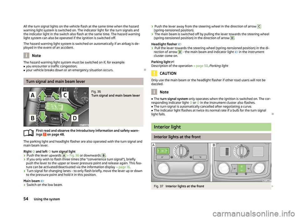
Fig. 36
Turn signal and main beam lever
First read and observe the introductory information and safety warn-
ings on page 48.
The parking light and headlight flasher are also operated with the turn signal and
main beam lever.
Right and left turn signal light
› Push the lever upwards A
» Fig. 36
or downwards B
.
› If you only wish to flash three times (the "convenience turn signal"), briefly
push the lever to the upper or lower pressure point and release again. This fea-
ture can be activated/deactivated via the information display » page 16.
› Turn signal for changing lanes - to only flash briefly, move the lever up or down
to the pressure point and hold it in this position.
Main beam
› Switch on the low beam.
ä ›
Push the lever away from the steering wheel in the direction of arrow C
(spring-tensioned position).
› The main beam is switched off by pulling the lever towards the steering wheel
(spring-tensioned position) in the direction of arrow D
.
Headlight flasher
› Pull the lever towards the steering wheel (spring-tensioned position) in the di-
rection of arrow D
- the main beam and indicator light
in the instrument
cluster come on.
Parking light
Description of the operation » page 50, Parking light CAUTION
Only use the main beam or the headlight flasher if other road users will not be
dazzled. Note
■ The turn signal system only operates when the ignition is switched on. The cor-
responding indicator light or
in the instrument cluster also flashes.
■ The turn signal is automatically cancelled after negotiating a curve.
■ The indicator light flashes at twice its normal rate if a bulb for the turn signal
light fails. Ð Interior light
Interior lights at the front
Fig. 37
Interior lights at the front £
54 Using the system
Page 63 of 235

›
Set the desired break between the individual wiper strokes with the switch A
.
Slow wipe
› Position the lever upwards into position 2
» Fig. 47.
Fast wipe
› Position the lever upwards into position 3
» Fig. 47.
Automatic wipe/wash for windscreen
› Pull the lever towards the steering wheel into the spring-tensioned position 5
» Fig. 47, the washer system is activated immediately, while the windscreen
wipers start wiping a little later. The wash system and the windscreen wiper op-
erate simultaneously at a speed of more than 120
km/h.
› Release the lever. The windscreen wash system stops and the wiper continues
for another 3 - 4 wiper strokes (depending on the period of spraying of the
windscreen). At a speed of more than 2 km/h, the wiper wipes once again 5 sec-
onds after the last wiper stroke in order to wipe the last drops from the wind-
screen. This feature can be activated/deactivated by a
ŠKODA specialist garage.
Rain sensor
› Place the lever in position 1
» Fig. 47.
› The sensitivity of the sensor can be set individually with the switch A
.
Wiping the rear window pane (Combi)
› Push the lever away from the steering wheel into position 6
» Fig. 47
and the
windscreen wiper will operate every 6
seconds.
Automatic wipe/wash for the rear window (Combi)
› Press the lever completely away from the steering wheel into the spring-ten-
sioned position 7
» Fig. 47, the washer system is activated immediately, while
the windscreen wiper starts wiping a little later. The wiper and washer system
will operate as long as the lever is held in this position.
› Release the lever. The washer system stops and the wiper continues for anoth-
er 2 to 3
wiper strokes (depending on the duration of the spraying process). The
lever will stay in position after releasing it 6
.
Switching windscreen wipers off
› Move the lever back into the home position 0
» Fig. 47.
Winter position
If the windscreen wipers are in rest position, they cannot be folded out from the
windscreen. For this reason we recommend adjusting the windscreen wipers in
winter so that they can be folded out from the windscreen easily. This rest position is set as follows:
›
Switch on the windscreen wipers.
› Switch off the ignition. The windscreen wipers remain in the position in which
they were when switching off the ignition.
The service position can also be used as a winter position » page 62.Ð Automatic rear window wiper (Combi)
First read and observe the introductory information and safety warn-
ings on page 59.
If the windscreen wiper is in position 2
» Fig. 47 on page 60 or 3
the rear win-
dow is wiped every 30 or 10 seconds if the vehicle's speed exceeds 5
km/h.
When the rain sensor is active (the lever is in the position 1
) the function is only
active if the windscreen wipers operate in continuous mode (no break between
each wiping process).
Activation/deactivation
The function of the automatic rear window wiper is activated/deactivated in the
information display in the menu:
■ Settings
■ Lights & Vision
■ Rear wiper Ð Alternative park position of the rear window wiper (Combi)
First read and observe the introductory information and safety warn-
ings on page 59.
Each time after switching off the engine for the second time, the wiper blade of
the rear window wiper is tilted. This prolongs the life of the wiper blade.
Activation/deactivation
› Switch on the ignition.
› Push the operating level into the position 6
» Fig. 47 on page 60 five times in
succession within 5
seconds.
› Switch off the ignition. After switching on the ignition again, the alternative
park position of the rear window wiper is activated/deactivated. Ð
ä
ä
61
Lights and visibility
Page 65 of 235

Attaching the wiper blade
›
Push the windscreen wiper blade until the stop and it locks in place.
› Check that the wiper blade is correctly attached.
› Fold the wiper arm back to the windscreen. ÐRear window
Manual dimming interior mirror
Basic setting
› Pull the lever on the bottom edge of the mirror forward.
Dimming mirror
› Push the lever on the bottom edge of the mirror backwards. ÐAutomatic dimming interior mirror
Fig. 50
Automatic dimming interior mir-
ror
Switching on automatic dimming › Press the button B
» Fig. 50, the indicator light A
lights up.
Switching off automatic dimming
› Press the button B
again, the indicator light A
goes out.
If the automatic dimming is switched on, the mirror dims automatically depend-
ing on the light striking the mirror from the rear. The mirror has no lever on the
bottom edge of the mirror. After the reverse gear is engaged, the mirror always
moves back into the normal position.
Do not attach external navigation devices on to the windscreen or in the vicinity
of the automatic dimming interior mirror » . WARNING
The display lighting on the external navigation device may cause the automat-
ic dimming interior mirror to malfunction – risk of accident. Note
■ Automatic mirror dimming operates only properly if the sun screen for the rear
window in the housing on the boot cover is not in use or the light striking the in-
terior rear-view mirror is not affected by other objects. ■ Do not affix any stickers in front of the light sensor, so that they do not impair
the automatic dimming function or put it out of operation. ■ If the automatic interior mirror dimming is switched off, the exterior mirror dim-
ming is also switched off. Ð Additional rear-view mirror
Fig. 51
Additional interior mirror
The additional interior mirror allows the driver a wider field of view of the rear
seats.
Adjusting the angle › Adjust the mirror in direction of arrow to the desired position. WARNING
Concentrate at all times fully on your driving! As the driver you are fully re-
sponsible for the operation of your vehicle. Use the additional interior mirror
only to such an extent that you are in full control of your vehicle at any time. Ð
63
Lights and visibility
Page 66 of 235
Exterior mirror
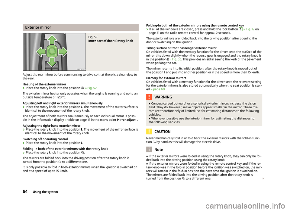
Fig. 52
Inner part of door: Rotary knob
Adjust the rear mirror before commencing to drive so that there is a clear view to
the rear.
Heating of the external mirror
› Place the rotary knob into the position
» Fig. 52.
The exterior mirror heater only operates when the engine is running and up to an
outside temperature of +20 °C.
Adjusting left and right exterior mirrors simultaneously
› Place the rotary knob into the position
. The movement of the mirror surface is
identical to the movement of the rotary knob.
The adjustment of both mirrors simultaneously or each individual mirror is possi-
ble in the Information display » table on page 17
in the menu point Mirror adjust. .
Adjusting the right-hand exterior mirror
› Place the rotary knob into the position
. The movement of the mirror surface is
identical to the movement of the rotary knob.
Switching off operating control
› Place the rotary knob into the position
.
Folding-in both of the exterior mirrors with the rotary knob
› Place the rotary knob into the position
.
The mirrors are folded back into the driving position after the rotary knob is
turned from the position to a different one.
It is only possible to fold in both exterior mirrors when the ignition is switched on
and at a speed of up to 15
km/h. Folding-in both of the exterior mirrors using the remote control key
› If all of the windows are closed, press and hold the lock button 3
» Fig. 12 on
page 31 on the radio remote control for approx. 2
seconds.
The exterior mirrors are folded back into the driving position after opening the
door or switching on the ignition.
Tilting surface of front passenger exterior mirror
On vehicles fitted with the memory function for the driver seat, the surface of the
mirror tilts down slightly when the reverse gear is engaged and the rotary knob is
in the position » Fig. 52. This provides an aid in seeing the kerb of the pavement
when parking the car.
The mirror returns into its initial position, after the rotary knob is moved out of
the position and put into another position or if the speed is more than 15 km/h.
Memory for exterior mirrors
On vehicles fitted with a memory function for the driver seat, the relevant setting
for the exterior mirrors is also stored automatically when the seat position is stor-
ed » page 68. WARNING
■ Convex (curved outward) or a spherical exterior mirrors increase the vision
field. They do, however, make objects appear smaller in the mirror. These mir-
rors are therefore only of limited use for estimating distances to the following
vehicles.
■ Whenever possible use the interior mirror for estimating the distances to
the following vehicles. CAUTION
Never mechanically fold in or fold back the exterior mirrors with the fold-in func-
tion by hand as this will damage the electric drive. Note
■ If the exterior mirrors were folded in using the rotary knob, they can only be fol-
ded back into the driving position using the rotary knob. ■ If the exterior mirrors were folded in using the remote control key and if the ro-
tary knob was in the fold-in position before the ignition was switched on, the mir-
rors will remain in the fold-in position the next time the ignition is switched on.
The mirrors are folded back into the driving position after the rotary knob is
turned from the position to a different one. £
64 Using the system