brake sensor SKODA SUPERB 2012 2.G / (B6/3T) Owner's Manual
[x] Cancel search | Manufacturer: SKODA, Model Year: 2012, Model line: SUPERB, Model: SKODA SUPERB 2012 2.G / (B6/3T)Pages: 235, PDF Size: 5.86 MB
Page 20 of 235

Door, boot lid and bonnet warning
First read and observe the introductory information and safety warn-
ings on page 15.
If at least one door is open, or the boot or bonnet is open, the information display
indicates the relevant
open door or boot/bonnet.
An audible signal also sounds if the vehicle is travelling at more than 6
km/h.ÐAuto Check Control
First read and observe the introductory information and safety warn-
ings on page 15.
Vehicle condition
Certain functions and conditions of individual vehicle systems are checked contin-
uously when the ignition is switched on and also while driving.
Some error messages and other information are displayed in the information dis-
play. The messages are displayed at the same time as the symbols in the informa-
tion display or the indicator lights in the instrument cluster » page 18.
If there is at least one error message, the menu item Vehicle status is displayed
in the menu. After selecting this menu the first of the error messages is dis-
played. Several error messages are shown on the display under the message e.g.
1/3. This indicates that the first of a total of three error messages is being dis-
played.
Warning symbols
Engine oil pressure too low
» page 21
Clutches of the automatic gearbox are too
hot » page 18
Check engine oil level,
engine oil sensor faulty
» page 22
Thickness of brake pads
» page 25
Problem with engine oil pressure
» page 18ä
ä
Clutches of the automatic gearbox are too hot
A symbol in the information display indicates that the temperature of the
clutches of the automatic gearbox is too high.
The following is displayed in the information display: Gearbox overheated. Stop! Owner's man.!
Stop the vehicle, switch off the engine, and wait until the symbol disappears -
risk of gearbox damage! You can continue your journey as soon as the symbol dis-
appears.
Problem with the engine oil pressure
If the symbol is shown in the information display, you must have your vehicle
checked immediately by a
ŠKODA specialist garage. The information about the
maximum permissible engine speed is displayed together with this symbol. WARNING
If you have to stop for technical reasons, then park the vehicle at a safe dis-
tance from the traffic, switch off the engine and activate the hazard warning
light system » page 53. Note
■ If warning messages are shown in the information display, these messages
must be confirmed with the button B
» Fig. 7 on page 16 on the windscreen wip-
er lever or with the button D
on the multifunction steering wheel to call up the
main menu. ■ As long as the operational faults are not rectified, the symbols are always indi-
cated again. After they are displayed for the first time, the symbols continue to be
indicated without any extra messages for the driver. Ð Indicator lights
Overview
The indicator lights show certain functions/faults and may be accompanied by au-
dible signals.
When switching on the ignition, some indicator lights illuminate briefly as a func-
tion test. These indicator lights will disappear several seconds after the vehicle is
started. £
18 Using the system
Page 169 of 235

General Maintenance
Taking care of and cleaning the vehicle
Taking care of your vehicle
ä
Introduction
This chapter contains information on the following subjects:
Washing the vehicle 168
Automatic car wash systems 168
Washing by hand 168
Washing with a high-pressure cleaner 168
Preserving and polishing the vehicle paintwork 169
Chrome parts 169
Paint damage 169
Plastic parts 169
De-icing windows and exterior mirrors 170
Radio reception and aerial 170
Headlight lenses 170
Rubber seals 170
Door lock cylinders 170
Wheels 171
Underbody protection 171
Protection of hollow spaces 171
Artificial leather and materials 172
Fabric covers on electrically heated seats 172
Natural leather 172
Seat belts 173
Regular and proper care help to retain the efficiency and value of your vehicle. It
may also be one of the requirements for the acceptance of warranty claims relat-
ing to corrosion damage and paint defects on the bodywork.
We recommend using care products from
ŠKODA Original Accessories that are
available from ŠKODA Service Partners. The instructions for use on the package
must be observed. WARNING
■ Care products may be harmful to your health if not used according to the in-
structions.
■ Always store care products in a safe place, out of the reach of children - risk
of poisoning! ■ When washing your vehicle in the winter: Water and ice in the brake system
can affect the braking efficiency - risk of accident! ■ Only wash the vehicle when the ignition is switched off - risk of accident!
■ Protect your hands and arms from sharp-edged metal parts when cleaning
the underfloor, the inside of the wheel housings or the wheel trims - risk of
cuts!
■ Air fresheners and scents can be hazardous to heath when the temperature
inside the vehicle is high. CAUTION
■ Be sure to check clothing for colourfastness to avoid any damage or visible
stains on the material (leather), panels and textiles.
■ Cleaners containing solvents can damage the material being cleaned.
■ Do not wash your vehicle in bright sunlight - risk of paint damage.
■ If washing the vehicle in the winter using a hose or high-pressure cleaner, en-
sure that the jet of water is not aimed directly at the locking cylinders or the
door/panel joints - risk of freezing!
■ Do not use any insect sponges, rough kitchen sponges or similar cleaning prod-
ucts - risk of damaging the surface of paintwork.
■ Do not stick any stickers on the inside of the rear windows, the rear side win-
dows and in the vicinity of the heating elements on the windscreen or near the
window aerial. These may get damaged. With regard to the antenna, they may in-
terfere with the radio or navigation system.
■ Do not clean the inside of the windows with sharp-edged objects or corrosive
and acidic cleaning agents - risk of damaging the heating elements or window
aerial.
■ Do not attach scents and air fresheners to the dashboard - risk of damage to
the dashboard.
■ To avoid damaging the parking aid sensors while cleaning with high-pressure
cleaners or steam jets, the sensors must only be directly sprayed for short periods
while a minimum distance of 10
cm must be observed.
■ Do not clean the roof trim with a brush - risk of damage to the trim surface. £
167
Taking care of and cleaning the vehicle
Page 194 of 235

Tyre control display
Fig. 169
Button for setting the tyre infla-
tion pressure control value
First read and observe the introductory information and safety warn-
ings on page 187.
The tyre control display compares the speed and thus the rolling circumference of
the individual wheels with the help of the ABS sensors. If the rolling circumfer-
ence of a wheel is changed, the indicator light
in the instrument clus-
ter » page 25, Tyre control display and an audible signal sounds.
The rolling circumference of the tyre can change if: › the tyre inflation pressure is too low;
› the structure of the tyre is damaged;
› the vehicle is loaded on one side;
› the wheels of an axle are loaded heavily (e.g. when towing a trailer or when
driving uphill or downhill);
› snow chains are mounted;
› the temporary spare wheel is mounted;
› one wheel per axle was changed.
Basic setting of the system
After changing the tyre inflation pressure, after changing one or several wheels,
the position of a wheel on the vehicle (e.g. exchanging the wheels between the
axles) or when the indicator light lights up while driving, a basic setting of the
system must be carried out as follows: › Inflate all of the tyres to the specified inflation pressure
» page 188, Service life
of tyres.
› Switch on the ignition.
ä
›
Press and hold the button
» Fig. 169
for longer than 2 seconds. While
pressing the button, the indicator light illuminates. At the same time the sys-
tem memory is erased and the new calibration is started, which is confirmed
with an audible signal and then the indicator light goes out.
› If the indicator light
does not go out after the basic setting, this indicates a
system fault. Seek help from a ŠKODA specialist garage.
The indicator light is lit
If the tyre inflation pressure of at least one wheel is insufficiently inflated in com-
parison to the stored basic value, the indicator light » lights up.
The indicator light flashes
If the indicator light flashes, there is a system fault. Seek help from a
ŠKODA spe-
cialist garage to correct the fault. WARNING
■ When the indicator light illuminates, immediately reduce the speed and
avoid sudden steering and brake manoeuvres. Stop the vehicle as soon as
possible and inspect the tyres and their inflation pressure.
■ Under certain circumstances (e.g. sporty style of driving, wintry or unpaved
roads) the indicator light can be delayed or does not light up at all.
■ The tyre control display does not absolve the driver of the responsibility to
ensure the correct tyre inflation pressure. For this reason, the tyre inflation
pressure must be checked regularly. Note
■ The tyre control display does therefore not replace the regular tyre inflation
pressure control, as the system cannot detect an even loss of pressure. ■ The tyre control display cannot provide a warning in the event of very rapid tyre
inflation pressure loss, e.g. in the case of sudden tyre damage. In this case care-
fully bring the vehicle to a standstill without sudden steering movements or
sharp braking.
■ To ensure a proper functioning of the tyre control display, it is necessary to re-
peat the basic setting every 10 000 km or once a year. Ð
192 General Maintenance
Page 210 of 235

Fuses in the dash panel
Fig. 183
Fuse box cover/Schematic diagram of the fuse box
First read and observe the introductory information and safety warn-
ings on page 207.
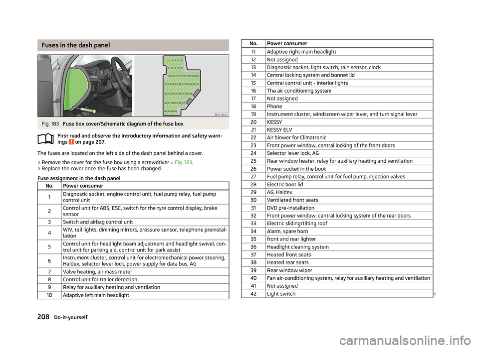
The fuses are located on the left side of the dash panel behind a cover.
›
Remove the cover for the fuse box using a screwdriver
» Fig. 183.
› Replace the cover once the fuse has been changed.
Fuse assignment in the dash panel No. Power consumer
1 Diagnostic socket, engine control unit, fuel pump relay, fuel pump
control unit
2 Control unit for ABS, ESC, switch for the tyre control display, brake
sensor
3 Switch and airbag control unit
4 WIV, tail lights, dimming mirrors, pressure sensor, telephone preinstal-
lation
5 Control unit for headlight beam adjustment and headlight swivel, con-
trol unit for parking aid, control unit for park assist
6 Instrument cluster, control unit for electromechanical power steering,
Haldex, selector lever lock, power supply for data bus, AG
7 Valve heating, air mass meter
8 Control unit for trailer detection 9 Relay for auxiliary heating and ventilation
10 Adaptive left main headlight ä
No. Power consumer
11 Adaptive right main headlight
12 Not assigned
13 Diagnostic socket, light switch, rain sensor, clock
14 Central locking system and bonnet lid 15 Central control unit - interior lights
16 The air conditioning system 17 Not assigned
18 Phone 19 Instrument cluster, windscreen wiper lever, and turn signal lever
20 KESSY 21 KESSY ELV
22 Air blower for Climatronic
23 Front power window, central locking of the front doors
24 Selector lever lock, AG 25 Rear window heater, relay for auxiliary heating and ventilation
26 Power socket in the boot 27 Fuel pump relay, control unit for fuel pump, injection valves
28 Electric boot lid 29 AG, Haldex
30 Ventilated front seats 31 DVD pre-installation
32 Front power window, central locking system of the rear doors
33 Electric sliding/tilting roof
34 Alarm, spare horn 35 front and rear lighter
36 Headlight cleaning system 37 Heated front seats
38 Heated rear seats 39 Rear window wiper
40 Fan air-conditioning system, relay for auxiliary heating and ventilation 41 Not assigned
42 Light switch £208
Do-it-yourself
Page 211 of 235

No. Power consumer
43 Control unit for trailer detection
44 Control unit for trailer detection 45 Control unit for trailer detection
46 Switch for seat heating 47 Telephone preinstallation
48 Preparation for the aftermarket radio 49 Not assigned Ð
Fuses in the engine compartment
Fig. 184
Schematic diagram of the fuse box - version A/version B Fig. 185
Cover for the fuse box in the en-
gine compartment
First read and observe the introductory information and safety warn-
ings on page 207.
ä On some vehicles, the battery cover must be removed before removing the cover
for the fuse box
» page 184.
› The cover for the fuse box is removed by pushing the circlips A
» Fig. 185
up-
wards as far as the stop. The symbol is displayed behind the clip. Now remove
the cover.
› Once the fuse has been removed, place the cover on the fuse box and push the
circlips A
back as far as the stop. The symbol is displayed behind the clip. The
cover is locked into position.
Fuse assignment in the engine compartment - version A No. Power consumer
F1 Front right main headlight, right tail light
F2 Valves for ABS
F3-4 Not assigned F5 Horn
F6-12 Not assigned F13 Control unit for automatic gearbox
F14 Not assigned F15 Coolant pump
F16 Not assigned F17 Instrument cluster, windscreen wiper lever, and turn signal lever
F18 Audio amplifier (sound system) F19 Radio
F20-22 Not assigned F23 Engine control unit
F24 Data bus control unit
F25-26 Not assigned F27 Fuel dosage valve
F28 Engine control unit F29 Main relay
F30 Auxiliary heating and ventilation control unit F31 Windscreen wipers
F32-37 Not assigned F38 Radiator fan, valvesF39 Clutch/brake pad sensor £ 209
Fuses and light bulbs