low beam SKODA SUPERB 2013 2.G / (B6/3T) User Guide
[x] Cancel search | Manufacturer: SKODA, Model Year: 2013, Model line: SUPERB, Model: SKODA SUPERB 2013 2.G / (B6/3T)Pages: 274, PDF Size: 17.31 MB
Page 151 of 274

Driving through water on streetsFig. 129
Driving through water
First read and observe the introductory information given on page 147.
The following instructions must be observed if vehicle damage is to be avoided
when driving through water (e.g. flooded roads).
›
Determine the depth of the water before driving through.
The water level must not reach above the bar on the lower beam » Fig. 129.
›
Do not drive any faster than at a walking speed.
At a higher speed, a water wave can form in front of the vehicle, which can cause
water to penetrate into the engine's air induction system or other parts of the ve-
hicle.
›
Never stop in the water, do not reverse and do not switch the engine off.
›
Deactivate the START-STOP system before driving through water » page 159,
START-STOP .
WARNING■
Driving through water, mud, sludge etc. can impair the braking power and
increase the braking distance – risk of accident!■
Avoid abrupt and sudden braking immediately after water crossings.
■
After driving through bodies of water, the brakes must be cleaned and dried
as soon as possible by intermittent braking. Only apply the brakes for the pur-
pose of drying and cleaning the brake discs if the traffic conditions permit this.
Do not place any other road users in jeopardy.
CAUTION■ When driving through water, some parts of the vehicle such as the engine,
gearbox, chassis or electrics can be severely damaged.■
Oncoming vehicles can generate water waves which can exceed the permissible
water level for your vehicle.
■
Potholes, mud or rocks can be hidden under the water making it difficult or im-
possible to drive through the body of water.
■
Do not drive through salt water. The salt can lead to corrosion. Any vehicle parts
that have come into contact with salt water must be rinsed immediately with
fresh water.
Note
After driving through water, we recommend having the vehicle checked by a spe-
cialist garage.
Driving abroad
Introduction
This chapter contains information on the following subjects:
Unleaded petrol
148
Headlights
149
In certain countries, it may be possible that the ŠKODA Partner network is limited
or has not been established. This is the reason why procuring certain spare parts
may be somewhat complicated and specialist garages may only be able to make
limited repairs.
Unleaded petrol
First read and observe the introductory information given on page 148.
A vehicle fitted with a petrol engine must always be refuelled with unleaded pet-
rol » page 205 , Unleaded petrol . Information regarding the locations of filling sta-
tions that offer unleaded petrol is, for example, provided by the automobile asso-
ciations.
148Driving
Page 152 of 274

HeadlightsFirst read and observe the introductory information given on page 148.
The low beam of your headlights is set asymmetrically. It illuminates the side of
the road on which the vehicle is being driven to a greater extent.
When driving in countries in which the traffic drives on the other side of the roadthan in your home country, the asymmetrical low beam may dazzle oncoming
drivers. In order to avoid this, the headlights must be adjusted at a specialist ga-
rage.
Headlights with Xenon lights can be adjusted in the menu of the MAXI DOT dis-
play » page 54 .
Note
You can find out more information on adjusting the headlights at a specialist ga-
rage.
149Starting-off and Driving
Page 169 of 274

The engine output falls as altitude increases, as does the vehicle's climbing pow-
er. Therefore, for every additional 1000 m in height (or part), the maximum per-
missible towed weight must be reduced by 10%.
The towed weight is made up of the actual weights of the loaded towing vehicleand the loaded trailer.
The trailer and drawbar load information on the type plate of the towing device is
merely a test value for the towing device. The vehicle-specific values are detailed in the vehicle documents.WARNING■ Do not exceed the maximum permissible axle and drawbar load and the
maximum permissible total or towed weight of the vehicle and the trailer –
risk of accident and serious injury.■
Slipping loads can significantly impair the stability and safety of the vehicle/
trailer combination – risk of accident and serious injury.
Driving with a trailer
Fig. 142
Swivel out the 13-pin power
socket
First read and observe the introductory information and safety warn- ings on page 165.
Before the journey
›
Grip the 13-pin socket at point
A
and swing out in the direction of ar-
row » Fig. 142 .
›
Lift off protective cap
5
» Fig. 137 on page 162.
After the journey
›
Grip the 13-pin socket at point
A
and swing in the opposite direction to the ar-
row » Fig. 142 .
›Place the protective cover 5
» Fig. 137 on page 162 onto the tow bar.
Safety eyelet
The purpose of the safety eyelet B
» Fig. 142 is to attach the breakaway cable of
the trailer.
When attaching the breakaway cable to the safety eyelet, it must sag freely
against the vehicle in all trailer positions (sharp bends, in reverse etc.).
Exterior mirrors
You have to have additional exterior mirrors fitted if you are not able to see the
traffic behind the trailer with the standard rear-view mirrors. The national legal requirements must be observed.
Headlights
The front of the vehicle may lift up when a trailer is being towed and the head-
lights may dazzle other road users.
Adjust the headlights using the headlight beam control » page 51, Parking and
low beam lights .
Driving speed
For safety reasons, do not drive faster than 80 km/h when towing a trailer.
Immediately reduce your speed as soon as even the slightest swaying of the trail- er is detected. Never attempt to stop the trailer from “swaying” by accelerating.
Brakes
Apply the brakes in good time! If the trailer is fitted with a trailer brake, apply the
brakes gently at first, then brake firmly. This will avoid brake jolts resulting from
the trailer wheels locking.
On downhill sections shift down a gear in good time to also use the engine as a
brake.
Engine overheating
If the needle for the coolant temperature gauge moves into the right-hand area or the red area of the scale, the speed must be reduced immediately.
Stop and switch off the engine if the indicator light
in the instrument cluster
lights up. Wait a few minutes and check the level of coolant » page 213, Check-
ing the coolant level .
The following guidelines must be observed » page 16,
Coolant .
The coolant temperature can be reduced by switching on the heating.
166Driving
Page 248 of 274

›Clip it onto the respective fuse and pry out.›Insert a new fuse.›
Return the clip to its original place.
›
Re-insert the cover of the fuse box .
Fuse assignment in the dash panel
No.Power consumer1Diagnostic socket, engine control unit, fuel pump relay, fuel pump
control unit2ABS control unit, ESC switch for tyre pressure warning, brake sensor, for START-STOP coil of the starter relay only3Switch and airbag control unit4WIV, tail lights, dimming mirrors, pressure sensor, telephone preinstal-lation5Control unit for headlight beam adjustment and headlight swivel, con-trol unit for parking aid, control unit for park assist6Instrument cluster, control unit for electromechanical power steering,
selector lever lock, power supply for data bus7Heated opening of the crankcase ventilation, air flow meter8Control unit for trailer detection9Relay for auxiliary heating and ventilation10Adaptive left main headlight11Adaptive right main headlight12Not assigned13Diagnostic socket, light switch, rain sensor, clock14Central locking system and bonnet lid15Central control unit - interior lights16The air conditioning system17Not assigned18Phone19Instrument cluster, wind-shield wiper lever and turn signal lever, the relay coil for heating wind-shield20KESSY21KESSY ELV22Air blower for Climatronic23Front power window, central locking of the front doorsNo.Power consumer24Selector lever lock25Rear window heater, relay for auxiliary heating and ventilation26Power socket in the boot27Fuel pump relay, control unit for fuel pump, injection valves28Electric boot lid29Haldex30Climate controlled front seats31DVD pre-installation32Front power window, central locking system of the rear doors33Electric sliding/tilting roof34Alarm, spare horn35front and rear lighter36Headlight cleaning system37Heated front seats38Heated rear seats39Rear window wiper40Fan air-conditioning system, relay for auxiliary heating and ventilation41Not assigned42Light switch43Control unit for trailer detection44Control unit for trailer detection45Control unit for trailer detection46Switch for seat heating47Telephone preinstallation48Preparation for the aftermarket radio49Only for START-STOP: Central control unit, DC-DC converter, the en-
gine control unit
245Fuses and light bulbs
Page 250 of 274
No.Power consumer28Engine control unit29Main relay30Auxiliary heating and ventilation control unit31Windscreen wipers32-37Not assigned38Radiator fan, valves39Clutch/brake pad sensor40Lambda probe41AKF valve42Lambda probe43Ignition44-46Not assigned47Front left main headlight, left tail light48Pump for ABS49Power supply for terminal 15 (ignition on)50-51Not assigned52Power supply relay - terminal X a)53Power to the internal fuse carrier54Not assigneda)
In order not to drain the battery unnecessarily when starting the engine, the electrical components
of this terminal are automatically switched off.
Fuse assignment in the engine compartment - version B
No.Power consumer1Not assigned2Control unit for automatic gearbox DSG3Measuring circuit4Valves for ABS5Control unit for automatic gearbox DSG6Not assigned7Power supply relay - terminal X a)8Radio9Not assignedNo.Power consumer10Engine control unit, Main relay11Auxiliary heating and ventilation control unit12Data bus control unit13Engine control unit14Ignition15Lambda probe (petrol engine), glow plug system relay and fuel pump
(diesel engine)16Front right main headlight, right tail light17Horn18Audio amplifier (sound system)19Windscreen wipers20Valve for metering fuel, coolant pump, high pressure pump21Lambda probe22Clutch pedal switch23Coil of the coolant pump relay valves, high-pressure pump24Radiator fan25Pump for ABS26Front left main headlight, left tail light27Control unit for glow plug system28Windscreen heater29Power to the internal fuse carrier30Power supply for terminal 15 (ignition on)a)
In order not to drain the battery unnecessarily when starting the engine, the electrical components
of this terminal are automatically switched off.
Bulbs
Introduction
This chapter contains information on the following subjects:
Headlights
248
Replacing the low beam bulb
249
Replacing bulb for main beam and daytime running lights
249
247Fuses and light bulbs
Page 251 of 274
Replacing bulb for main beam249Replacing the bulb for the fog light250
Replacing the bulb for the licence plate light
250
Rear light (Superb Combi)
251
Replacing bulbs in rear light (Superb Combi)
251
Some manual skills are required to change a bulb. For this reason, we recommend
having bulbs replaced by a specialist garage or seeking other expert help in the
event of any uncertainties.
› Switch off the ignition and all of the lights before replacing a bulb.
› Faulty bulbs must only be replaced with the same type of bulbs. The designa-
tion is located on the light socket or the glass bulb.
› A stowage compartment for replacement bulbs is located in a plastic box in the
spare wheel or underneath the floor covering in the boot.
WARNING■ Always read and observe the warnings before completing any work in the
engine compartment » page 206.■
Accidents can be caused if the road in front of the vehicle is not sufficiently
illuminated and the vehicle cannot or can only be seen with difficulty by other
road users.
■
Bulbs H7 H8 and H15 are pressurised and may burst when changing the bulb
- risk of injury! We therefore recommended wearing gloves and safety glasses when changing a bulb.
■
Gas discharge bulbs (xenon bulbs) operate with a high voltage, professional
knowledge is required – risk of death!
■
The relevant lamp must always be switched off before a light bulb is re-
placed.
CAUTION
Do not take hold of the glass bulb with naked fingers (even the smallest amount of dirt reduces the working life of the light bulb). Use a clean cloth, napkin, or sim-
ilar.Note■ This Owner's Manual only describes the replacement of bulbs where it is possi-
ble to replace the bulbs on your own without any complications arising. Other bulbs must be replaced by a specialist garage.■
We recommend that a box of replacement bulbs always be carried in the vehi-
cle. Replacement bulbs can be purchased from ŠKODAOriginal Accessories.
■
We recommend having the headlight settings checked by a specialist garage af-
ter replacing a bulb in the main, low or fog beam.
■
In case of failure of a xenon gas discharge lamp or an LED diode, visit a special-
ist garage.
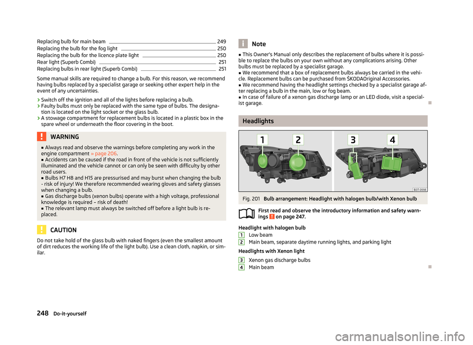
Headlights
Fig. 201
Bulb arrangement: Headlight with halogen bulb/with Xenon bulb
First read and observe the introductory information and safety warn- ings
on page 247.
Headlight with halogen bulb
Low beam
Main beam, separate daytime running lights, and parking light
Headlights with Xenon light Xenon gas discharge bulbs
Main beam
1234248Do-it-yourself
Page 252 of 274

Replacing the low beam bulbFig. 202
Halogen headlight: Changing the
bulb for the low beam
First read and observe the introductory information and safety warn-
ings on page 247.
›
Remove the rubber cover
1
» Fig. 201 on page 248.
›
Turn the plug with the bulb
A
» Fig. 202 as far as the stop in the direction of
the arrow.
›
Change the bulb.
›
Insert the bulb holder with the new bulb and turn in an anti-clockwise direction
as far as the stop.
›
Insert the rubber cover
1
.
Replacing bulb for main beam and daytime running lights
Fig. 203
Halogen headlight: Replacing
the bulb for main beam and sep-
arate daytime running lights
First read and observe the introductory information and safety warn- ings on page 247.
›
Remove the rubber cover
2
» Fig. 201 on page 248.
›Turn the bulb holder A
» Fig. 203 in the direction of the arrow as far as the
stop.›
Replace the bulb, insert the bulb holder with the new bulb and turn in the oppo-
site direction to that of the arrow as far as it goes.
›
Insert the rubber cover
2
.
Replacing bulb for main beam
Fig. 204
Headlights with Xenon light: Changing the bulb for the main beam
First read and observe the introductory information and safety warn-
ings
on page 247.
›
Unlock the protective cap in the direction of arrow
1
» Fig. 204 and remove.
›
Turn the plug with bulb
C
anti-clockwise to the stop and remove it.
›
Change the bulb.
›
Insert the bulb holder with the new bulb and turn in an anti-clockwise direction
as far as the stop.
›
Insert the protective cap in holder
2
and carefully push in.
The protective cover must engage firmly.
249Fuses and light bulbs
Page 267 of 274

Jump-starting234, 235
K
KESSY Information message
37
lock37
Lock / unlock the steering134
Starting the engine135
Switching off the engine136
Switching off the ignition136
Switching on the ignition135
unlock37
Key Starting the engine
132
Stopping the engine133
Knee airbag181
L
LEAVING HOME
55
Lever Main beam
53
Turn signal53
Windscreen wipers62
Licht COMING HOME / LEAVING HOME
55
Light Cockpit
57
Replacing bulbs247
Travel mode54
Light bulbs Rear light (Superb Combi)
251
Lighting Luggage compartment
84
Lights51
Adaptive headlights (AFS)54
Automatic driving lamp control53
Daylight running52
Fog lights55
Fog lights with the CORNER function55
Hazard warning light system56
Headlight beam adjustment51
Headlight flasher53
Instrument lighting51
Low beam lights51
Main beam53
Parking lights51, 57
Rear fog light55
Switching on and off51
Tourist lights54
Turn signal53
Warning lights14
Loads252
Lock Remote control
33
Vehicle key33
Locking Individual settings
35
KESSY34
Locking and unlocking the vehicle from the inside 36
Long-cargo channel
83
Low beam lights51
Luggage compartment84
Cover88
Emergency unlocking241
Fastening elements86
Fix floor covering87
Fixing nets86
Lighting84
Luggage net87
see boot lid40
Side pockets89
Unlocking the tailgate241
Variable loading floor92
Luggage compartment cover88
Luggage compartment lid39
Luggage net87
M
Main beam
53
Maintenance146
Decorative films199
Manual air conditioning adjusting
102
Recirculated air mode102
Manual gear changing see gear changing
138
Manually setting air conditioning Control elements
100
Materials defect liability5
MAXI DOT Main menu
28
see MAXI DOT display28
Settings29
MAXI DOT display28
MDI Installation in the storage compartment
79
MFA see multifunction display
25
Mirror Exterior mirrors
65
Mirrors Interior mirror
64
Vanity60
Mobile phone110, 113, 115
Connecting to the hands-free system113, 116
Modes of the automatic transmission140
Modifications193
Modifications and technical alterations Airbags
195
Service194
Spoiler195
Multifunction display Functions
25
Memory26
Multimedia126
AUX127
MDI127
264Index
Page 269 of 274

Fuses in the dash panel244
Fuses in the engine compartment246
Low beam bulb249
Wiper blades243
Replenishing Coolant
214
Engine oil212
Windscreen washer fluid209
Roof luggage rack Attachment points
97
Roof rack system96
Roof load97
Running-in The first 1500 km
142
Running in Brake pads
143
Engine142
Tyres143
S
Safe securing system
35
Safety169
Child safety186
Child safety seats186
Correct seated position170
Head restraints68
ISOFIX189
TOP TETHER190
Saving electrical energy143
Screens see Sun screen in the rear doors
61
Seals Taking care of your vehicle
199
Seat belt warning light
15
Seat belt height adjuster176
Seat belts173
Belt tensioners176
Cleaning203
fastening and unfastening175
Height adjustment176
Inertia reels176
The physical principle of a frontal collision174
Seat features70
Seats Armrest rear
73
Armtest, front72
Convenience features of passenger seat72
Electric adjustment67
Head restraints68
Heating70
Manually adjusting67
save69
Seat backrests73
Storing in memory of remote control key69
Ventilated front seats71
Seats and useful equipment66
Adjusting the seats66
see automatic gearbox Manual shifting of gears on the multifunction steering wheel
141
Selector lever see Using the selector lever
140
Service194
Service display30
Service intervals191
Setting the clock Clock
13
Shelves74
Shift Information on the selected gear
24
Recommended gear24
Shifting gears Driving and saving energy
144
Side airbag181
Side compartment in boot with battery90
Side compartments in the luggage compartment89
ski bag84
Sliding/tilting roof Close (Superb Combi)49
Closing47
Closing the sun screen (Superb Combi)49
Electric sliding/tilting roof47
Emergency operation242
Opening/closing the sun screen (Superb Combi)49
Opening and tilting47
Opening and tilting (Superb Combi)49
Operation47
Operation (Superb Combi)49
Snow chains226
Spare wheel224
Speedometer11
Speed symbol See Wheels
223
Spoiler195
START-STOP159
Manually activating/deactivating the system160
Operating conditions of the system160
Starting/shutting down the engine159
Starting and stopping the engine - KESSY133
Starting and stopping the engine using the key131
Starting engine Jump-starting
234
Starting the engine Jump-starting
235
Key132
see KESSY135
START STOP Information messages
161
Jump-starting236
Steering force assistance131
Steering lock / unlock see KESSY
134
Steering wheel130
Stopping the engine Key
133
Storage compartment in rear centre console82
Storage compartment on the passenger side80
266Index