wheel SKODA SUPERB 2013 2.G / (B6/3T) Owner's Manual
[x] Cancel search | Manufacturer: SKODA, Model Year: 2013, Model line: SUPERB, Model: SKODA SUPERB 2013 2.G / (B6/3T)Pages: 274, PDF Size: 17.31 MB
Page 7 of 274
General Maintenance
Car care191
Service intervals
191
Services, modifications, and technical
alterations
193
Washing your car
196
Taking care of your vehicle exterior
198
Taking care of the interior
201
Inspecting and replenishing
204
Fuel
204
Engine compartment
206
Engine oil
210
Coolant
212
Brake fluid
214
Vehicle battery
215
Wheels
220
Tyres and wheel rims
220
Winter operation
226
Do-it-yourself
Emergency equipment and self-help
227
Emergency equipment
227
Changing a wheel
229
Tyre repair
232
Jump-starting
234
Towing the vehicle
236
Radio remote control
238
Emergency unlocking/locking
240
Emergency operation of the sliding/tilting roof
241
Replacing windscreen wiper blades
242
Fuses and light bulbs
244
Fuses
244
Bulbs
247Technical data
Technical data252
Vehicle data
252
Index
4Table of Contents
Page 12 of 274
Using the system
Cockpit
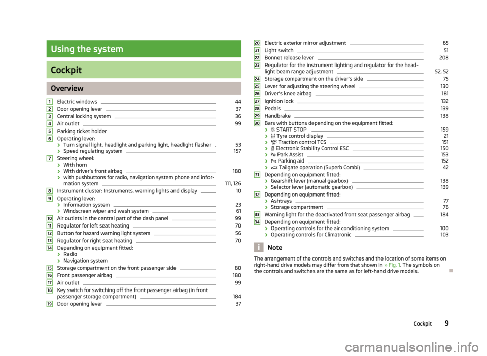
OverviewElectric windows
44
Door opening lever
37
Central locking system
36
Air outlet
99
Parking ticket holder
Operating lever:
› Turn signal light, headlight and parking light, headlight flasher
53
›
Speed regulating system
157
Steering wheel:
› With horn
› With driver’s front airbag
180
›with pushbuttons for radio, navigation system phone and infor-
mation system
111, 126
Instrument cluster: Instruments, warning lights and display
10
Operating lever:
› Information system
23
›Windscreen wiper and wash system
61
Air outlets in the central part of the dash panel
99
Regulator for left seat heating
70
Button for hazard warning light system
56
Regulator for right seat heating
70
Depending on equipment fitted:
› Radio
› Navigation system
Storage compartment on the front passenger side
80
Front passenger airbag
180
Air outlet
99
Key switch for switching off the front passenger airbag (in front
passenger storage compartment)
184
Door opening lever
3712345678910111213141516171819Electric exterior mirror adjustment65Light switch51
Bonnet release lever
208
Regulator for the instrument lighting and regulator for the head- light beam range adjustment
52, 52
Storage compartment on the driver's side
75
Lever for adjusting the steering wheel
130
Driver’s knee airbag
181
Ignition lock
132
Pedals
139
Handbrake
138
Bars with buttons depending on the equipment fitted:
›
START STOP
159
›
Tyre control display
21
›
Traction control TCS
151
›
Electronic Stability Control ESC
150
›
Park Assist
153
›
Parking aid
152
›
Tailgate operation (Superb Combi)
42
Depending on equipment fitted:
› Gearshift lever (manual gearbox)
138
›
Selector lever (automatic gearbox)
139
Depending on equipment fitted:
› Ashtrays
77
›
Storage compartment
76
Warning light for the deactivated front seat passenger airbag
184
Depending on equipment fitted:
› Operating controls for the air conditioning system
100
›Operating controls for Climatronic
103
Note
The arrangement of the controls and switches and the location of some items on
right-hand drive models may differ from that shown in » Fig. 1. The symbols on
the controls and switches are the same as for left-hand drive models.2021222324252627282930313233349Cockpit
Page 26 of 274
Information system
Driver information system
Introduction
This chapter contains information on the following subjects:
Using the information system
23
Ice warning
24
Gear recommendation
24
Door, boot lid or bonnet warning
25
Compass display
25
The information system provides the driver with alerts and messages about in-
dividual vehicle systems. This information and advice is shown in the instrument
cluster display or indicated by the lighting up of the corresponding warning light
in the instrument cluster.
The information system provides the following information.
› Ice warning
» page 24.
› Recommended gear
» page 24.
› Door, boot lid or bonnet warning
» page 25.
› Compass display
» page 25.
› Multi-function display (MFA)
» page 25.
› Warning against excessive speed
» page 27.
› MAXI DOT display
» page 28.
› Service interval display
» page 30.
› Auto Check Control
» page 13.
› Selector lever positions for an automatic gearbox
» page 140.WARNINGConcentrate fully at all times on your driving! As the driver, you are fully re-
sponsible for the operation of your vehicle.
Using the information system
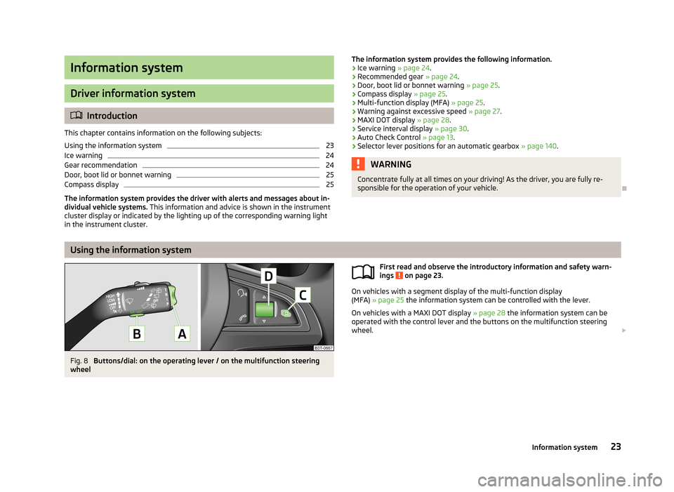
Fig. 8
Buttons/dial: on the operating lever / on the multifunction steering
wheel
First read and observe the introductory information and safety warn-
ings on page 23.
On vehicles with a segment display of the multi-function display
(MFA) » page 25 the information system can be controlled with the lever.
On vehicles with a MAXI DOT display » page 28 the information system can be
operated with the control lever and the buttons on the multifunction steering
wheel.
23Information system
Page 27 of 274
Description of the operationButton/wheelActionOperationApush up or down brieflySelect datapush up or down brieflySet data valuesPress and hold buttonCall up main menu of the MAXI DOT displayBpress brieflyShow datapress brieflyConfirm dataCPress and hold buttonCall up main menu of the MAXI DOT displaypress brieflyto go back one level in the menu of the MAXI DOT displayDTurn upwards or downwardsSelect dataTurn upwards or downwardsSet data valuespress brieflyShow datapress brieflyConfirm data
Ice warningFirst read and observe the introductory information and safety warn-ings
on page 23.
Prompt in the MAXI DOT display
If the outside temperature while driving drops to below +4°C, the following icon
appears on the display in front of the temperature display . An audible signal is
emitted.
If the outside temperature is already below +4°C when turning the ignition on,
the icon appears immediately. An audible signal is emitted.
Prompt in the segment display
If the outside temperature while driving drops to below +4°C, the temperature
display » page 26 , Outside temperature will show up with the following icon in
front
. An audible signal is emitted.
If the outside temperature is already below +4°C when turning the ignition on, the temperature display and the
icon appear immediately. An audible signal is
emitted.
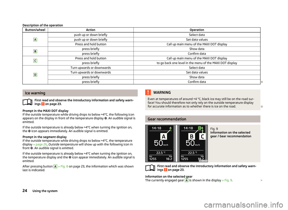
After pressing button
A
» Fig. 8 on page 23, the information which was shown
last is indicated.
WARNINGEven at temperatures of around +4 °C, black ice may still be on the road sur-
face! You should therefore not only rely on the outside temperature display
for accurate information as to whether there is ice on the road.
Gear recommendation
Fig. 9
Information on the selected
gear / Gear recommendation
First read and observe the introductory information and safety warn-
ings on page 23.
Information on the selected gear
The currently engaged gear
A
is shown in the display » Fig. 9.
24Using the system
Page 29 of 274
WARNING■Concentrate fully at all times on your driving! As the driver, you are fully re-
sponsible for the operation of your vehicle.■
Even at temperatures of around +4 °C, black ice may still be on the road sur-
face! You should therefore not only rely on the outside temperature display
for accurate information as to whether there is ice on the road.
Note
■ In certain national versions the displays appear in the Imperial system of meas-
ures.■
If the display of the second speed is activated in mph, the current speed is not
indicated in km/h on the display.
■
The amount of fuel consumed will not be indicated.
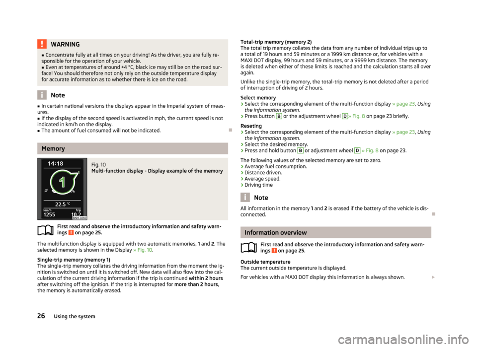
Memory
Fig. 10
Multi-function display - Display example of the memory
First read and observe the introductory information and safety warn-
ings on page 25.
The multifunction display is equipped with two automatic memories, 1 and 2. The
selected memory is shown in the Display » Fig. 10.
Single-trip memory (memory 1)
The single-trip memory collates the driving information from the moment the ig- nition is switched on until it is switched off. New data will also flow into the cal-
culation of the current driving information if the trip is continued within 2 hours
after switching off the ignition. If the trip is interrupted for more than 2 hours,
the memory is automatically erased.
Total-trip memory (memory 2)
The total trip memory collates the data from any number of individual trips up to
a total of 19 hours and 59 minutes or a 1999 km distance or, for vehicles with a
MAXI DOT display, 99 hours and 59 minutes, or a 9999 km distance. The memory is deleted when either of these limits is reached and the calculation starts all over
again.
Unlike the single-trip memory, the total-trip memory is not deleted after a period of interruption of driving of 2 hours.
Select memory›
Select the corresponding element of the multi-function display » page 23, Using
the information system .
›
Press button
B
or the adjustment wheel
D
» Fig. 8 on page 23 briefly.
Reseting
›
Select the corresponding element of the multi-function display » page 23, Using
the information system .
›
Select the desired memory.
›
Press and hold button
B
or adjustment wheel
D
» Fig. 8 on page 23.
The following values of the selected memory are set to zero. › Average fuel consumption.
› Distance driven.
› Average speed.
› Driving time
Note
All information in the memory
1 and 2 is erased if the battery of the vehicle is dis-
connected.
Information overview
First read and observe the introductory information and safety warn-
ings
on page 25.
Outside temperature
The current outside temperature is displayed.
For vehicles with a MAXI DOT display this information is always shown.
26Using the system
Page 55 of 274
Lights and visibility
Turning the rotary switch from position to gradually activates the headlight
beam adjustment, thereby shortening the beam of light » Fig. 30, position B
.
The positions of the width of illumination correspond approximately to the fol-
lowing car load.
Front seats occupied, boot empty
All seats occupied, boot empty
All seats occupied, boot loaded
Driver seat occupied, boot loaded
Instrument lighting
Turning the rotary switch
when the lights are switched on adjusts the bright-
ness of the instrument lighting » Fig. 30, position
C
.
The instruments are also illuminated when the side light, low or high beam light is switched on.
WARNINGAlways adjust the headlight beam to satisfy the following conditions.■The vehicle does not dazzle other road users, especially oncoming vehicles.■
The beam range is sufficient for safe driving.
Note
■ We recommend you adjust the headlight beam when the low beam is switched
on.■
The Bi-Xenon bulbs adapt automatically to the load and driving state of the ve-
hicle when the ignition is switched on and when driving. Vehicles that are equip- ped with Bi-Xenon headlights do not have a manual headlight range adjustment
control.
■
The low beam continues to shine while the ignition is switched on and the light
switch is in the position or . After switching off the ignition, the low beam
is switched off automatically and only the side lights come on. The side light goes
out after the ignition key is removed.
■
If there is a fault in the light switch, the low beam comes on automatically.
Daylight running lights (DAY LIGHT)
First read and observe the introductory information and safety warn-
ings
on page 51.
The daytime running lights function provides the lighting of the front of the vehi-
cle.
Switching on daytime running lights
›
The light switch is in position
A
or turn » Fig. 30 on page 51.
Deactivating the function daylight driving lights
›
Pull the turn signal and main beam lever to the steering wheel and push down-
wards » Fig. 31 on page 53.
›
At the same time switch on the ignition and hold the lever down in this position
for at least 3 seconds.
Activating the function daylight driving lights
›
Pull the turn signal and main beam lever to the steering wheel and push up- wards » Fig. 31 on page 53.
›
At the same time switch on the ignition and hold the lever down in this position
for at least 3 seconds.
The daytime running lights can be activated or deactivated via the Maxi DOT dis-
play in the menu item DRL » page 29 .
The daytime running lights are switched on automatically if the following condi- tions are met:
The ignition is switched on.
The daylight driving lights function is activated.
The light switch is in the position
or
» Fig. 30 on page 51.
Note
When the daytime running light is switched on, the side lights (neither at the
front or rear) and the number plate lights are not lit.
52Using the system
Page 58 of 274
Fog lightsFig. 33
Light switch
First read and observe the introductory information and safety warn-
ings on page 51.
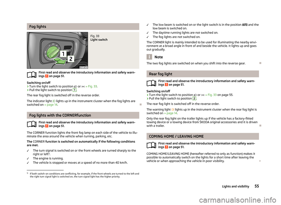
Switching on/off
›
Turn the light switch to position
or
» Fig. 33 .
›
Pull the light switch to position
1
.
The rear fog light is switched off in the reverse order.
The indicator light
lights up in the instrument cluster when the fog lights are
switched on » page 14.
Fog lights with the CORNERfunction
First read and observe the introductory information and safety warn-ings
on page 51.
The CORNER function lights the front fog lamp on each side of the vehicle to illu-
minate the area around the vehicle when turning, parking, etc.
The CORNER function is switched on automatically if the following conditions
are met.
The turn signal is switched on or the front wheels are turned sharply to the
right or left 1)
.
The engine is running.
The vehicle is stopped or moves at a speed of no more than 40 km/h.
The low beam is switched on or the light switch is in the position and the
low beam is switched on.
The daytime running lights are not switched on. The fog lights are not switched on.
The CORNER light is mainly intended to be used for illuminating the nearby envi-
ronment at a broad angle in front of and beside the vehicle. It lights up and goes out gradually.
Note
The two fog lights are switched on when you shift into the reverse gear.
Rear fog light
First read and observe the introductory information and safety warn-
ings
on page 51.
Switching on/off
›
Turn the light switch to position
or
» Fig. 33 on page 55.
›
Pull the light switch to position
2
.
The rear fog light is switched off in the reverse order.
The warning light
lights up in the instrument cluster when the rear fog light is
switched on » page 14.
Only the rear fog light on the trailer lights up if the vehicle has a factory-fitted
towing device or a towing device from ŠKODA original accessories and it is driven
with a trailer.
COMING HOME / LEAVING HOME
First read and observe the introductory information and safety warn-ings
on page 51.
COMING HOME/LEAVING HOME (hereafter referred to only as function) makes it
possible to automatically switch on the lights for a short time after leaving the
vehicle or when approaching the vehicle in poor visibility.
1)
If both switch-on conditions are conflicting, for example, if the front wheels are turned to the left and
the right turn signal light is switched on, the turn signal light has the higher priority.
55Lights and visibility
Page 67 of 274
CAUTIONNever mechanically fold in or fold back the exterior mirrors with the fold-in func-
tion by hand as this will damage the electric drive.
Note
■
Automatic mirror dimming operates only properly if the sun screen for the rear
window in the housing on the boot cover is not in use or the light striking the in- terior rear-view mirror is not affected by other objects.■
If the automatic interior mirror dimming is switched off, the exterior mirror dim-
ming is also switched off.
■
The mirror heater only operates when the engine is running and up to an out-
side temperature of +35 ℃.
■
Do not touch the surface of the exterior mirrors if the exterior mirror heater is
switched on.
■
If the electrical exterior mirror setting fails at any time, the mirrors can be adjus-
ted by hand by pressing on the edge of the mirror surface.
■
Contact a specialist garage if there is a fault with the power setting function for
the exterior mirrors.
Interior mirror
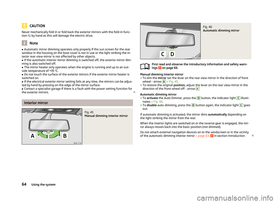
Fig. 45
Manual dimming interior mirror
Fig. 46
Automatic dimming mirror
First read and observe the introductory information and safety warn-
ings on page 63.
Manual dimming interior mirror
›
To dim the mirror set the lever on the rear view mirror in the direction of front
wheel - arrow
A
» Fig. 45 .
›
To restore the original position, adjust the lever on the rear view mirror in the
direction of the front wheel off - arrow
B.
Automatic dimming mirror
›
To activate the Auto Dimmer, press the
D
button, the indicator light
C
illumi-
nates » Fig. 46 .
›
To disable auto-dimming, press the
D
button again, the indicator light
C
goes
out.
If automatic dimming is activated, the mirror dims automatically depending on
the light striking the mirror from the rear.
When the interior lights are switched on or the reverse gear is engaged, the mir-ror always moves back into the basic position (not dimmed).
Do not attach external navigation devices on to the windscreen or in the vicinity
of the automatic dimming interior mirror » page 63,
in section Introduction .
64Using the system
Page 69 of 274

Seats and useful equipment
Adjusting the seats
Introduction
This chapter contains information on the following subjects:
Manually adjusting the front seats
67
Electric front seat adjustment
67
Head restraints
68
Memory function of the electrically adjustable seat
69
Memory function of the remote control key
69
The driver's seat should be adjusted in such a way that the pedals can be fully
pressed to the floor with slightly bent legs.
The seat backrest on the driver's seat should be adjusted in such a way that the
upper point of the steering wheel can be easily reached with slightly bent arms.
Correct adjustment of the seats is particularly important:
› for safely and quickly reaching the controls;
› for a relaxed body position that reduces fatigue;
› for achieving maximum protection from the seat belts and the airbag system.
WARNINGGeneral information■Caution when adjusting the seat! You may suffer injuries or bruises as a re-
sult of adjusting the seat without paying proper attention.■
The electric front seat adjustment is still functional if the ignition is switch-
ed off (even with the ignition key removed). Therefore, children should never
be left unattended in the vehicle.
■
The seat backrests must not be tilted too far back when driving, as this will
impair the function of the seat belts and of the airbag system – risk of injury!
■
Never carry more people than the number of seats in the vehicle.
■
Each occupant must correctly fasten the seat belt belonging to the seat.
Children must be fastened » page 186, Transporting children safely with a
suitable restraint system.
WARNING (Continued)■ The front seats and head restraints must be adjusted to match the body
size at all times and the seat belt must always be fastened properly to provide
the most effective levels of protection to the passengers.■
Do not carry any objects on the front passenger seat except objects de-
signed for this purpose (e.g. child seats) – risk of accident!
WARNINGInformation for the driver■Only adjust the driver's seat when the vehicle is stationary – risk of accident!■
Maintain a distance of at least 25 cm from the steering wheel, and a dis-
tance of at least 10 cm between the legs and the dash panel at the height of
the knee airbag. Not maintaining this minimum distance will mean that the
airbag system will not be able to properly protect you - hazard!
■
Ensure that there are no objects in the driver's footwell, as these may get
caught in the pedal apparatus when driving or braking » page 139. You would
then no longer be able to operate the clutch, brake or accelerate.
WARNINGInformation for the front seat passenger■Maintain a distance of at least 25 cm to the dash panel. Not maintaining this
minimum distance will mean that the airbag system will not be able to proper-
ly protect you - hazard!■
Always keep your feet in the footwell when the car is being driven - never
place your feet on the instrument panel, out of the window or on the surfaces of the seats. You will be exposed to increased risk of injury if it becomes nec-
essary to apply the brake or in the event of an accident. If an airbag is de-
ployed, you may suffer fatal injuries when adopting an incorrect seated posi- tion!
Note
■ After a certain time, play can develop within the adjustment mechanism of the
backrest angle.■
For safety reasons, it is not possible to store the seat position in the electric
seat memory and remote control key memory if the inclination angle of the seat
backrest is more than 102° in relation to the seat cushion.
■
Each time you store the position of the electrically adjustable driver's seat and
exterior mirrors, the existing setting is deleted.
66Using the system
Page 70 of 274
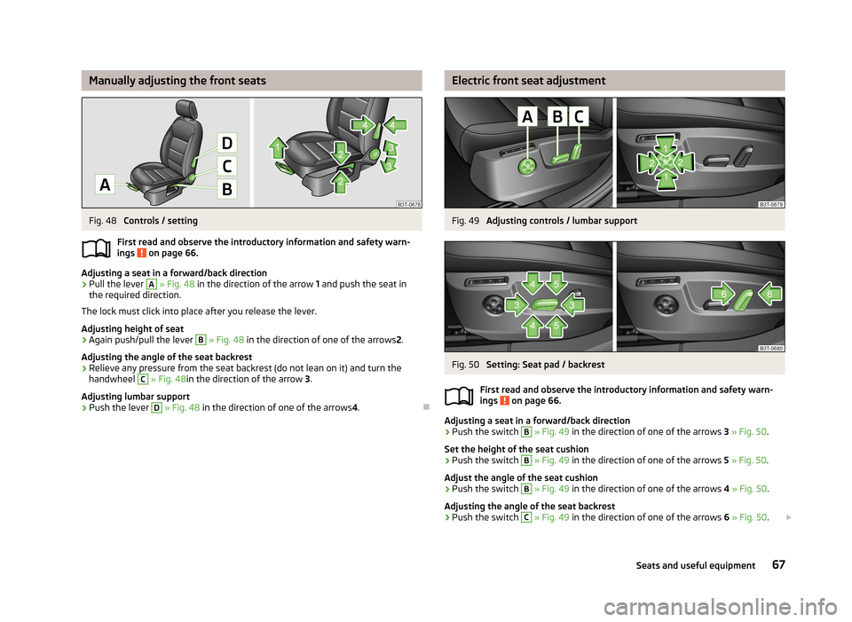
Manually adjusting the front seatsFig. 48
Controls / setting
First read and observe the introductory information and safety warn- ings
on page 66.
Adjusting a seat in a forward/back direction
›
Pull the lever
A
» Fig. 48 in the direction of the arrow 1 and push the seat in
the required direction.
The lock must click into place after you release the lever.
Adjusting height of seat
›
Again push/pull the lever
B
» Fig. 48 in the direction of one of the arrows 2.
Adjusting the angle of the seat backrest
›
Relieve any pressure from the seat backrest (do not lean on it) and turn the handwheel
C
» Fig. 48 in the direction of the arrow 3.
Adjusting lumbar support
›
Push the lever
D
» Fig. 48 in the direction of one of the arrows 4.
Electric front seat adjustmentFig. 49
Adjusting controls / lumbar support
Fig. 50
Setting: Seat pad / backrest
First read and observe the introductory information and safety warn-
ings
on page 66.
Adjusting a seat in a forward/back direction
›
Push the switch
B
» Fig. 49 in the direction of one of the arrows 3 » Fig. 50 .
Set the height of the seat cushion
›
Push the switch
B
» Fig. 49 in the direction of one of the arrows 5 » Fig. 50 .
Adjust the angle of the seat cushion
›
Push the switch
B
» Fig. 49 in the direction of one of the arrows 4 » Fig. 50 .
Adjusting the angle of the seat backrest
›
Push the switch
C
» Fig. 49 in the direction of one of the arrows 6 » Fig. 50 .
67Seats and useful equipment