height SKODA SUPERB 2014 2.G / (B6/3T) User Guide
[x] Cancel search | Manufacturer: SKODA, Model Year: 2014, Model line: SUPERB, Model: SKODA SUPERB 2014 2.G / (B6/3T)Pages: 246, PDF Size: 17.16 MB
Page 97 of 246
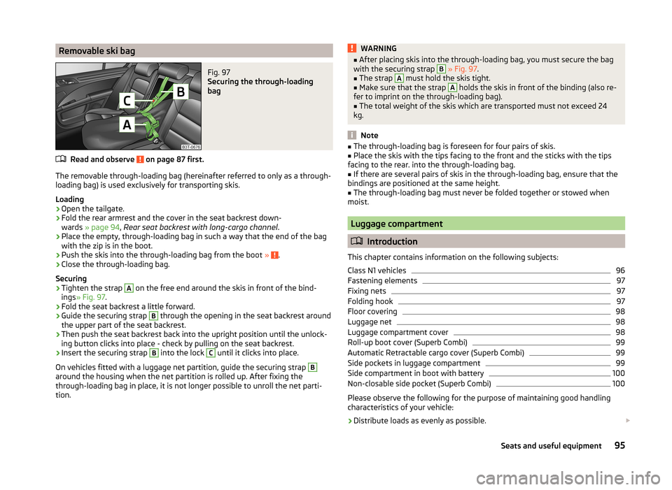
Removable ski bagFig. 97
Securing the through-loading
bag
Read and observe on page 87 first.
The removable through-loading bag (hereinafter referred to only as a through-
loading bag) is used exclusively for transporting skis.
Loading
›
Open the tailgate.
›
Fold the rear armrest and the cover in the seat backrest down-
wards » page 94 , Rear seat backrest with long-cargo channel .
›
Place the empty, through-loading bag in such a way that the end of the bag
with the zip is in the boot.
›
Push the skis into the through-loading bag from the boot » .
›
Close the through-loading bag.
Securing
›
Tighten the strap
A
on the free end around the skis in front of the bind-
ings » Fig. 97 .
›
Fold the seat backrest a little forward.
›
Guide the securing strap
B
through the opening in the seat backrest around
the upper part of the seat backrest.
›
Then push the seat backrest back into the upright position until the unlock-
ing button clicks into place - check by pulling on the seat backrest.
›
Insert the securing strap
B
into the lock
C
until it clicks into place.
On vehicles fitted with a luggage net partition, guide the securing strap
B
around the housing when the net partition is rolled up. After fixing the
through-loading bag in place, it is not longer possible to unroll the net parti-
tion.
WARNING■ After placing skis into the through-loading bag, you must secure the bag
with the securing strap B » Fig. 97 .■
The strap
A
must hold the skis tight.
■
Make sure that the strap
A
holds the skis in front of the binding (also re-
fer to imprint on the through-loading bag).
■
The total weight of the skis which are transported must not exceed 24
kg.
Note
■ The through-loading bag is foreseen for four pairs of skis.■Place the skis with the tips facing to the front and the sticks with the tips
facing to the rear. into the through-loading bag.■
If there are several pairs of skis in the through-loading bag, ensure that the
bindings are positioned at the same height.
■
The through-loading bag must never be folded together or stowed when
moist.
Luggage compartment
Introduction
This chapter contains information on the following subjects:
Class N1 vehicles
96
Fastening elements
97
Fixing nets
97
Folding hook
97
Floor covering
98
Luggage net
98
Luggage compartment cover
98
Roll-up boot cover (Superb Combi)
99
Automatic Retractable cargo cover (Superb Combi)
99
Side pockets in luggage compartment
99
Side compartment in boot with battery
100
Non-closable side pocket (Superb Combi)
100
Please observe the following for the purpose of maintaining good handling
characteristics of your vehicle:
›
Distribute loads as evenly as possible.
95Seats and useful equipment
Page 109 of 246
WARNING (Continued)■Distribute the load evenly over the roof rack system.■When transporting heavy objects or objects which take up a large area on
the roof rack system, the handling of the car may change as a result of the
displacement of the centre of gravity. The style of driving and speed must
therefore be adapted to the current circumstances.■
Avoid abrupt and sudden driving/braking manoeuvres.
■
Adjust the speed and driving style to the visibility, weather, road and traf-
fic conditions.
■
The permissible roof load, permissible axle loads and permissible total ve-
hicle weight must not be exceeded under any circumstances – risk of acci-
dent!
CAUTION
■ Only roof racks from the ŠKODA Original Accessories range should be used.■When dealing with roof racks, the installation instructions supplied with the
roof luggage rack system must be observed.■
On models fitted with a power sliding/tilting roof or a panoramic sliding roof,
ensure that the opened sliding/tilting roof or the panoramic sliding roof does
not strike any items of luggage transported on the roof.
■
Ensure that the boot lid does not hit the roof load when opened.
■
The height of the vehicle changes after mounting a roof luggage rack system
and the load that is secured to it. Compare the vehicle height with available
clearances, such as underpasses and garage doors.
■
Always remove the roof luggage rack system before entering an automated
car wash.
■
Ensure the roof aerial is not impaired by the secured load.
For the sake of the environment
The increased aerodynamic drag results in a higher fuel consumption.Attachment points
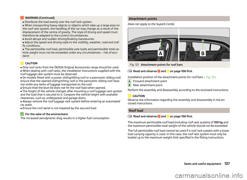
Does not apply to the Superb Combi.Fig. 121
Attachment points for roof bars
Read and observe
and on page 106 first.
Installation position of the attachment points for roof bars » Fig. 121:
Forward attachment point
Rear attachment point
Perform the assembly and disassembly according to the enclosed instructions.
CAUTION
Observe the information regarding the assembly and disassembly in the en-
closed instructions.
Roof load
Read and observe
and on page 106 first.
The maximum permissible roof load (including roof rack system) of 100 kg and
the maximum permissible total weight of the vehicle should not be exceeded.
The full permissible roof load cannot be used if a roof rack system with a lower
load carrying capacity is used. In this case, the roof rack system must only be
loaded up to the maximum weight limit specified in the fitting instructions.
AB107Seats and useful equipment
Page 111 of 246
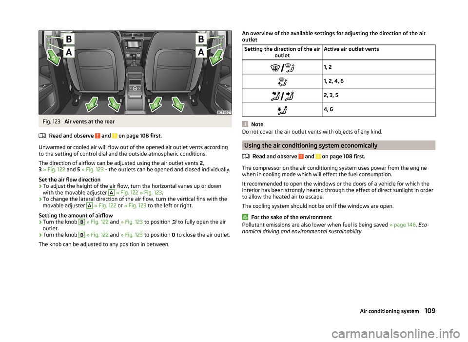
Fig. 123
Air vents at the rear
Read and observe
and on page 108 first.
Unwarmed or cooled air will flow out of the opened air outlet vents according
to the setting of control dial and the outside atmospheric conditions.
The direction of airflow can be adjusted using the air outlet vents 2,
3 » Fig. 122 and 5 » Fig. 123 - the outlets can be opened and closed individually.
Set the air flow direction
›
To adjust the height of the air flow, turn the horizontal vanes up or down
with the movable adjuster
A
» Fig. 122 » Fig. 123 .
›
To change the lateral direction of the air flow, turn the vertical fins with the
movable adjuster
A
» Fig. 122 or » Fig. 123 to the left or right.
Setting the amount of airflow
›
Turn the knob
B
» Fig. 122 and » Fig. 123 to position
to fully open the air
outlet.
›
Turn the knob
B
» Fig. 122 and » Fig. 123 to position 0 to close the air outlet.
The knob can be adjusted to any position in between.
An overview of the available settings for adjusting the direction of the air
outletSetting the direction of the air outletActive air outlet vents1, 21, 2, 4, 6 2, 3, 54, 6
Note
Do not cover the air outlet vents with objects of any kind.
Using the air conditioning system economically
Read and observe
and on page 108 first.
The compressor on the air conditioning system uses power from the engine
when in cooling mode which will effect the fuel consumption.
It recommended to open the windows or the doors of a vehicle for which the
interior has been strongly heated through the effect of direct sunlight in order
to allow the heated air to escape.
The cooling system should not be on if the windows are open.
For the sake of the environment
Pollutant emissions are also lower when fuel is being saved » page 146, Eco-
nomical driving and environmental sustainability .109Air conditioning system
Page 168 of 246
CAUTION■If the lever is held firm and not pushed downwards as far as it can go, it will
go back up after the ball head is removed and will not latch into the ready po-
sition. The tow bar will then need to be brought into this position before the
next time it is fitted.■
Stow the ball head in the ready position with the key inserted in the box.
When doing so, make the side opposite to the inserted key face downwards –
there is a risk of damaging the key.
■
Do not use excessive force when handling the operating lever (e.g. do not
step on it).
Note
■ We recommend putting the protective cover onto the ball head before re-
moving the tow bar.■
Clean any dirt from the tow bar before stowing it away in the box with the
vehicle tool kit.
Use and care
Read and observe
and on page 163 first.
Close the mounting recess with the cover to prevent any dirt from getting in.
Always check the tow bar before hitching a trailer. Apply suitable grease
where necessary.
Use the protective cover when stowing away the tow bar, in order to stop the
boot from getting dirty.
In the event of dirt, clean the surfaces of the mounting recess and treat with a
suitable preservative.
CAUTION
Apply grease to the upper part of the mounting recess. Make sure you do not
remove any grease.
Trailer
Introduction
This chapter contains information on the following subjects:
Loading a trailer
166
Driving with a trailer
167Trailer stabilisation (TSA)168Anti-theft alarm system168WARNINGAlways drive particularly carefully with the trailer.
Loading a trailer
Read and observe
on page 166 first.
The vehicle/trailer combination must be balanced, whereby the maximum per-
missible drawbar load must be utilised. If the drawbar load is too low, it jeop-
ardises the performance of the vehicle/trailer combination.
Distribution of the load
Distribute the load in the trailer in such a way that heavy items are located as
close to the axle as possible. Secure the items from slipping.
The distribution of the weight is very poor if your vehicle is unladen and the
trailer is laden. Maintain a particularly low speed if you cannot avoid driving
with this combination.
Tyre pressure
Correct the tyre inflation pressure on your vehicle for a “full load” » page 194,
Service life of tyres .
Trailer load
The permissible trailer load must not be exceeded under any circumstan- ces » page 224 , Technical data .
The trailer loads specified apply only to altitudes up to 1 000 metres above
mean sea level.
The engine output falls as altitude increases, as does the vehicle's climbing
power. Therefore, for every additional 1000 m in height (or part), the maximum
permissible towed weight must be reduced by 10%.
The towed weight is made up of the actual weights of the loaded towing vehi-
cle and the loaded trailer.
The trailer and drawbar load information on the type plate of the towing de-
vice is merely a test value for the towing device. The vehicle-specific values
are detailed in the vehicle documents.
166Driving
Page 185 of 246
WARNING (Continued)■Avoid short circuits in the electrical system - particularly on the vehicle's
battery.■
Always make sure that no jewellery, loose clothing or long hair can get
caught in rotating engine parts – risk to life! Always remove any jewellery,
tie back long hair and wear tight fitting clothing before completing any
work.
WARNINGInformation for working on the fuel system or the electrical system■Always disconnect the vehicle battery from the electrical system.■
Do not smoke.
■
Never work near open flames.
■
Always have a functioning fire extinguisher nearby.
WARNING■ Read and observe the information and warning instructions on the fluid
containers.■
Keep the working fluids in sealed original containers and safe from peo-
ple who are not completely independent, e.g. children.
■
If you intend to work underneath the vehicle, you must secure the vehicle
from rolling away and support it with suitable supporting blocks; the car
jack is not sufficient – risk of injury!
CAUTION
Always top up using the correct specification of fluids. This may result in major
operating problems and also vehicle damage!
For the sake of the environment
In view of the requirements for the environmentally friendly disposal of fluids and the special tools and knowledge required for such work, we recommend
that fluids be changed by a specialist garage.
Note
■ Please consult a specialist garage for any questions relating to fluids.■Fluids with the proper specifications can be purchased from the ŠKODA Origi-
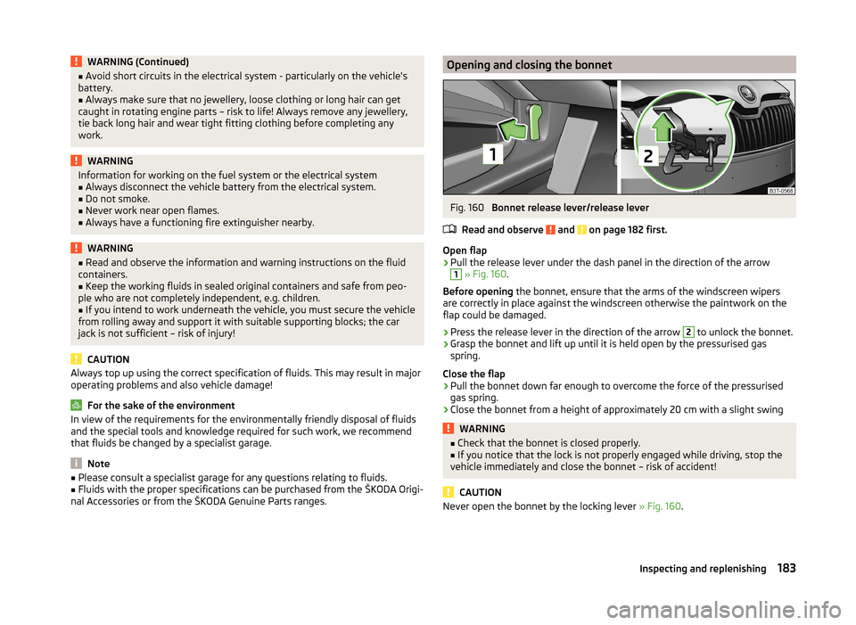
nal Accessories or from the ŠKODA Genuine Parts ranges.Opening and closing the bonnetFig. 160
Bonnet release lever/release lever
Read and observe
and on page 182 first.
Open flap
›
Pull the release lever under the dash panel in the direction of the arrow
1
» Fig. 160 .
Before opening the bonnet, ensure that the arms of the windscreen wipers
are correctly in place against the windscreen otherwise the paintwork on the
flap could be damaged.
›
Press the release lever in the direction of the arrow
2
to unlock the bonnet.
›
Grasp the bonnet and lift up until it is held open by the pressurised gas
spring.
Close the flap
›
Pull the bonnet down far enough to overcome the force of the pressurised
gas spring.
›
Close the bonnet from a height of approximately 20 cm with a slight swing
WARNING■ Check that the bonnet is closed properly.■If you notice that the lock is not properly engaged while driving, stop the
vehicle immediately and close the bonnet – risk of accident!
CAUTION
Never open the bonnet by the locking lever » Fig. 160.183Inspecting and replenishing
Page 198 of 246
Where possible, replace tyres by axle. Always fit the tyres with the deeper
tread depth to the front wheels.
Explanation of tyre markings
205/55 R 16 94 V
What this means is:205Tyre width in mm » Fig. 168 on page 194 - 55Height/width ratio in % » Fig. 168 on page 194 - RCode letter for the type of tyre – Radial » Fig. 168 on page 194 -
16Diameter of wheel in inches » Fig. 168 on page 194 - 94Load index » VSpeed symbol »
The date of manufacture is stated on the tyre wall (possibly on the inside). e.g.
DOT ... 11 14...
means, for example, that the tyre was manufactured in the 11th week of 2014.
Load index
This indicates the maximum permissible load for each individual tyre.
615 kg
630 kg
650 kg
670 kg
690 kg
730 kg
775 kg
Speed symbol
This indicates the maximum permissible vehicle speed with fitted tyres in each
category.
130 km/h
160 km/h
170 km/h
180 km/h
190 km/h
200 km/h
210 km/h
91929394959799MQRSTUH240 km/h
270 km/h
300 km/h
CAUTION
The information about the load index and the speed symbol is listed in your
vehicle documents.
Unidirectional tyres
Read and observe
and on page 193 first.
The direction of rotation of the tyres is marked by arrows on the wall of the
tyre .
The indicated direction of rotation must be adhered to in order to ensure the
optimal characteristics of these tyres.
These characteristics mainly relate to the following: › Increased driving stability.
› Reduced risk of aquaplaning.
› Reduced tyre noise and tyre wear.
Tyre pressure monitor
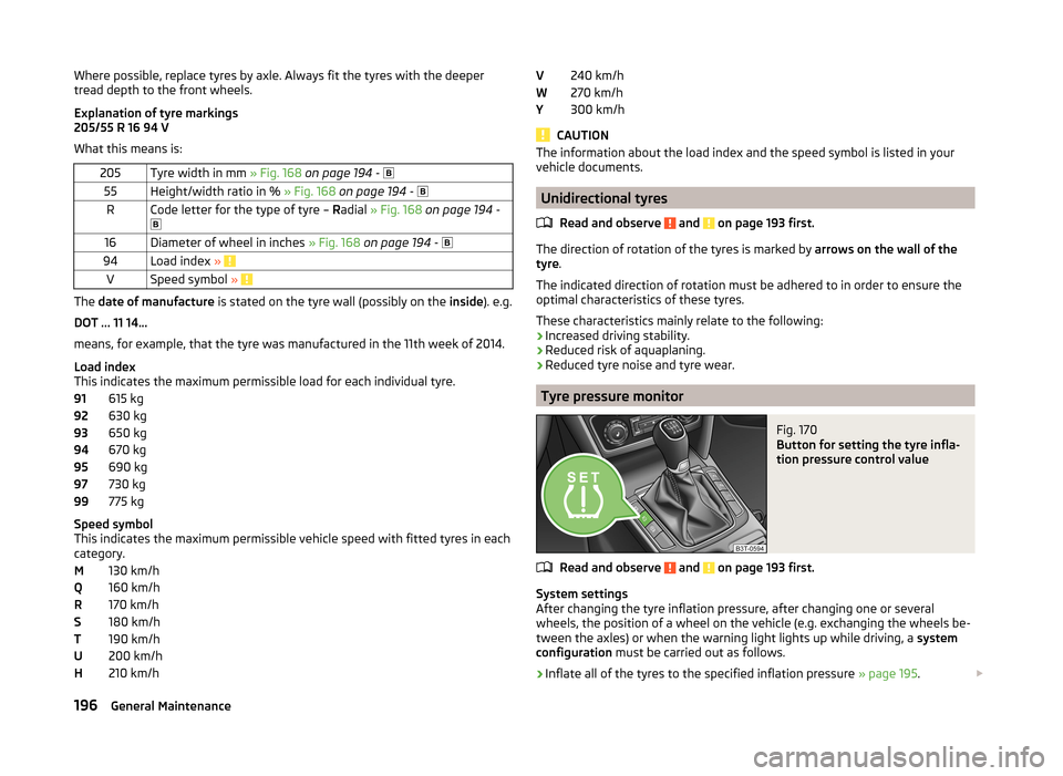
Fig. 170
Button for setting the tyre infla-
tion pressure control value
Read and observe and on page 193 first.
System settings
After changing the tyre inflation pressure, after changing one or several
wheels, the position of a wheel on the vehicle (e.g. exchanging the wheels be-
tween the axles) or when the warning light lights up while driving, a system
configuration must be carried out as follows.
›
Inflate all of the tyres to the specified inflation pressure » page 195.
V
WY196General Maintenance
Page 228 of 246
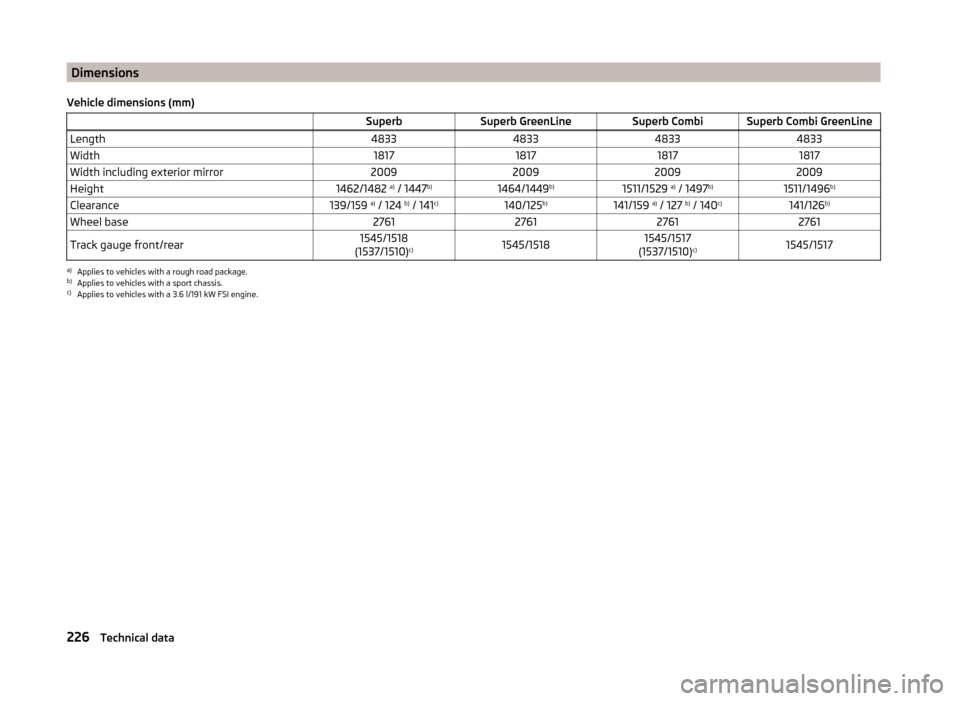
Dimensions
Vehicle dimensions (mm) SuperbSuperb GreenLineSuperb CombiSuperb Combi GreenLineLength4833483348334833Width1817181718171817Width including exterior mirror2009200920092009Height1462/1482 a)
/ 1447 b)1464/1449 b)1511/1529 a)
/ 1497 b)1511/1496 b)Clearance139/159 a)
/ 124 b)
/ 141 c)140/125 b)141/159 a)
/ 127 b)
/ 140 c)141/126 b)Wheel base2761276127612761Track gauge front/rear1545/1518
(1537/1510) c)1545/15181545/1517
(1537/1510) c)1545/1517a)
Applies to vehicles with a rough road package.
b)
Applies to vehicles with a sport chassis.
c)
Applies to vehicles with a 3.6 l/191 kW FSI engine.
226Technical data
Page 234 of 246
Index
A
Abroad Driving abroad
150
Unleaded petrol150
ABS Operation
152
Warning light36
Accessories169
Adaptive headlights (AFS)68
Adjust Auxiliary heating (auxiliary heating and ventila-tion)
117
Adjusting Belt height
13
Exterior mirrors78
Head restraints81
Interior mirror77
Manual air conditioning112
Seats79, 80
Steering wheel8
Adjusting the seats7, 79
Adjustment Headlight beam
66
Aerial173
See windows175
AFS68
Warning light36
Airbag14
Deactivating19
Deactivating the front passenger airbag20
Deployment14
Front airbag15
Head airbag18
Indicator light38
Knee airbag16
Modifications and damage to the airbag system 171 Side airbag
17
Airbag system14
Air conditioning system108
Air outlets108
Climatronic113
Manual air conditioning system110
Air outlets108
Air recirculation Climatronic
115
Alarm Switching off
54
Triggering54
Anti-theft alarm system Activating/deactivating
54
Trailer168
Antilock brake system (ABS)152
Armrest front
85
rear85, 94
Artificial leather178
Ashtray89
ASR Warning light
35
Assist systems151
ABS36, 152
ASR35
Cruise Control System158
DSR152
EDL152
ESC35, 151
HBA152
HHC153
Park assist154
Parking aid153
START-STOP159
TCS152
Auto Check Control31
Automatic driving lamp control68
Automatic gearbox142
Selector lever-emergency unlocking213
Starting-off and driving144
Tiptronic143
Using the selector lever142
Automatic gearbox modes142
Automatic load deactivation193
Automatic retractable cargo cover (Superb Combi))
99
Automatic transmission Kickdown
144
Malfunction144
Selector lever lock143
AUX Installation in the storage compartment
90
Auxiliary heating (auxiliary heating and ventila- tion)
116
Adjust117
Radio remote control118
Switching on/off117
Avoiding damage to the vehicle Driving through water
149
Avoiding damage to your vehicle149
B
Ball head Check fitting
165
Fitting164
Ready position164
Removing165
Battery In the remote control key
211
iReplace the remote control of the auxiliary heater (parking heater)
211
Belts10
Belt tensioners13
Bonnet Closing
183
Opening183
Warning light34
Boot Automatic retraction (Superb Combi)
99
Extending variable loading floor103
232Index
Page 241 of 246
Seat beltwarning light33
Seat belts10
Belt tensioners13
Cleaning178
fastening and unfastening12
Height adjustment13
Inertia reels13
The physical principle of a frontal collision11
Seat features83
Seats Armrest rear
85
Armtest, front85
Convenience features of passenger seat85
Electric adjustment80
Head restraints81
Heating83
Manually adjusting80
save82
Seat backrests85
Storing in memory of remote control key82
Ventilated front seats84
Seats and useful equipment79
Adjusting the seats79
see automatic gearbox Manual shifting of gears on the multifunctionsteering wheel
143
Selector lever Refer to Selector lever
142
Selector lever lock / starter (system KESSY) Warning light
39
Service170
Service interval display46
Service intervals169
Setting30
Setting the30
Shelves86
Shifting gears Driving and saving energy
146
Side airbag17
Side compartment in boot with battery100
Side compartments in the luggage compart- ment
99
ski bag95
Sliding/tilting roof Close (Superb Combi)
64
Closing62
Closing the sun screen (Superb Combi)64
Electric sliding/tilting roof62
Emergency operation213
Opening/closing the sun screen (Superb Combi) 64
Opening and tilting
62
Opening and tilting (Superb Combi)64
Operation62
Operation (Superb Combi)64
Snow chains199
Spare wheel197
Speedometer29
see speedometer29
Speed symbol See Wheels
196
Spoiler171
START-STOP159
Manually deactivating/activating the system161
Operating conditions of the system160
operation in vehicles with automatic gearbox 160
operation in vehicles with manual gearbox
160
system-related automatic start-up161
Starting and stopping the engine - KESSY137
Starting and stopping the engine using the key 135
Starting engine Jump-starting
207
Starting the engine Jump-starting
207
Key136
see KESSY139
START STOP Information messages
161
Jump-starting208
Steering lock / unlock see KESSY138
Steering wheel8
Stopping the engine Key
137
Storage compartment in rear centre console93
Storage compartment on the passenger side92
Storage compartments86
Storage compartment under the passenger seat
92
Storage pockets on the front seats93
Storing skis94
Sun screen74
Sun screen in the rear doors74
Sun visors74
Switch see Ignition
136
Switching lights on and off66
Switching off the engine see KESSY
139
Switch off ignition Refer to KESSY
138
Switch on ignition Refer to KESSY
138
Synchronous adjustment of the rear-view mir- ror
78
T
Tailgate TwinDoor
56
Taking care of the vehicle Natural leather
177
Seat belts178
Taking care of your vehicle Automatic car wash system
173
Cavity protection176
Chrome parts174
Cleaning the wheels176
Decorative films175
239Index
Page 243 of 246
Vehicle data sticker224
Vehicle dimensions226
Vehicle height226
Vehicle Identification Number (VIN)224
Vehicle key lock
49
unlock49
Vehicle length226
Vehicle tool kit201
Vehicle width226
Visibility73
Visors see Sun screen
74
see Sun visors74
W
Warning at excessive speeds
43
Warning lights32
warning messages Diesel particulate filter
37
Warning symbols see Warning lights
32
Warning triangle200
Washing169
Automatic car wash system173
by hand172
Chrome parts174
High-pressure cleaner173
Water Driving through
149
Wax treatment See Taking care of your vehicle
174
Weights Maximum permissible weights
224
Wheel bolts Anti-theft wheel bolt
204
Caps198
Loosening and tightening203
Wheel rims193
Wheels Bolts198
Changing201
Full trim198
General information193
Load index196
Replacing wheels194
Service life of tyres194
Snow chains199
Spare wheel197
Speed symbol196
Storing wheels194
Temporary spare wheel197
Tyre pressure194
Tyre sizes194
Tyre wear indicator194
Unidirectional tyres196
Winter tyres199
Wi-Fi127
Windows175
Deicing175
See electric power windows59
Windscreen Deicing
175
Heater73
Windscreen washer fluid Checking
184
Replenishing184
Warning light38
Winter184
Windscreen washers Windscreen washers
76
Windscreen washer system184
Windscreen wiper Replacing the rear window wiper blade
215
Windscreen wipers Operating
76
Replacing the windscreen wiper blades214
Windscreen washer fluid184
Windscreen wipers and washers75
Winter Deicing windows175
Winter operation198
Snow chains199
Winter tyres199
Winter tyres See Wheels
199
WLAN127
MAXI DOT128
Network connection128
Switching off128
Switching on128
241Index