towing SKODA SUPERB 2014 2.G / (B6/3T) User Guide
[x] Cancel search | Manufacturer: SKODA, Model Year: 2014, Model line: SUPERB, Model: SKODA SUPERB 2014 2.G / (B6/3T)Pages: 246, PDF Size: 17.16 MB
Page 168 of 246
CAUTION■If the lever is held firm and not pushed downwards as far as it can go, it will
go back up after the ball head is removed and will not latch into the ready po-
sition. The tow bar will then need to be brought into this position before the
next time it is fitted.■
Stow the ball head in the ready position with the key inserted in the box.
When doing so, make the side opposite to the inserted key face downwards –
there is a risk of damaging the key.
■
Do not use excessive force when handling the operating lever (e.g. do not
step on it).
Note
■ We recommend putting the protective cover onto the ball head before re-
moving the tow bar.■
Clean any dirt from the tow bar before stowing it away in the box with the
vehicle tool kit.
Use and care
Read and observe
and on page 163 first.
Close the mounting recess with the cover to prevent any dirt from getting in.
Always check the tow bar before hitching a trailer. Apply suitable grease
where necessary.
Use the protective cover when stowing away the tow bar, in order to stop the
boot from getting dirty.
In the event of dirt, clean the surfaces of the mounting recess and treat with a
suitable preservative.
CAUTION
Apply grease to the upper part of the mounting recess. Make sure you do not
remove any grease.
Trailer
Introduction
This chapter contains information on the following subjects:
Loading a trailer
166
Driving with a trailer
167Trailer stabilisation (TSA)168Anti-theft alarm system168WARNINGAlways drive particularly carefully with the trailer.
Loading a trailer
Read and observe
on page 166 first.
The vehicle/trailer combination must be balanced, whereby the maximum per-
missible drawbar load must be utilised. If the drawbar load is too low, it jeop-
ardises the performance of the vehicle/trailer combination.
Distribution of the load
Distribute the load in the trailer in such a way that heavy items are located as
close to the axle as possible. Secure the items from slipping.
The distribution of the weight is very poor if your vehicle is unladen and the
trailer is laden. Maintain a particularly low speed if you cannot avoid driving
with this combination.
Tyre pressure
Correct the tyre inflation pressure on your vehicle for a “full load” » page 194,
Service life of tyres .
Trailer load
The permissible trailer load must not be exceeded under any circumstan- ces » page 224 , Technical data .
The trailer loads specified apply only to altitudes up to 1 000 metres above
mean sea level.
The engine output falls as altitude increases, as does the vehicle's climbing
power. Therefore, for every additional 1000 m in height (or part), the maximum
permissible towed weight must be reduced by 10%.
The towed weight is made up of the actual weights of the loaded towing vehi-
cle and the loaded trailer.
The trailer and drawbar load information on the type plate of the towing de-
vice is merely a test value for the towing device. The vehicle-specific values
are detailed in the vehicle documents.
166Driving
Page 169 of 246
WARNING■Do not exceed the maximum permissible axle and drawbar load and the
maximum permissible total or towed weight of the vehicle and the trailer –
risk of accident and serious injury.■
Slipping loads can significantly impair the stability and safety of the vehi-
cle/trailer combination – risk of accident and serious injury.
Driving with a trailer
Fig. 158
Swivel out the 13-pin power
socket
Read and observe on page 166 first.
Before the journey
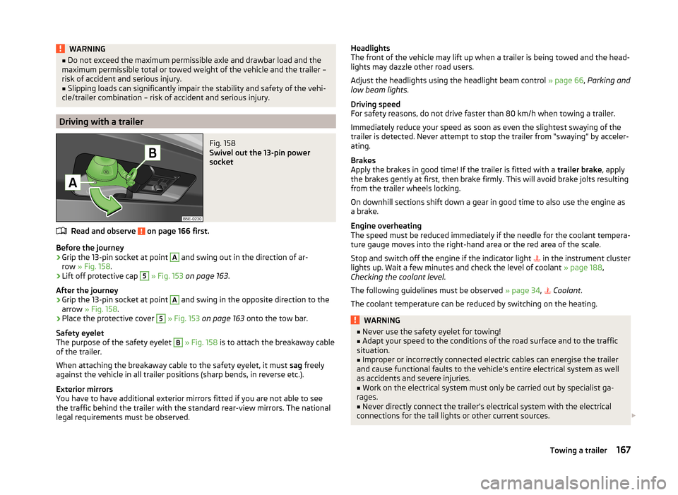
›
Grip the 13-pin socket at point
A
and swing out in the direction of ar-
row » Fig. 158 .
›
Lift off protective cap
5
» Fig. 153 on page 163 .
After the journey
›
Grip the 13-pin socket at point
A
and swing in the opposite direction to the
arrow » Fig. 158 .
›
Place the protective cover
5
» Fig. 153 on page 163 onto the tow bar.
Safety eyelet
The purpose of the safety eyelet
B
» Fig. 158 is to attach the breakaway cable
of the trailer.
When attaching the breakaway cable to the safety eyelet, it must sag freely
against the vehicle in all trailer positions (sharp bends, in reverse etc.).
Exterior mirrors
You have to have additional exterior mirrors fitted if you are not able to see
the traffic behind the trailer with the standard rear-view mirrors. The national
legal requirements must be observed.
Headlights
The front of the vehicle may lift up when a trailer is being towed and the head-
lights may dazzle other road users.
Adjust the headlights using the headlight beam control » page 66, Parking and
low beam lights .
Driving speed
For safety reasons, do not drive faster than 80 km/h when towing a trailer.
Immediately reduce your speed as soon as even the slightest swaying of the
trailer is detected. Never attempt to stop the trailer from “swaying” by acceler-
ating.
Brakes
Apply the brakes in good time! If the trailer is fitted with a trailer brake, apply
the brakes gently at first, then brake firmly. This will avoid brake jolts resulting
from the trailer wheels locking.
On downhill sections shift down a gear in good time to also use the engine as
a brake.
Engine overheating
The speed must be reduced immediately if the needle for the coolant tempera-
ture gauge moves into the right-hand area or the red area of the scale.
Stop and switch off the engine if the indicator light in the instrument cluster
lights up. Wait a few minutes and check the level of coolant » page 188,
Checking the coolant level .
The following guidelines must be observed » page 34,
Coolant
.
The coolant temperature can be reduced by switching on the heating.WARNING■ Never use the safety eyelet for towing!■Adapt your speed to the conditions of the road surface and to the traffic
situation.■
Improper or incorrectly connected electric cables can energise the trailer
and cause functional faults to the vehicle's entire electrical system as well
as accidents and severe injuries.
■
Work on the electrical system must only be carried out by specialist ga-
rages.
■
Never directly connect the trailer's electrical system with the electrical
connections for the tail lights or other current sources.
167Towing a trailer
Page 170 of 246
Note■After coupling the trailer and connecting the power socket, check that the
rear lights on the trailer are working correctly.■
If there is an error in the trailer lighting, check the fuses in the fuse box in
the dash panel » page 216.
■
Contact between the breakaway cable and the safety eyelet can result in
mechanical wear on the surface protection of the eyelet. Such wear does not
impair the functioning of the safety eyelet and does not constitute a fault. It is
excluded from the warranty coverage.
■
If you tow a trailer frequently, you should also have your vehicle inspected
between service intervals.
■
The handbrake on the towing vehicle must be applied when coupling and un-
coupling the trailer.
Trailer stabilisation (TSA)
Read and observe
on page 166 first.
The trailer stabilisation is an extension of the stabilisation control that works
in conjunction with the counter-steering assistance to reduce the amount the
trailer "sways".
After turning on the ignition, the ESC indicator light in the instrument clus-
ter lights up for about 2 seconds longer than the ABS indicator light.
Function requirements for trailer stabilisation. The coupling device was factory-fitted or purchased from the ŠKODA Origi-
nal Accessories.
The ESC is active. (Warning lights or
do
not illuminate in the instru-
ment cluster).
The trailer is electrically connected to the towing vehicle via the trailer
socket.
The speed is higher than approx. 60 km/h.
The trailer has a rigid drawbar.
WARNINGThe increased safety offered by the trailer stabilisation must not tempt you to take greater risks than otherwise.CAUTION■ The trailer stabilisation need not be able to correctly detect all of driving sit-
uations.■
Light trailers that sway are not always detected and therefore stabilised ac-
cordingly by the trailer stabilisation.
■
Release the pressure on the accelerator pedal if the system is being regula-
ted.
■
Avoid abrupt and sudden driving/braking manoeuvres.
Note
The trailer stabilisation works for both braked and unbraked trailers.
Anti-theft alarm system
Read and observe
on page 166 first.
When the vehicle is locked, the alarm is activated when the electrical connec-
tion to the trailer is interrupted.
Always switch off the anti-theft alarm system before a trailer is coupled or un-
coupled » page 54 .
Conditions for including a trailer in the anti-theft alarm system. The vehicle is factory-fitted with an anti-theft alarm system and towing
device.
The trailer is electrically connected to the towing vehicle via the trailer
socket.
The electrical system of the vehicle and trailer is functional.
The vehicle is locked with the vehicle key and the anti-theft alarm system
is activated.
Note
For technical reasons, trailers with rear LED lights cannot be connected to the
anti-theft alarm system.168Driving
Page 188 of 246
Specifications and capacity (in l) for vehicles with fixed service intervalsPetrol enginesSpecificationCapacity1.4 ltr./92 kW TSIVW 501 01, VW 502 003.6
1.8 l/112, 118 kW TSI
VW 502 00
4.6
applies to RussiaSAE 0W - 30
VW 502 00/505 00
2.0 ltr./147 kW TSI
VW 502 00
4.6
applies to Russia SAE 0W - 30
VW 502 00/505 003.6 l/191 kW FSIVW 502 005.5Diesel engines a)SpecificationCapacity1.6 ltr./77 kW TDI CRVW 507 004.32.0 ltr/103 kW TDI CR DPFVW 507 004.32.0 ltr/125 kW TDI CR DPFVW 507 004.3a)
Engine oil VW 505 01 can optionally be used in diesel engines
without a DPF.
CAUTION
■
If the above engine oils are not available, a different engine oil can be used in
an emergency. To prevent damage to the engine, a maximum of 0.5 litres only
of the following engine oils may be used until the next oil change: ■ For petrol engine models: ACEA A3/ACEA B4 or API SN/API SM;
■ For diesel engine models: ACEA C3 or API CJ-4.
Checking the oil level
Fig. 163
Principle sketch: Dipstick
Read and observe and on page 185 first.
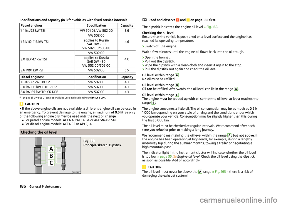
The dipstick indicates the engine oil level » Fig. 163.
Checking the oil level
Ensure that the vehicle is positioned on a level surface and the engine has
reached its operating temperature.
›
Switch off the engine.
Wait a few minutes until the engine oil flows back into the oil trough.
›
Open the bonnet.
›
Pull out the dipstick.
›
Wipe the dipstick with a clean cloth and insert it again to the stop.
›
Pull the dipstick out again and check the oil level.
Oil level within range
A
No oil must be refilled.
Oil level within range
B
Oil can be refilled. Afterwards, the oil level can lie in the range
A
.
Oil level within range
C
The engine must be topped up with oil so that the oil level at least reaches the
range
B
.
The engine consumes a little oil. The oil consumption may be as much as 0.5 l/
1 000 km depending on your style of driving and the conditions under which
you operate your vehicle. Consumption may be slightly higher than this during
the first 5 000 km.
The oil level must be checked at regular intervals. We recommend after each
time you refuel or prior to making a long journey.
We recommend maintaining the oil level within the range
A
, but not above , if
the engine has been operating at high loads, for example, during a lengthy
motorway trip during the summer months, towing a trailer or negotiating a
high mountain pass.
The indicator light in the instrument cluster will indicate whether the oil level
is too low » page 35,
Engine oil level
. Check the oil level using the dipstick
as soon as possible. Add oil accordingly.
CAUTION
The oil level must never be above the A range » Fig. 163 – there is a risk of
damaging the exhaust system!186General Maintenance
Page 199 of 246
›Switch on the ignition.›Press the
» Fig. 170 symbol button for longer than 2 seconds.
If the warning light
in the instrument cluster lights up and does not go out
after the system configuration, this indicates a system fault.
If the warning light
in the instrument cluster flashes, there is a system fault.
Tyre pressure indicator
The warning light
in the instrument cluster lights up when any of the fol-
lowing conditions are met.
› The tyre inflation pressure is low.
› The structure of the tyre is damaged.
› The vehicle is loaded on one side.
› The wheels of one axle are loaded more heavily (e.g. when towing a trailer or
when driving uphill or downhill).
› Snow chains are mounted.
› The spare wheel is mounted.
› One wheel per axle was changed.WARNING■
When the warning light in the instrument cluster lights up, immediate-
ly reduce the speed and avoid sudden steering and brake manoeuvres.
Stop the vehicle as soon as possible and inspect the tyres and their infla-
tion pressure.■
Under certain circumstances (e.g. sporty style of driving, wintry or un-
paved roads) the warning light
in the instrument cluster can be delayed
or does not light up at all.
CAUTION
■ The system cannot warn in case of very rapid tyre inflation pressure loss, e.g.
in case of sudden tyre damage. In this case carefully bring the vehicle to a
standstill without sudden steering movements or sharp braking.■
To ensure a proper functioning of the tyre control display, it is necessary to
repeat the basic setting every 10000 km or once a year.
■
The tyre pressure monitor does not replace the need to check tyre pressure
regularly.
Spare and temporary spare wheelFig. 171
Fixing the spare or temporary
spare wheel
Read and observe and on page 193 first.
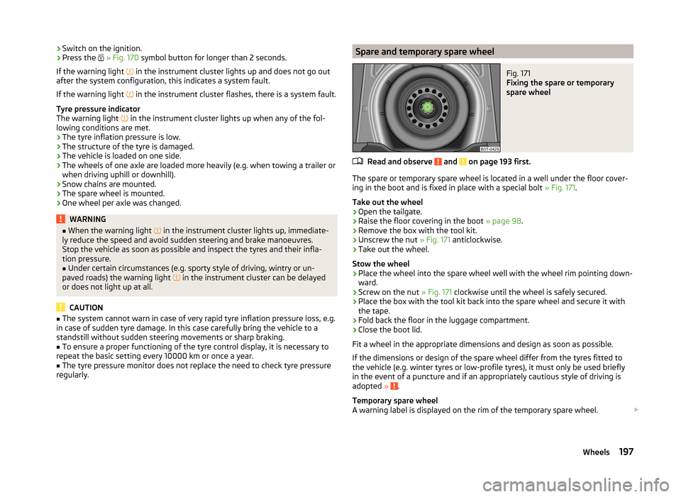
The spare or temporary spare wheel is located in a well under the floor cover-
ing in the boot and is fixed in place with a special bolt » Fig. 171.
Take out the wheel
›
Open the tailgate.
›
Raise the floor covering in the boot » page 98.
›
Remove the box with the tool kit.
›
Unscrew the nut » Fig. 171 anticlockwise.
›
Take out the wheel.
Stow the wheel
›
Place the wheel into the spare wheel well with the wheel rim pointing down-
ward.
›
Screw on the nut » Fig. 171 clockwise until the wheel is safely secured.
›
Place the box with the tool kit back into the spare wheel and secure it with
the tape.
›
Fold back the floor in the luggage compartment.
›
Close the boot lid.
Fit a wheel in the appropriate dimensions and design as soon as possible.
If the dimensions or design of the spare wheel differ from the tyres fitted to
the vehicle (e.g. winter tyres or low-profile tyres), it must only be used briefly
in the event of a puncture and if an appropriately cautious style of driving is
adopted »
.
Temporary spare wheel
A warning label is displayed on the rim of the temporary spare wheel.
197Wheels
Page 202 of 246

Do-it-yourself
Emergency equipment and self-help
Emergency equipment
Introduction
This chapter contains information on the following subjects:
First aid kit and warning triangle
200
fire extinguisher
200
Vehicle tool kit
201
First aid kit and warning triangle
Fig. 173
Stowage compartment for the first aid kit: Superb / Superb Com-
bi
Fig. 174
Placing of the warning triangle
First-aid box
The compartment for stowing the first-aid box is located in the right of the
boot » Fig. 173 .
Warning triangle
The warning triangle can be attached to the rear wall trim panel with rubber
straps » Fig. 174 .WARNINGThe first-aid kit and warning triangle must always be secured safely so that
they do not come loose when making an emergency braking or in a vehicle
collision which could cause injuries to occupants.
Note
■ Pay attention to the expiration date of the first-aid kit.■We recommend using a first-aid kit from ŠKODA Original Accessories, which
are available from a ŠKODA Partner.
fire extinguisher
Fig. 175
Fire extinguisher
The fire extinguisher is attached by two straps in a holder under the driver
seat.
Removing / attaching
›
Loosen the two straps by pulling the buckles in the direction of the ar-
row » Fig. 175 .
›
Remove the fire extinguisher.
Installation is carried out in the reverse order.
Please read carefully the instructions which are attached to the fire extin- guisher.
200Do-it-yourself
Page 203 of 246
The fire extinguisher must be checked by an authorised person once a year.
The national legal requirements must be observed.WARNINGThe fire extinguisher must always be secured safely so that they do not
come loose when making an emergency braking or in a vehicle collision
which could cause injuries to occupants.
Note
■ The fire extinguisher must comply with national legal requirements.■Pay attention to the expiration date of the fire extinguisher. Proper function-
ing of the fire extinguisher is not assured once it has passed its expiry date.■
The fire extinguisher is part of the scope of delivery in certain countries only.
Vehicle tool kit
Fig. 176
Vehicle tool kit
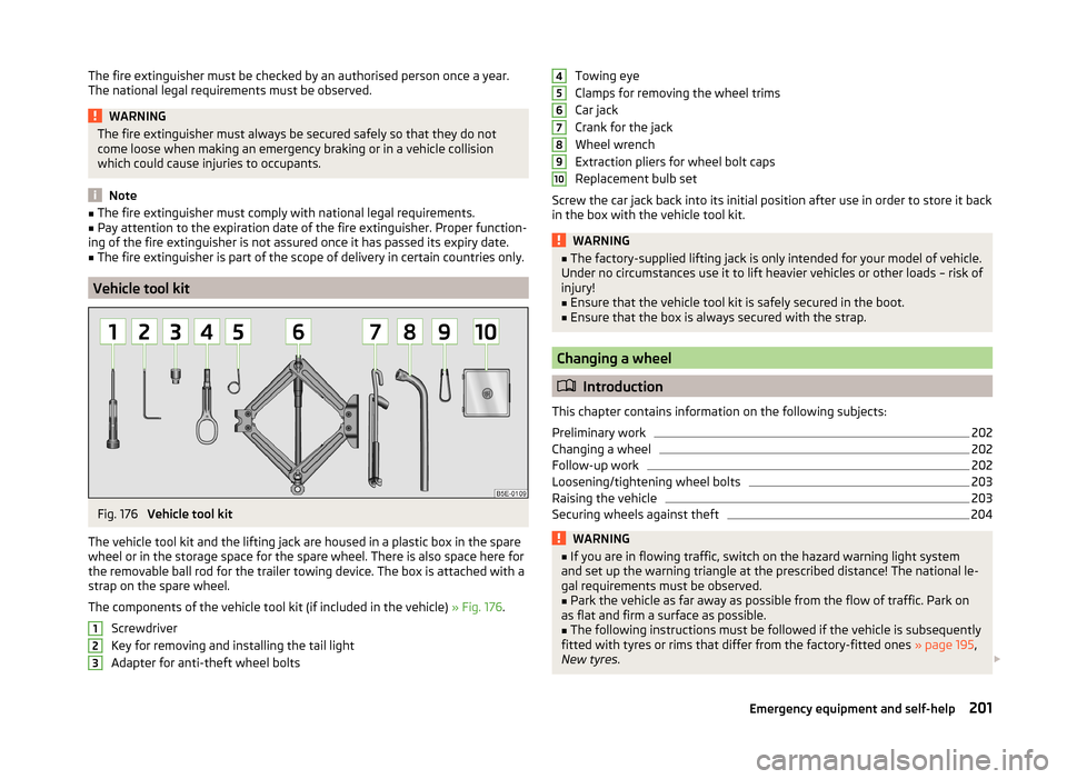
The vehicle tool kit and the lifting jack are housed in a plastic box in the spare
wheel or in the storage space for the spare wheel. There is also space here for
the removable ball rod for the trailer towing device. The box is attached with a
strap on the spare wheel.
The components of the vehicle tool kit (if included in the vehicle) » Fig. 176.
Screwdriver
Key for removing and installing the tail light
Adapter for anti-theft wheel bolts
123Towing eye
Clamps for removing the wheel trims
Car jack
Crank for the jack
Wheel wrench
Extraction pliers for wheel bolt caps
Replacement bulb set
Screw the car jack back into its initial position after use in order to store it back
in the box with the vehicle tool kit.WARNING■ The factory-supplied lifting jack is only intended for your model of vehicle.
Under no circumstances use it to lift heavier vehicles or other loads – risk of
injury!■
Ensure that the vehicle tool kit is safely secured in the boot.
■
Ensure that the box is always secured with the strap.
Changing a wheel
Introduction
This chapter contains information on the following subjects:
Preliminary work
202
Changing a wheel
202
Follow-up work
202
Loosening/tightening wheel bolts
203
Raising the vehicle
203
Securing wheels against theft
204WARNING■ If you are in flowing traffic, switch on the hazard warning light system
and set up the warning triangle at the prescribed distance! The national le-
gal requirements must be observed.■
Park the vehicle as far away as possible from the flow of traffic. Park on
as flat and firm a surface as possible.
■
The following instructions must be followed if the vehicle is subsequently
fitted with tyres or rims that differ from the factory-fitted ones » page 195,
New tyres .
45678910201Emergency equipment and self-help
Page 210 of 246
Negative cable - colour coding in the majority of cases is black.
Jump-starting in vehicles with the START-STOP system
Fig. 183
Engine earth: START-STOP sys-
tem
Read and observe and on page 207 first.
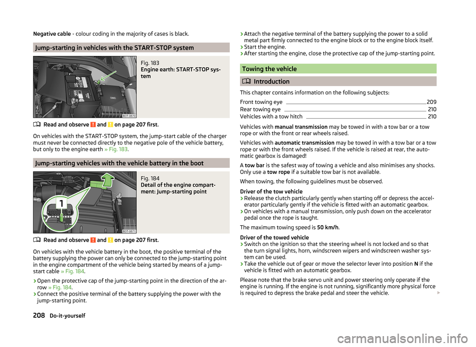
On vehicles with the START-STOP system, the jump-start cable of the charger
must never be connected directly to the negative pole of the vehicle battery,
but only to the engine earth » Fig. 183.
Jump-starting vehicles with the vehicle battery in the boot
Fig. 184
Detail of the engine compart-
ment: Jump-starting point
Read and observe and on page 207 first.
On vehicles with the vehicle battery in the boot, the positive terminal of the
battery supplying the power can only be connected to the jump-starting point
in the engine compartment of the vehicle being started by means of a jump-
start cable » Fig. 184.
›
Open the protective cap of the jump-starting point in the direction of the ar-
row » Fig. 184 .
›
Connect the positive terminal of the battery supplying the power with the
jump-starting point.
› Attach the negative terminal of the battery supplying the power to a solid
metal part firmly connected to the engine block or to the engine block itself.›
Start the engine.
›
After starting the engine, close the protective cap of the jump-starting point.
Towing the vehicle
Introduction
This chapter contains information on the following subjects:
Front towing eye
209
Rear towing eye
210
Vehicles with a tow hitch
210
Vehicles with manual transmission may be towed in with a tow bar or a tow
rope or with the front or rear wheels raised.
Vehicles with automatic transmission may be towed in with a tow bar or a tow
rope or with the front wheels raised. If the vehicle is raised at rear, the auto-
matic gearbox is damaged!
A tow bar is the safest way of towing a vehicle and also minimises any shocks.
Only use a tow rope if a suitable tow bar is not available.
When towing, the following guidelines must be observed.
Driver of the tow vehicle
›
Release the clutch particularly gently when starting off or depress the accel-
erator particularly gently if the vehicle is fitted with an automatic gearbox.
›
On vehicles with a manual transmission, only push down on the accelerator
pedal once the rope is taught.
The maximum towing speed is 50 km/h.
Driver of the towed vehicle
›
Switch on the ignition so that the steering wheel is not locked and so that
the turn signal lights, horn, windscreen wipers and windscreen washer sys-
tem can be used.
›
Take the vehicle out of gear or move the selector lever into position N if the
vehicle is fitted with an automatic gearbox.
Please note that the brake servo unit and power steering only operate if the
engine is running. If the engine is not running, significantly more physical force
is required to depress the brake pedal and steer the vehicle.
208Do-it-yourself
Page 211 of 246
If using a tow rope, ensure that it is always kept taught.
CAUTION
■Do not tow start the engine – there is a risk of damaging the engine and the
catalytic converter. The battery from another vehicle can be used as a jump-
start aid » page 207 , Jump-starting .■
If the gearbox no longer contains any oil because of a defect, your vehicle
must only be towed with the driven wheels raised clear of the ground or on a
special breakdown vehicle or trailer.
■
The vehicle must be transported on a special breakdown vehicle or trailer if it
is not possible to tow in the vehicle in the way described or if the towing dis-
tance is greater than 50 km.
■
To protect both vehicles when tow-starting or towing, the tow rope should
be elastic. Thus one should only use plastic fibre rope or a rope made out of a
similarly elastic material.
■
While towing, take care to avoid impermissibly high tensile forces or jerky
loads. There is always a risk of excessive stresses and damage resulting at the
points to which you attach the tow rope or tow bar when you attempt to tow a
vehicle which is not standing on a paved road.
■
Attach the tow rope or the tow bar to the towing eyes » page 209 , Front
towing eye or » page 210 , Rear towing eye to the detachable ball head of the
towing equipment » page 163 .
Note
■
We recommend using a tow rope from ŠKODA Original Accessories, which is
available from a ŠKODA Partner.■
Towing another vehicle requires a certain amount of practice. Both drivers
should be familiar with the particular points about towing a vehicle. Unskilled
drivers should not attempt to tow in another vehicle or to be towed in.
■
When towing, respect the national legal provisions, especially those which
relate to the identification of the towing vehicle and the vehicle being towed.
■
The tow rope must not be twisted as it may in certain circumstances result in
the front towing eye being unscrewed out of your vehicle.
Front towing eyeFig. 185
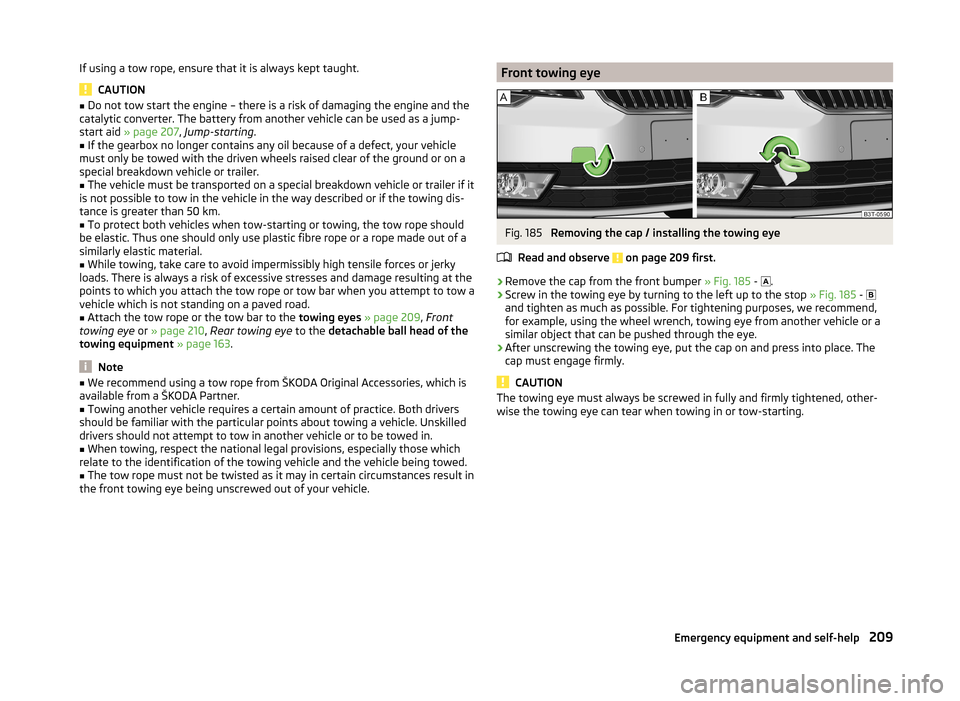
Removing the cap / installing the towing eye
Read and observe
on page 209 first.
›
Remove the cap from the front bumper » Fig. 185 -
.
›
Screw in the towing eye by turning to the left up to the stop
» Fig. 185 -
and tighten as much as possible. For tightening purposes, we recommend,
for example, using the wheel wrench, towing eye from another vehicle or a
similar object that can be pushed through the eye.
›
After unscrewing the towing eye, put the cap on and press into place. The
cap must engage firmly.
CAUTION
The towing eye must always be screwed in fully and firmly tightened, other-
wise the towing eye can tear when towing in or tow-starting.209Emergency equipment and self-help
Page 212 of 246
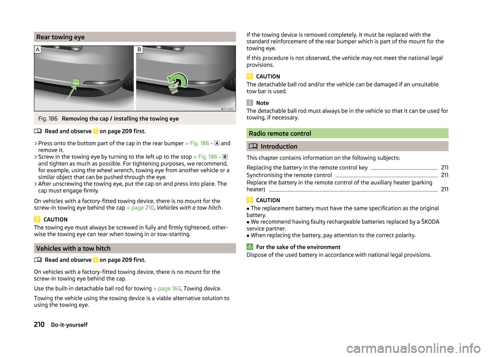
Rear towing eyeFig. 186
Removing the cap / installing the towing eye
Read and observe
on page 209 first.
›
Press onto the bottom part of the cap in the rear bumper » Fig. 186 -
and
remove it.
›
Screw in the towing eye by turning to the left up to the stop » Fig. 186 -
and tighten as much as possible. For tightening purposes, we recommend,
for example, using the wheel wrench, towing eye from another vehicle or a
similar object that can be pushed through the eye.
›
After unscrewing the towing eye, put the cap on and press into place. The
cap must engage firmly.
On vehicles with a factory-fitted towing device, there is no mount for the
screw-in towing eye behind the cap » page 210, Vehicles with a tow hitch .
CAUTION
The towing eye must always be screwed in fully and firmly tightened, other-
wise the towing eye can tear when towing in or tow-starting.
Vehicles with a tow hitch
Read and observe
on page 209 first.
On vehicles with a factory-fitted towing device, there is no mount for the
screw-in towing eye behind the cap.
Use the built-in detachable ball rod for towing » page 163, Towing device .
Towing the vehicle using the towing device is a viable alternative solution to
using the towing eye.
If the towing device is removed completely, it must be replaced with the
standard reinforcement of the rear bumper which is part of the mount for the
towing eye.
If this procedure is not observed, the vehicle may not meet the national legal
provisions.
CAUTION
The detachable ball rod and/or the vehicle can be damaged if an unsuitable
tow bar is used.
Note
The detachable ball rod must always be in the vehicle so that it can be used for
towing, if necessary.
Radio remote control
Introduction
This chapter contains information on the following subjects:
Replacing the battery in the remote control key
211
Synchronising the remote control
211
Replace the battery in the remote control of the auxiliary heater (parking
heater)
211
CAUTION
■ The replacement battery must have the same specification as the original
battery.■
We recommend having faulty rechargeable batteries replaced by a ŠKODA
service partner.
■
When replacing the battery, pay attention to the correct polarity.
For the sake of the environment
Dispose of the used battery in accordance with national legal provisions.210Do-it-yourself