towing SKODA SUPERB 2014 2.G / (B6/3T) Owner's Manual
[x] Cancel search | Manufacturer: SKODA, Model Year: 2014, Model line: SUPERB, Model: SKODA SUPERB 2014 2.G / (B6/3T)Pages: 246, PDF Size: 17.16 MB
Page 5 of 246
Table of Contents
Abbreviations
Safety
Passive Safety
6
General information
6
Correct and safe seated position
7
Seat belts
10
Using seat belts
10
Inertia reels and belt tensioners
13
Airbag system
14
Description of the airbag system
14
Airbag overview
15
Deactivating airbags
19
Transporting children safely
21
Child seat
21
Fastening systems
23
Operation
Cockpit
27
Overview
26
Instruments and Indicator Lights
28
Instrument cluster
28
Warning lights
32
Information system
39
Driver information system
39
Multifunction display (MFD)
41
MAXI DOT display
44
Service interval display
46
Unlocking and opening
48
Unlocking and locking
48
Anti-theft alarm system
54
Luggage compartment lid
55Electric boot lid (Superb Combi)57Electric power windows59
Electric sliding/tilting roof
62
Panoramic sliding/tilting roof (Superb Estate)
63
Lights and visibility
65
Lights
65
Interior lights
71
Visibility
73
Windscreen wipers and washers
75
Rear mirror
77
Seats and useful equipment
79
Adjusting the seats
79
Seat features
83
Practical equipment
86
Luggage compartment
95
Removable light (Superb Combi)
101
Variable loading floor in the luggage
compartment (Estate)
102
Extending variable loading floor with
integrated aluminium rails and faseting
elements (Superb Combi)
103
Net partition (Superb Combi)
105
Roof rack system
106
Air conditioning system
108
Heating, ventilation, cooling
108
Air conditioning system (manual air
conditioning system)
110
Climatronic (automatic air conditioning
system)
113
Auxiliary heating (auxiliary heating and
ventilation)
116
Communication and multimedia
119
General information
119
Universal telephone preinstallation GSM II
122
Universal telephone preinstallation GSM IIl
124
WLAN
127Voice control129Multimedia131
Driving
Starting-off and Driving
135
Starting and stopping the engine using the key
135
Starting and stopping the engine - KESSY
137
Brakes
140
Manual gear changing and pedals
141
Automatic gearbox
142
Running in
145
Economical driving and environmental
sustainability
146
Avoiding damage to your vehicle
149
Driving abroad
150
Assist systems
151
Brake assist systems
151
Parking aid
153
Park assist
154
Cruise Control System
158
START-STOP
159
Fatigue detection (break recommendation)
162
Towing a trailer
163
Towing device
163
Trailer
166
General Maintenance
Car care
169
Services, modifications, and technical
alterations
169
Washing your car
172
Taking care of your vehicle exterior
173
Taking care of the interior
1763Table of Contents
Page 6 of 246
Inspecting and replenishing179Fuel179
Engine compartment
182
Engine oil
185
Coolant
187
Brake fluid
189
Vehicle battery
189
Wheels
193
Tyres and wheel rims
193
Winter operation
198
Do-it-yourself
Emergency equipment and self-help
200
Emergency equipment
200
Changing a wheel
201
Tyre repair
204
Jump-starting
207
Towing the vehicle
208
Radio remote control
210
Emergency unlocking/locking
212
Emergency operation of the sliding/tilting
roof
213
Replacing windscreen wiper blades
214
Fuses and light bulbs
215
Fuses
215
Bulbs
219
Technical data
Technical data
224
Vehicle data
224
Index
4Table of Contents
Page 53 of 246
Information messageRead and observe
on page 48 first.
Key in the vehicle
The protection against inadvertently locking the key in the vehicle unlocks the
vehicle automatically if the following conditions are met.
The vehicle, including the boot lit, has been locked.
The key with which the vehicle has been locked remains in the vehicle in
the zone
D
» Fig. 32 on page 50 .
The turn signal lights flash four times as confirmation that the vehicle has
been unlocked again.
The following message is shown in the information cluster display. Key in vehicle.
KEY IN VEHICLE
Additionally, on vehicles which are fitted with the anti-theft alarm system, an audible signal sounds.
The system has not found a key
If the system has not found a key in the vehicle, the following message ap-
pears in the display of the instrument cluster.
Key not found.
NO KEY
This can occur if the key is outside the vehicle, the battery in the key is dis-
charged, the key is defective or the electromagnetic field is strongly disturbed.
Fault in KESSY system
If there is a fault in the KESSY system, the following message will appear in
the display of the instrument cluster.
Keyless access system faulty.
CHECK KEYLESS
Low voltage of the key battery
If the voltage of the battery in the remote control key is too low, the following
message appears in the display of the instrument cluster.
Change the key battery!
KEY BATTERY
Change the key battery » page 211!
Parking the vehicle
Read and observe
on page 48 first.
If the vehicle is not unlocked within 60 or 90 hours, the sensors in the handle
of the driver or front passenger's door are deactivated automatically » Fig. 32
on page 50 .
Activation after 60 hours
›
Unlock the driver's door using the sensor
2
» Fig. 32 on page 50 .
›
Press the handle of the boot lid.
›
Unlock the vehicle using the symbol button
on the remote control key.
›
Unlocking the driver's door in an emergency » page 212.
Activation after 90 hours
›
Unlock the vehicle using the symbol button on the remote control key.
›
Unlocking the driver's door in an emergency
» page 212.
Safe securing
Read and observe
on page 48 first.
The door locks are blocked automatically if the vehicle is locked from the out-side. Afterwards, it is not possible to open the doors with the door handle ei-
ther from the inside or from the outside.
This fact is pointed out by the following message on the display of the instru-
ment cluster after switching out the ignition.
Check SAFELOCK! Log book!
CHECK SAFELOCK
Switching off
The safe lock can be switched off in one of the following ways.
›
By locking twice within 2 seconds.
›
By disabling the interior monitoring » page 54, Interior monitor and towing
protection .
If the vehicle is locked and the safe securing system is switched off, the door can be opened separately from the inside by a single pull on opening lever.
Switching on
The safelock switches on automatically the next time the vehicle is locked and
unlocked.
51Unlocking and opening
Page 56 of 246
Anti-theft alarm system
Introduction
This chapter contains information on the following subjects:
Activating/deactivating
54
Interior monitor and towing protection
54
The anti-theft alarm system (hereinafter referred to only as alarm system) in-
creases protection against break-in attempts into the vehicle.
The alarm system triggers audible and visual signals if an attempt is made to
break into the vehicle (hereafter referred to only as alarm).
An alarm is triggered when the following monitored areas of the vehicle have a fault.
› Bonnet.
› Boot lid.
› Doors.
› Ignition lock.
› Vehicle inclination
» page 54.
› Interior of car
» page 54.
› A drop in voltage of the on-board power supply.
› Socket of the factory-fitted towing device
» page 163, Towing a trailer .
An alarm is immediately triggered if either of the two battery terminals is dis-
connected while the anti-theft alarm system is activated.
The alarm is switched off by unlocking the vehicle or switching on the ignition.
CAUTION
Before leaving the vehicle, it must be checked that all of the windows, doors
and the sliding/tilting roof are locked in order to ensure the full functionality of
the anti-theft alarm system.
Note
The working life of the alarm siren is 5 years.Activating/deactivating
Read and observe
on page 54 first.
Activating
The anti-theft alarm system is activated automatically approximately 30 sec-
onds after the vehicle is locked.
If you unlock the vehicle and do not open a door or the boot lid within the next
30 seconds, the vehicle will lock again automatically and the safelock system
or anti-theft alarm system will be switched on. This function is intended to
prevent the car being unlocked unintentionally.
Deactivating
The anti-theft alarm system is deactivated automatically after the vehicle is
unlocked. If the vehicle is not opened within 30 seconds, the anti-theft alarm
system is automatically activated again.
The alarm system is also deactivated if you unlock the driver door using the
key within 45 seconds of locking the vehicle.
Note
■ If the car is unlocked with the key in the driver door, insert the key into the
ignition and switch the ignition to deactivate the alarm system.■
You can switch the audible signalling of the activation of the warning system
on and off in the Maxi DOT display in the menu item ATA confirm » page 45 .
Interior monitor and towing protection
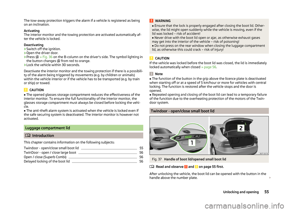
Fig. 36
Button for interior monitor and
towing protection
Read and observe on page 54 first.
The interior monitor detects movements inside the car and then triggers the
alarm.
54Operation
Page 57 of 246
The tow-away protection triggers the alarm if a vehicle is registered as being
on an inclination.
Activating
The interior monitor and the towing protection are activated automatically af-
ter the vehicle is locked.
Deactivating›
Switch off the ignition.
›
Open the driver door.
›
Press
» Fig. 36 on the B-column on the driver's side. The symbol lighting in
the button changes
from red to orange.
›
Lock the vehicle within 30 seconds.
Deactivate the interior monitor and the towing protection if there is a possibili-
ty of the alarm being triggered by movements (e.g. by children or animals)
within the vehicle interior or if the vehicle has to be transported (e.g. by train
or ship) or towed.
CAUTION
■ The opened glasses storage compartment reduces the effectiveness of the
interior monitor. To ensure the full functionality of the interior monitor, the
glasses storage compartment must always be closed before locking the vehi-
cle.■
The anti-theft alarm system is activated when the vehicle is locked even if
the safe securing system is deactivated. The interior monitor is however not
activated.
Luggage compartment lid
Introduction
This chapter contains information on the following subjects:
Twindoor - open/close small boot lid
55
TwinDoor - open / close large boot
56
Open / close (Superb Combi)
56
Delayed locking of the boot lid
56WARNING■ Ensure that the lock is properly engaged after closing the boot lid. Other-
wise, the lid might open suddenly while the vehicle is moving, even if the
lid was locked – risk of accident!■
Never drive with the boot lid open or ajar, as otherwise exhaust gases
may get into the interior of the vehicle – risk of poisoning!
■
Do not press on the rear window when closing the luggage compartment
lid, as otherwise this could crack – risk of injury!
CAUTION
If the vehicle was locked before the boot lid was closed, the lid is immediately
locked automatically when closed » page 56.
Note
■
The function of the button in the grip above the licence plate is deactivated
when starting off or at a speed of 5 km/hour or more for vehicles with central
locking. The function is restored after the vehicle stops and the door is
opened.■
Repeated opening and closing of the boot lid can lead to a temporary failure
of the function due to the overheating protection of the motors of the Twin-
door system.
Twindoor - open/close small boot lid
Fig. 37
Handle of boot lid/opened small boot lid
Read and observe
and on page 55 first.
After unlocking the vehicle, the boot lid can be opened with the button in the
handle above the number plate.
55Unlocking and opening
Page 72 of 246
The rear fog light is switched off in the reverse order.
The warning light
lights up in the instrument cluster when the rear fog light
is switched on » page 32.
When in reverse gear only the rear fog lamp illuminates on the driver's side.
Only the rear fog light on the trailer lights up if the vehicle has a factory-fitted
towing device or a towing device from ŠKODA original accessories and it is
driven with a trailer.
COMING HOME / LEAVING HOME
Read and observe
on page 65 first.
COMING HOME/LEAVING HOME (hereafter referred to only as function)
switches on the lights for a short time after leaving the vehicle or when ap-
proaching the vehicle.
The daytime running lights are switched on automatically if the following
conditions are met:
The light switch is in the position » Fig. 50
on page 68 .
The visibility in the vehicle environment is reduced.
The ignition is switched off.
The parking aid is activated.
The function switches on the following light, depending on the equipment
fitted.
› Parking lights
› Low beam
› Entry lighting in the exterior mirrors
› Licence plate light
The light is controlled on the basis of information that is collected from the
holder mounted in the rear-view mirror sensor » page 68 .
COMING HOME
The light turns on automatically when you open the driver's door on (within 60
seconds of turning off the ignition).
The light turns off 10 seconds after closing all the doors and the boot lid or af-
ter the pre-set time has expired.
If a door or the boot lid remains open, the light goes out after 60 seconds.
LEAVING HOME
The light turns on automatically after the vehicle is unlocked with the remote
control.
The light turns off after 10 seconds or after a pre-set time or after the vehicle
is locked.
Activate/deactivate the function
The functions and settings of the illumination time can be activated/deactiva- ted via the MAXI DOT display in the menu items Coming Home or Leaving
Home » page 45 .
CAUTION
■
Do not attach any stickers or similar objects in front of the light sensor on
the windscreen to avoid impairing the function or its reliability.■
If this function is activated constantly, the battery will be heavily discharged
particularly in short-haul traffic.
Hazard warning light system
Fig. 52
Button for hazard warning light
system
Read and observe on page 65 first.
Switching on/off
›
Press the
» Fig. 52 button.
All the turn signal lights on the vehicle flash at the same time when the hazard
warning light system is switched on. The warning light for the turn signals and
the warning light in the button also flash at the same time. The hazard warn-
ing light system can also be operated if the ignition is switched off.
If one of the airbags is deployed, the hazard warning light system will switch
on automatically.
70Operation
Page 105 of 246
WARNINGEnsure that the carrier rails and variable loading floor are correctly fastened
when installing the variable loading floor. If this is not the case, there is a
risk of injury for the occupants.
Extending variable loading floor with integrated aluminium rails
and faseting elements (Superb Combi)
Introduction
This chapter contains information on the following subjects:
Partial extension of variable load floor
103
Divide boot
103
Fit and remove variable loading floor
104
Fixing set
104
Movable lashing eyes
105
The variable loading floor makes handling of bulky items of luggage easier.
CAUTION
The maximum permissible load of the variable loading floor is 75 kg.
Note
The space below the variable loading floor can be used for stowing objects, for
example the fastening elements, removed foldable boot cover, etc.
Partial extension of variable load floor
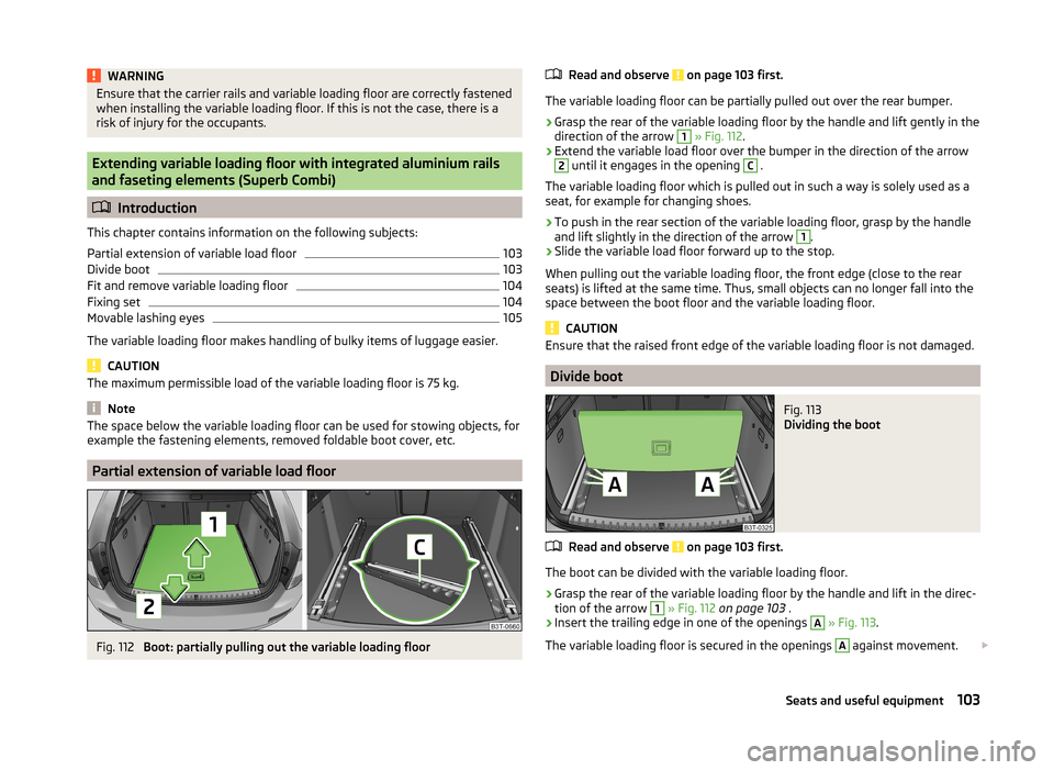
Fig. 112
Boot: partially pulling out the variable loading floor
Read and observe on page 103 first.
The variable loading floor can be partially pulled out over the rear bumper.
›
Grasp the rear of the variable loading floor by the handle and lift gently in the
direction of the arrow
1
» Fig. 112 .
›
Extend the variable load floor over the bumper in the direction of the arrow
2
until it engages in the opening
C
.
The variable loading floor which is pulled out in such a way is solely used as a
seat, for example for changing shoes.
›
To push in the rear section of the variable loading floor, grasp by the handle
and lift slightly in the direction of the arrow
1
.
›
Slide the variable load floor forward up to the stop.
When pulling out the variable loading floor, the front edge (close to the rear
seats) is lifted at the same time. Thus, small objects can no longer fall into the
space between the boot floor and the variable loading floor.
CAUTION
Ensure that the raised front edge of the variable loading floor is not damaged.
Divide boot
Fig. 113
Dividing the boot
Read and observe on page 103 first.
The boot can be divided with the variable loading floor.
›
Grasp the rear of the variable loading floor by the handle and lift in the direc-
tion of the arrow
1
» Fig. 112 on page 103 .
›
Insert the trailing edge in one of the openings
A
» Fig. 113 .
The variable loading floor is secured in the openings
A
against movement.
103Seats and useful equipment
Page 156 of 246
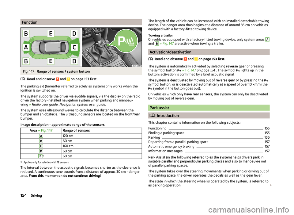
FunctionFig. 147
Range of sensors / system button
Read and observe
and on page 153 first.
The parking aid (hereafter referred to solely as system) only works when the
ignition is switched on.
The system supports the driver via audible signals, via the display on the radio
or via the factory-installed navigation system when parking and manoeu-
vring » Radio user guide, Navigation system user guide.
The system uses ultrasound waves to calculate the distance between the
bumper and an obstacle. The ultrasound sensors are located on the front/rear
bumper.
Image description - approximate range of the sensors
Area » Fig. 147Range of sensorsA120 cmB60 cmC160 cmD60 cmEa)60 cma)
Applies only for vehicles with 12 sensors.
The interval between the acoustic signals becomes shorter as the clearance is
reduced. A continuous tone sounds from a distance of approx. 30 cm - danger
area. From this moment on do not continue driving!
The length of the vehicle can be increased with an installed detachable towing
device. The danger area thus begins at a distance of around 35 cm on vehicles equipped with a factory-fitted towing device.
Towing a trailer
On vehicles equipped with a factory-fitted towing device, only system areas A
and
B
» Fig. 147 are active when towing a trailer.
Activation/deactivation
Read and observe
and on page 153 first.
The system is automatically activated by selecting reverse gear or pressing
the symbol button
» Fig. 147 on page 154 . The symbol
lights up in the
button; activation is confirmed by a brief acoustic signal.
The system is deactivated by moving out of reverse gear or by pressing the
symbol button, or is deactivated automatically at a speed of over 10 km/h (the
symbol in the button goes out).
On vehicles which only have rear sensors , the system can only be deactivated
by moving out of reverse gear.
Park assist
Introduction
This chapter contains information on the following subjects:
Functioning
155
Finding a parking space
155
Parking
156
Departing from a parallel parking space
157
Automatic emergency braking
157
Information messages
157
Park Assist (in the following referred to as the system) helps drivers park in
suitable parallel and perpendicular parking places and also to manoeuvre out
of parallel parking spaces.
The system takes over the steering movements when parking or driving out of
the parking space, the driver operates the pedals as well as the gear lever.
The state in which the steering wheel is operated by the system, is referred to
as parking operation.
154Driving
Page 165 of 246
Towing a trailer
Towing device
Introduction
This chapter contains information on the following subjects:
Description
163
Adjusting the ready position
164
Fitting the ball head
164
Check proper fitting
165
Removing the ball head
165
Use and care
166
If your vehicle has already been factory-fitted with a towing device or is fitted
with a towing device from ŠKODA Original Accessories, then it meets all of the
technical requirements and national legal regulations for towing a trailer.
Your vehicle is fitted with a 13-pin power socket for the electrical connection
between the vehicle and trailer. If the trailer that is to be towed has a 7-pin
connector , you can use a suitable adapter from ŠKODA Original Accessories.
The maximum trailer drawbar load is 80 kg.
WARNING■
Check that the tow bar is seated correctly and is secured in the mounting
recess before the start of every journey.■
Do not use the tow bar if it is not correctly inserted and secured in the
mounting recess.
■
Do not use the towing device if it is damaged or if there are parts missing.
■
Do not modify or adapt the towing device in any way.
■
Never release the tow bar while the trailer is still coupled.
CAUTION
Take care when handling the tow bar so as to avoid damaging the paintwork
on the bumper.DescriptionFig. 153
Carrier for the towing device/tow bar
Read and observe
and on page 163 first.
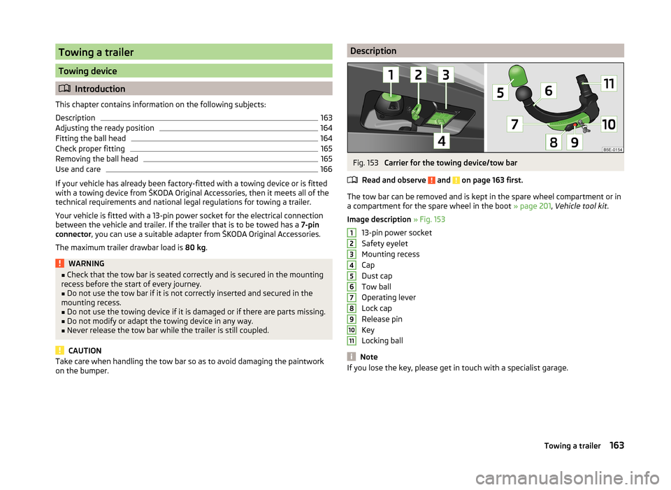
The tow bar can be removed and is kept in the spare wheel compartment or in
a compartment for the spare wheel in the boot » page 201, Vehicle tool kit .
Image description » Fig. 153
13-pin power socket
Safety eyelet
Mounting recess
Cap
Dust cap
Tow ball
Operating lever
Lock cap
Release pin
Key
Locking ball
Note
If you lose the key, please get in touch with a specialist garage.1234567891011163Towing a trailer
Page 167 of 246
CAUTION■After removing the key, always replace the cap on the lock of the operating
lever – risk of dirt getting into the lock.■
Keep the mounting recess of the towing equipment clean at all times. Such
dirt prevents the ball head from being attached securely.
■
After removing the ball head, always place the cap on the mounting recess.
Check proper fitting
Fig. 156
Check that the tow bar is attach-
ed properly
Read and observe and on page 163 first.
Check that the tow bar is fitted properly before each use.
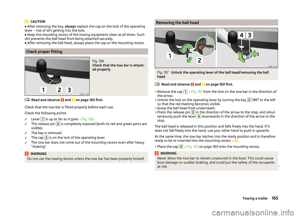
Check the following points. Lever
1
is up as far as it goes » Fig. 156.
The release pin
2
is completely exposed (both its red and green parts are
visible).
The key is removed.
The cap
3
is on the lock of the operating lever.
The tow bar does not come out of the mounting recess even after heavy
“shaking”.
WARNINGDo not use the towing device unless the tow bar has been properly locked!Removing the ball headFig. 157
Unlock the operating lever of the ball head/removing the ball
head
Read and observe
and on page 163 first.
›
Remove the cap
1
» Fig. 157 from the lock on the tow bar in the direction of
the arrow.
›
Unlock the lock on the operating lever by turning the key
2
180° to the left
so that the red marking becomes visible.
›
Grasp the ball head from underneath.
›
Press the release pin
3
in the direction of the arrow to the stop, and simul-
taneously push the lever
4
downwards in the direction of the arrow to the
stop.
The ball head is released in this position and falls freely into the hand. If it
does not fall freely into the hand, use your other hand to push it upwards.
At the same time, the tow bar latches into the ready position and is therefore
ready to be re-inserted into the mounting recess »
.
›
Place the cap
4
» Fig. 153 on page 163 onto the mounting recess.
WARNINGNever allow the tow bar to remain unsecured in the boot. This could cause
boot damage on sudden braking, and could put the safety of the occupants
at risk. 165Towing a trailer