ECU SKODA SUPERB 2014 2.G / (B6/3T) Owner's Guide
[x] Cancel search | Manufacturer: SKODA, Model Year: 2014, Model line: SUPERB, Model: SKODA SUPERB 2014 2.G / (B6/3T)Pages: 246, PDF Size: 17.16 MB
Page 105 of 246
WARNINGEnsure that the carrier rails and variable loading floor are correctly fastened
when installing the variable loading floor. If this is not the case, there is a
risk of injury for the occupants.
Extending variable loading floor with integrated aluminium rails
and faseting elements (Superb Combi)
Introduction
This chapter contains information on the following subjects:
Partial extension of variable load floor
103
Divide boot
103
Fit and remove variable loading floor
104
Fixing set
104
Movable lashing eyes
105
The variable loading floor makes handling of bulky items of luggage easier.
CAUTION
The maximum permissible load of the variable loading floor is 75 kg.
Note
The space below the variable loading floor can be used for stowing objects, for
example the fastening elements, removed foldable boot cover, etc.
Partial extension of variable load floor
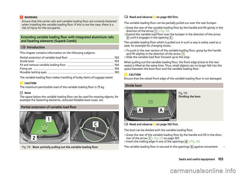
Fig. 112
Boot: partially pulling out the variable loading floor
Read and observe on page 103 first.
The variable loading floor can be partially pulled out over the rear bumper.
›
Grasp the rear of the variable loading floor by the handle and lift gently in the
direction of the arrow
1
» Fig. 112 .
›
Extend the variable load floor over the bumper in the direction of the arrow
2
until it engages in the opening
C
.
The variable loading floor which is pulled out in such a way is solely used as a
seat, for example for changing shoes.
›
To push in the rear section of the variable loading floor, grasp by the handle
and lift slightly in the direction of the arrow
1
.
›
Slide the variable load floor forward up to the stop.
When pulling out the variable loading floor, the front edge (close to the rear
seats) is lifted at the same time. Thus, small objects can no longer fall into the
space between the boot floor and the variable loading floor.
CAUTION
Ensure that the raised front edge of the variable loading floor is not damaged.
Divide boot
Fig. 113
Dividing the boot
Read and observe on page 103 first.
The boot can be divided with the variable loading floor.
›
Grasp the rear of the variable loading floor by the handle and lift in the direc-
tion of the arrow
1
» Fig. 112 on page 103 .
›
Insert the trailing edge in one of the openings
A
» Fig. 113 .
The variable loading floor is secured in the openings
A
against movement.
103Seats and useful equipment
Page 106 of 246
The variable loading floor can be pulled out a little more before dividing the
boot with the variable loading floor » page 103. This enlarges the space be-
tween the rear seats and the separation.
CAUTION
Ensure that the raised front edge of the variable loading floor is not damaged.
Fit and remove variable loading floor
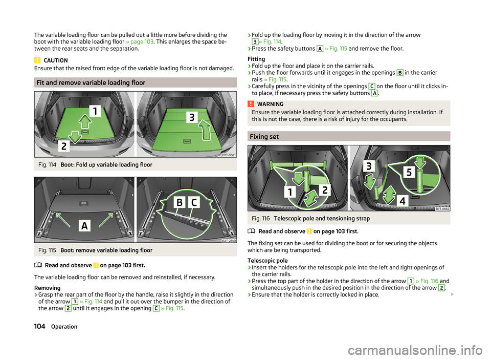
Fig. 114
Boot: Fold up variable loading floor
Fig. 115
Boot: remove variable loading floor
Read and observe
on page 103 first.
The variable loading floor can be removed and reinstalled, if necessary.
Removing
›
Grasp the rear part of the floor by the handle, raise it slightly in the direction
of the arrow
1
» Fig. 114 and pull it out over the bumper in the direction of
the arrow
2
until it engages in the opening
C
» Fig. 115 .
›Fold up the loading floor by moving it in the direction of the arrow3» Fig. 114
.›
Press the safety buttons
A
» Fig. 115 and remove the floor.
Fitting
›
Fold up the floor and place it on the carrier rails.
›
Push the floor forwards until it engages in the openings
B
in the carrier
rails » Fig. 115 .
›
Carefully press in the vicinity of the openings
C
on the floor until it clicks in-
to place, if necessary press the safety buttons
A
.
WARNINGEnsure the variable loading floor is attached correctly during installation. If
this is not the case, there is a risk of injury for the occupants.
Fixing set
Fig. 116
Telescopic pole and tensioning strap
Read and observe
on page 103 first.
The fixing set can be used for dividing the boot or for securing the objects
which are being transported.
Telescopic pole
›
Insert the holders for the telescopic pole into the left and right openings of
the carrier rails.
›
Press the top part of the holder in the direction of the arrow
1
» Fig. 116 and
simultaneously push in the desired position in the direction of the arrow
2
.
›
Ensure that the holder is correctly locked in place.
104Operation
Page 107 of 246
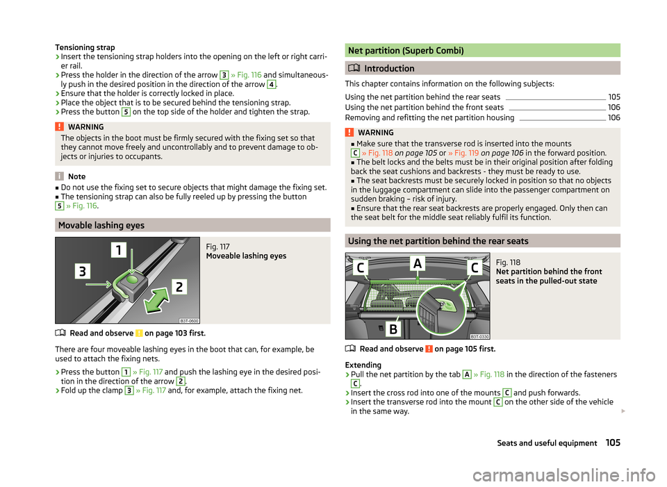
Tensioning strap›Insert the tensioning strap holders into the opening on the left or right carri-
er rail.›
Press the holder in the direction of the arrow
3
» Fig. 116 and simultaneous-
ly push in the desired position in the direction of the arrow
4
.
›
Ensure that the holder is correctly locked in place.
›
Place the object that is to be secured behind the tensioning strap.
›
Press the button
5
on the top side of the holder and tighten the strap.
WARNINGThe objects in the boot must be firmly secured with the fixing set so that
they cannot move freely and uncontrollably and to prevent damage to ob-
jects or injuries to occupants.
Note
■ Do not use the fixing set to secure objects that might damage the fixing set.■The tensioning strap can also be fully reeled up by pressing the button5
» Fig. 116 .
Movable lashing eyes
Fig. 117
Moveable lashing eyes
Read and observe on page 103 first.
There are four moveable lashing eyes in the boot that can, for example, be
used to attach the fixing nets.
›
Press the button
1
» Fig. 117 and push the lashing eye in the desired posi-
tion in the direction of the arrow
2
.
›
Fold up the clamp
3
» Fig. 117 and, for example, attach the fixing net.
Net partition (Superb Combi)
Introduction
This chapter contains information on the following subjects:
Using the net partition behind the rear seats
105
Using the net partition behind the front seats
106
Removing and refitting the net partition housing
106WARNING■ Make sure that the transverse rod is inserted into the mountsC » Fig. 118 on page 105 or » Fig. 119 on page 106 in the forward position.■
The belt locks and the belts must be in their original position after folding
back the seat cushions and backrests - they must be ready to use.
■
The seat backrests must be securely locked in position so that no objects
in the luggage compartment can slide into the passenger compartment on
sudden braking – risk of injury.
■
Ensure that the rear seat backrests are properly engaged. Only then can
the seat belt for the middle seat reliably fulfil its function.
Using the net partition behind the rear seats
Fig. 118
Net partition behind the front
seats in the pulled-out state
Read and observe on page 105 first.
Extending
›
Pull the net partition by the tab
A
» Fig. 118 in the direction of the fasteners
C
.
›
Insert the cross rod into one of the mounts
C
and push forwards.
›
Insert the transverse rod into the mount
C
on the other side of the vehicle
in the same way.
105Seats and useful equipment
Page 108 of 246
Retracting›Pull the transverse rod back slightly first on one side and then on the other
and remove it from the mounts C
» Fig. 118 .
›
Hold the cross rod in such a way that the net partition can slowly roll up into
the housing
B
without being damaged.
Note
If you wish to use the entire luggage compartment, the roll-up luggage com-
partment cover can be removed » page 99.
Using the net partition behind the front seats
Fig. 119
Net partition behind the front
seats in the pulled-out state
Read and observe on page 105 first.
Extending
›
Fold the rear seats forward » page 85.
›
Pull the net partition by the tab
A
» Fig. 119 .
›
First of all insert the cross rod into the mount
C
on one side and push it for-
ward.
›
Insert the transverse rod into the mount
C
on the other side of the vehicle
in the same way.
Retracting
›
Pull the transverse rod back slightly first on one side and then on the other
and remove it from the mounts
C
» Fig. 119 .
›
Hold the cross rod in such a way that the net partition can slowly roll up into
the housing
B
without being damaged.
›
Fold the rear seats back into their original positions » page 85.
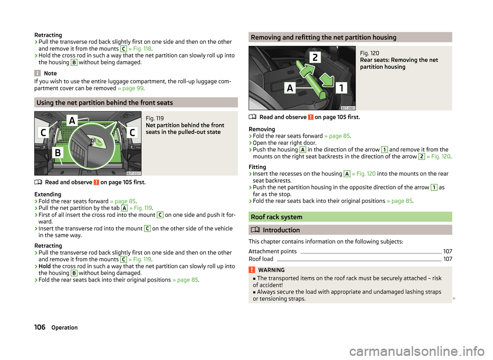
Removing and refitting the net partition housingFig. 120
Rear seats: Removing the net
partition housing
Read and observe on page 105 first.
Removing
›
Fold the rear seats forward » page 85.
›
Open the rear right door.
›
Push the housing
A
in the direction of the arrow
1
and remove it from the
mounts on the right seat backrests in the direction of the arrow
2
» Fig. 120 .
Fitting
›
Insert the recesses on the housing
A
» Fig. 120 into the mounts on the rear
seat backrests.
›
Push the net partition housing in the opposite direction of the arrow
1
as
far as the stop.
›
Fold the rear seats back into their original positions » page 85.
Roof rack system
Introduction
This chapter contains information on the following subjects:
Attachment points
107
Roof load
107WARNING■ The transported items on the roof rack must be securely attached – risk
of accident!■
Always secure the load with appropriate and undamaged lashing straps
or tensioning straps.
106Operation
Page 109 of 246
WARNING (Continued)■Distribute the load evenly over the roof rack system.■When transporting heavy objects or objects which take up a large area on
the roof rack system, the handling of the car may change as a result of the
displacement of the centre of gravity. The style of driving and speed must
therefore be adapted to the current circumstances.■
Avoid abrupt and sudden driving/braking manoeuvres.
■
Adjust the speed and driving style to the visibility, weather, road and traf-
fic conditions.
■
The permissible roof load, permissible axle loads and permissible total ve-
hicle weight must not be exceeded under any circumstances – risk of acci-
dent!
CAUTION
■ Only roof racks from the ŠKODA Original Accessories range should be used.■When dealing with roof racks, the installation instructions supplied with the
roof luggage rack system must be observed.■
On models fitted with a power sliding/tilting roof or a panoramic sliding roof,
ensure that the opened sliding/tilting roof or the panoramic sliding roof does
not strike any items of luggage transported on the roof.
■
Ensure that the boot lid does not hit the roof load when opened.
■
The height of the vehicle changes after mounting a roof luggage rack system
and the load that is secured to it. Compare the vehicle height with available
clearances, such as underpasses and garage doors.
■
Always remove the roof luggage rack system before entering an automated
car wash.
■
Ensure the roof aerial is not impaired by the secured load.
For the sake of the environment
The increased aerodynamic drag results in a higher fuel consumption.Attachment points
Does not apply to the Superb Combi.Fig. 121
Attachment points for roof bars
Read and observe
and on page 106 first.
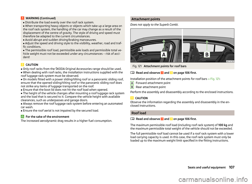
Installation position of the attachment points for roof bars » Fig. 121:
Forward attachment point
Rear attachment point
Perform the assembly and disassembly according to the enclosed instructions.
CAUTION
Observe the information regarding the assembly and disassembly in the en-
closed instructions.
Roof load
Read and observe
and on page 106 first.
The maximum permissible roof load (including roof rack system) of 100 kg and
the maximum permissible total weight of the vehicle should not be exceeded.
The full permissible roof load cannot be used if a roof rack system with a lower
load carrying capacity is used. In this case, the roof rack system must only be
loaded up to the maximum weight limit specified in the fitting instructions.
AB107Seats and useful equipment
Page 136 of 246
Ejecting all CDs›Press and hold the button A » Fig. 131 for more than 2 seconds. All CDs in
the CD-changer are ejected consecutively.
Note
■ Insert a CD, with the labelled side facing up, into the CD slot B » Fig. 131 until
it is automatically drawn in. The play function will start automatically.■
After loading a CD into the CD changer, wait until the indicator light of the
corresponding button
D
is illuminated. Then the CD case
B
is free to load the
next CD.
■
If a position is selected, on which a CD is already located, this CD is ejected.
Remove the ejected CD and load the desired CD.
DVD-preinstallation
Fig. 132
Seat backrest - left front seat/right front seat
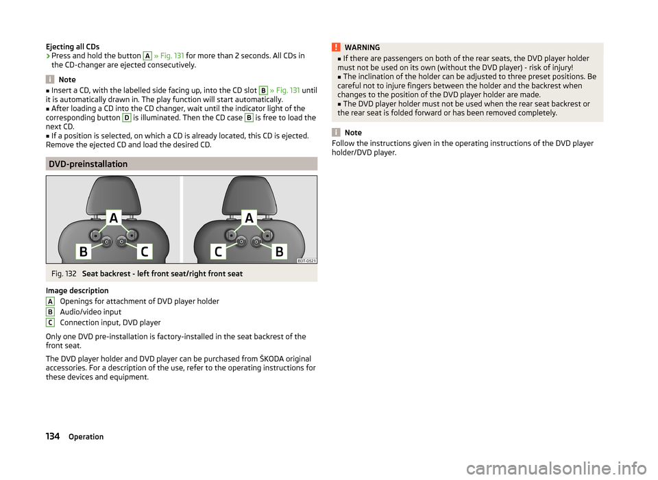
Image description Openings for attachment of DVD player holder
Audio/video input
Connection input, DVD player
Only one DVD pre-installation is factory-installed in the seat backrest of the
front seat.
The DVD player holder and DVD player can be purchased from ŠKODA original
accessories. For a description of the use, refer to the operating instructions for
these devices and equipment.
ABCWARNING■ If there are passengers on both of the rear seats, the DVD player holder
must not be used on its own (without the DVD player) - risk of injury!■
The inclination of the holder can be adjusted to three preset positions. Be
careful not to injure fingers between the holder and the backrest when
changes to the position of the DVD player holder are made.
■
The DVD player holder must not be used when the rear seat backrest or
the rear seat is folded forward or has been removed completely.
Note
Follow the instructions given in the operating instructions of the DVD player
holder/DVD player.134Operation
Page 165 of 246
Towing a trailer
Towing device
Introduction
This chapter contains information on the following subjects:
Description
163
Adjusting the ready position
164
Fitting the ball head
164
Check proper fitting
165
Removing the ball head
165
Use and care
166
If your vehicle has already been factory-fitted with a towing device or is fitted
with a towing device from ŠKODA Original Accessories, then it meets all of the
technical requirements and national legal regulations for towing a trailer.
Your vehicle is fitted with a 13-pin power socket for the electrical connection
between the vehicle and trailer. If the trailer that is to be towed has a 7-pin
connector , you can use a suitable adapter from ŠKODA Original Accessories.
The maximum trailer drawbar load is 80 kg.
WARNING■
Check that the tow bar is seated correctly and is secured in the mounting
recess before the start of every journey.■
Do not use the tow bar if it is not correctly inserted and secured in the
mounting recess.
■
Do not use the towing device if it is damaged or if there are parts missing.
■
Do not modify or adapt the towing device in any way.
■
Never release the tow bar while the trailer is still coupled.
CAUTION
Take care when handling the tow bar so as to avoid damaging the paintwork
on the bumper.DescriptionFig. 153
Carrier for the towing device/tow bar
Read and observe
and on page 163 first.
The tow bar can be removed and is kept in the spare wheel compartment or in
a compartment for the spare wheel in the boot » page 201, Vehicle tool kit .
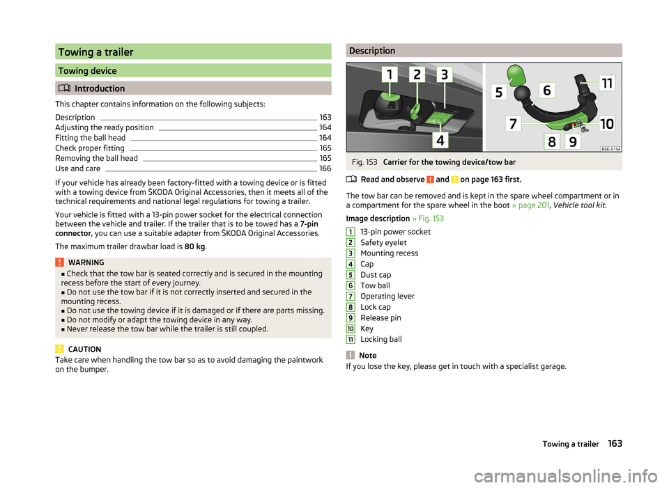
Image description » Fig. 153
13-pin power socket
Safety eyelet
Mounting recess
Cap
Dust cap
Tow ball
Operating lever
Lock cap
Release pin
Key
Locking ball
Note
If you lose the key, please get in touch with a specialist garage.1234567891011163Towing a trailer
Page 166 of 246
Adjusting the ready positionFig. 154
Setting the ready position/ready position
Read and observe
and on page 163 first.
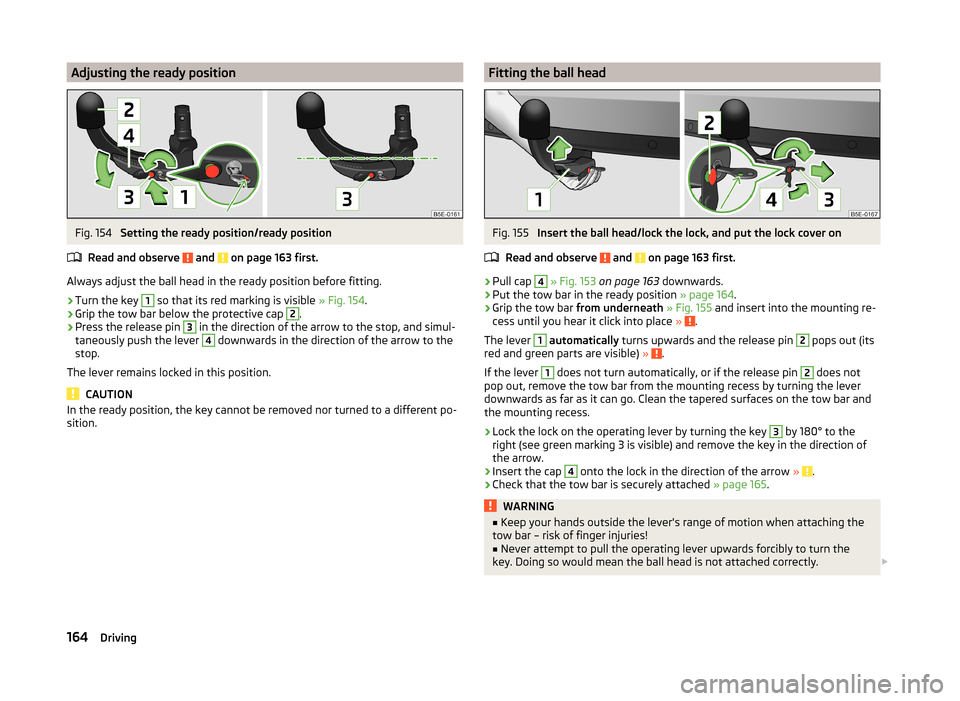
Always adjust the ball head in the ready position before fitting.
›
Turn the key
1
so that its red marking is visible » Fig. 154.
›
Grip the tow bar below the protective cap
2
.
›
Press the release pin
3
in the direction of the arrow to the stop, and simul-
taneously push the lever
4
downwards in the direction of the arrow to the
stop.
The lever remains locked in this position.
CAUTION
In the ready position, the key cannot be removed nor turned to a different po-
sition.Fitting the ball headFig. 155
Insert the ball head/lock the lock, and put the lock cover on
Read and observe
and on page 163 first.
›
Pull cap
4
» Fig. 153 on page 163 downwards.
›
Put the tow bar in the ready position » page 164.
›
Grip the tow bar from underneath » Fig. 155 and insert into the mounting re-
cess until you hear it click into place » .
The lever
1
automatically turns upwards and the release pin
2
pops out (its
red and green parts are visible) » .
If the lever
1
does not turn automatically, or if the release pin
2
does not
pop out, remove the tow bar from the mounting recess by turning the lever
downwards as far as it can go. Clean the tapered surfaces on the tow bar and
the mounting recess.
›
Lock the lock on the operating lever by turning the key
3
by 180° to the
right (see green marking 3 is visible) and remove the key in the direction of
the arrow.
›
Insert the cap
4
onto the lock in the direction of the arrow » .
›
Check that the tow bar is securely attached » page 165.
WARNING■
Keep your hands outside the lever's range of motion when attaching the
tow bar – risk of finger injuries!■
Never attempt to pull the operating lever upwards forcibly to turn the
key. Doing so would mean the ball head is not attached correctly.
164Driving
Page 167 of 246
CAUTION■After removing the key, always replace the cap on the lock of the operating
lever – risk of dirt getting into the lock.■
Keep the mounting recess of the towing equipment clean at all times. Such
dirt prevents the ball head from being attached securely.
■
After removing the ball head, always place the cap on the mounting recess.
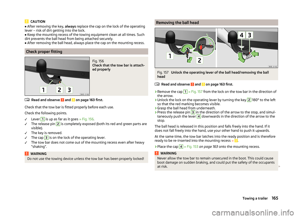
Check proper fitting
Fig. 156
Check that the tow bar is attach-
ed properly
Read and observe and on page 163 first.
Check that the tow bar is fitted properly before each use.
Check the following points. Lever
1
is up as far as it goes » Fig. 156.
The release pin
2
is completely exposed (both its red and green parts are
visible).
The key is removed.
The cap
3
is on the lock of the operating lever.
The tow bar does not come out of the mounting recess even after heavy
“shaking”.
WARNINGDo not use the towing device unless the tow bar has been properly locked!Removing the ball headFig. 157
Unlock the operating lever of the ball head/removing the ball
head
Read and observe
and on page 163 first.
›
Remove the cap
1
» Fig. 157 from the lock on the tow bar in the direction of
the arrow.
›
Unlock the lock on the operating lever by turning the key
2
180° to the left
so that the red marking becomes visible.
›
Grasp the ball head from underneath.
›
Press the release pin
3
in the direction of the arrow to the stop, and simul-
taneously push the lever
4
downwards in the direction of the arrow to the
stop.
The ball head is released in this position and falls freely into the hand. If it
does not fall freely into the hand, use your other hand to push it upwards.
At the same time, the tow bar latches into the ready position and is therefore
ready to be re-inserted into the mounting recess »
.
›
Place the cap
4
» Fig. 153 on page 163 onto the mounting recess.
WARNINGNever allow the tow bar to remain unsecured in the boot. This could cause
boot damage on sudden braking, and could put the safety of the occupants
at risk. 165Towing a trailer
Page 168 of 246
CAUTION■If the lever is held firm and not pushed downwards as far as it can go, it will
go back up after the ball head is removed and will not latch into the ready po-
sition. The tow bar will then need to be brought into this position before the
next time it is fitted.■
Stow the ball head in the ready position with the key inserted in the box.
When doing so, make the side opposite to the inserted key face downwards –
there is a risk of damaging the key.
■
Do not use excessive force when handling the operating lever (e.g. do not
step on it).
Note
■ We recommend putting the protective cover onto the ball head before re-
moving the tow bar.■
Clean any dirt from the tow bar before stowing it away in the box with the
vehicle tool kit.
Use and care
Read and observe
and on page 163 first.
Close the mounting recess with the cover to prevent any dirt from getting in.
Always check the tow bar before hitching a trailer. Apply suitable grease
where necessary.
Use the protective cover when stowing away the tow bar, in order to stop the
boot from getting dirty.
In the event of dirt, clean the surfaces of the mounting recess and treat with a
suitable preservative.
CAUTION
Apply grease to the upper part of the mounting recess. Make sure you do not
remove any grease.
Trailer
Introduction
This chapter contains information on the following subjects:
Loading a trailer
166
Driving with a trailer
167Trailer stabilisation (TSA)168Anti-theft alarm system168WARNINGAlways drive particularly carefully with the trailer.
Loading a trailer
Read and observe
on page 166 first.
The vehicle/trailer combination must be balanced, whereby the maximum per-
missible drawbar load must be utilised. If the drawbar load is too low, it jeop-
ardises the performance of the vehicle/trailer combination.
Distribution of the load
Distribute the load in the trailer in such a way that heavy items are located as
close to the axle as possible. Secure the items from slipping.
The distribution of the weight is very poor if your vehicle is unladen and the
trailer is laden. Maintain a particularly low speed if you cannot avoid driving
with this combination.
Tyre pressure
Correct the tyre inflation pressure on your vehicle for a “full load” » page 194,
Service life of tyres .
Trailer load
The permissible trailer load must not be exceeded under any circumstan- ces » page 224 , Technical data .
The trailer loads specified apply only to altitudes up to 1 000 metres above
mean sea level.
The engine output falls as altitude increases, as does the vehicle's climbing
power. Therefore, for every additional 1000 m in height (or part), the maximum
permissible towed weight must be reduced by 10%.
The towed weight is made up of the actual weights of the loaded towing vehi-
cle and the loaded trailer.
The trailer and drawbar load information on the type plate of the towing de-
vice is merely a test value for the towing device. The vehicle-specific values
are detailed in the vehicle documents.
166Driving