low oil pressure SKODA SUPERB 2014 2.G / (B6/3T) Owner's Manual
[x] Cancel search | Manufacturer: SKODA, Model Year: 2014, Model line: SUPERB, Model: SKODA SUPERB 2014 2.G / (B6/3T)Pages: 246, PDF Size: 17.16 MB
Page 8 of 246
Safety
Passive Safety
General information
Introduction
This chapter contains information on the following subjects:
Before setting off
6
Driving safety
6
Safety equipment
6
In this section you will find important information, tips and notes on the sub-
ject of passive safety in your vehicle.
We have combined everything here which you should be familiar with, for ex-
ample, regarding seat belts, airbags, child seats and safety of children.
WARNING■ This chapter contains important information on how to use the vehicle for
the driver and his occupants.■
You can find further information on safety concerning you and those trav-
elling with you in the following chapters of this owner's manual.
■
The complete on-board literature should always be in the vehicle. This
applies in particular, if you rent out or sell the vehicle.
Before setting off
Read and observe
on page 6 first.
For your own safety and the safety of the people travelling with you, please
pay attention to the following points before setting off.
Ensure that the lighting and the turn signal system are functioning proper-
ly.
Ensure that the function of the wiper and the condition of the wiper
blades are free of any defects.
Ensure that all of the windows offer good visibility to the outside.
Adjust the rear-view mirror so that vision to the rear is guaranteed.
Ensure that the mirrors are not covered.
Check the tyre inflation pressure.
Check the engine oil, brake fluid and coolant level.
Secure all items of luggage.
Do not exceed the permissible axle loads and permissible gross weight of
the vehicle.
Close all doors as well as the bonnet and boot lid.
Ensure that no objects can obstruct the pedals.
Protect children in suitable child seats with correctly fastened seat
belts » page 21 , Transporting children safely .
Adopt the correct seated position » page 7, Correct and safe seated
position . Tell your passengers to assume the correct seated position.
Driving safety
Read and observe
on page 6 first.
The driver is fully responsible for himself and his occupants. If your driving
safety is effected, you place yourself and the oncoming traffic at risk.
The following guidelines must therefore be observed. Do not become distracted from concentrating on the traffic situation, e.g.
by your passengers or mobile phone calls.
Never drive when your driving ability is impaired, e.g. due to medication, al-
cohol or drugs.
Keep to the traffic regulations and the permissible speed limit.
Always adjust the driving speed to the road, traffic and weather condi-
tions.
Take regular breaks on long journeys – at least every two hours.
Safety equipment
Read and observe
on page 6 first.
The following list contains only part of the safety equipment in your vehicle.
› Three-point seat belts for all the seats.
› Belt force limiter for front and outer rear seats.
› Belt tensioner for front and outer rear seats.
› Seat belt height adjusters for the front seats.
› Front airbag for the driver and the front passenger.
› Driver’s knee airbag.
6Safety
Page 33 of 246
Display of the second speedRead and observe
on page 28 first.
The display can show the current speed in mph 1)
.
This feature is provided for driving in countries with different speed units.
Maxi DOT display
The display of the second speed can be set in the Alt. speed dis. menu
item » page 45 , Settings .
Segment display
›
Press key
3
» Fig. 20 on page 28 repeatedly, until the odometer display
flashes » page 30 .
›
Press the
7
key while the display flashes.
The second speed is displayed instead of the odometer.
The display of the second speed can be disabled in the same way.
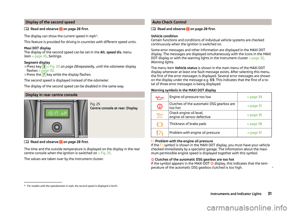
Display in rear centre console
Fig. 25
Centre console at rear: Display
Read and observe on page 28 first.
The time and the outside temperature is displayed on the display in the rear
centre console when the ignition is switched on » Fig. 25.
The values are taken over by the instrument cluster.
Auto Check Control
Read and observe
on page 28 first.
Vehicle condition
Certain functions and conditions of individual vehicle systems are checked
continuously when the ignition is switched on.
Some error messages and other information are displayed in the MAXI DOT
display. The messages are displayed simultaneously with the icons in the MAXI
DOT display or with the warning lights in the instrument cluster » page 32,
Warning lights .
The menu item Vehicle status is shown in the main menu of the MAXI DOT
display whenever at least one fault message exists. After selecting this menu,
the first of the error messages is displayed. Several error messages are shown
on the display under the message e.g. 1/3. This indicates that the first of a to-
tal of three error messages is being displayed.
Warning symbols in the MAXI DOT display
Engine oil pressure too low» page 34Clutches of the automatic DSG gearbox are
too hot» page 31Check engine oil level,
engine oil sensor defective» page 35Thickness of brake pads» page 38Problem with engine oil pressure» page 31
Problem with the engine oil pressure
If the symbol is shown in the MAXI DOT display, you must have your vehicle
checked immediately by a specialist garage. The information about the maxi-
mum permissible engine speed is displayed together with this symbol.
Clutches of the automatic DSG gearbox are too hot
If the symbol appears in the MAXI DOT display, this indicates that the tem-
perature of the automatic DSG gearbox clutched is too high.
1)
For models with the speedometer in mph, the second speed is displayed in km/h.
31Instruments and Indicator Lights
Page 34 of 246
The following message is shown in the MAXI DOT display.Gearbox overheated. Stop! Log book!
do not continue to drive! Stop the vehicle, switch off the engine, and wait
until the
icon goes out – risk of gearbox damage! You can continue your
journey as soon as the symbol disappears.WARNINGIf you have to stop for technical reasons, then park the vehicle at a safe
distance from the traffic, switch off the engine and activate the hazard
warning lights system » page 70. The warning triangle must be set up at
the prescribed distance - observe the national legal provisions when doing
so.
Note
■ If the MAXI DOT display shows warning messages, these messages must be
confirmed in order to access the main menu » page 40 .■
As long as the operational faults are not rectified, the symbols are always in-
dicated again. After they are displayed for the first time, the symbols continue
to be indicated without any extra messages for the driver.
Warning lights
Introduction
This chapter contains information on the following subjects:
Handbrake
33
Brake system
33
Seat belt warning light
33
Generator
33
Door open
34
Engine oil pressure
34
Coolant
34
Bonnet
34
Boot lid
34
Power steering / steering lock (system KESSY)
34
Engine oil level
35
Traction Control System (ASR)
35
Electronic Stability Control (ESC)
35 Antilock brake system (ABS)36 Rear fog light36
Lamp failure
36
Adaptive headlights (AFS)
36
Exhaust inspection system
36
Glow plug system (diesel engine)
36
Engine performance check (petrol engine)
37
Diesel particulate filter (diesel engine)
37
Fuel reserve
37
Airbag system
38
Tyre inflation pressure
38
Windscreen washer fluid level
38
Pads
38
Turn signal system
38
Low beam
39
Fog lights
39
Cruise control system
39
Selector lever lock / starter (system KESSY)
39
Main beam
39
The warning lights indicate certain functions or faults.
Some warning lights can be accompanied by acoustic signals and messages in
the display of the instrument cluster.
After switching on the ignition, some warning lights illuminate briefly as a
function test.
If the tested systems are OK, the corresponding warning lights go out a few
seconds after switching on the ignition or after starting the engine.
32Operation
Page 36 of 246
Door openRead and observe
on page 33 first.
The indicator light
illuminates if one or several doors are opened.
Engine oil pressure
Read and observe
on page 33 first.
When the warning light is flashing
, the engine oil pressure is too low.
The following message is shown in the MAXI DOT display. Oil pressure: Log book!
›
Stop the vehicle, switch off the engine, and check the engine oil lev-
el » page 186 .
If the warning light flashes,
do not drive any further , even if the oil level is
correct! Also do not leave the engine running at an idling speed.
Seek help from a specialist garage.
Coolant
Read and observe
on page 33 first.
If the warning light
lights up or flashes , either the coolant temperature is
too high or the coolant level is too low.
The following message is shown in the MAXI DOT display. Check coolant! Log book!
›
Stop the vehicle, switch off the engine, and check the coolant lev-
el » page 188 .
›
If the coolant level is too low, add coolant to the reservoir » page 188.
If the indicator light
does not illuminate after adding coolant and switching
on the ignition, you may continue your journey.
If the coolant level is within the specified range and the indicator light is still
illuminated, then there may be a malfunction of the cooling fan.
›
Check the fuse for the radiator fan, replace if necessary » page 217, Fuses in
the engine compartment .
If the coolant level and fan fuse are both OK but the indicator light is still
illuminated , do not continue your journey!
Seek help from a specialist garage.WARNING■ Carefully open the coolant expansion bottle. If the engine is hot, the cool-
ing system is pressurized - risk of scalding! It is therefore best to allow the
engine to cool down before removing the cap.■
Do not touch the radiator fan. The radiator fan may switch itself on auto-
matically even if the ignition is off.
CAUTION
■ Additional headlights and other attached components in front of the air inlet
impair the cooling efficiency of the coolant.■
Never cover the radiator - there is a risk of the engine overheating.
Bonnet
Read and observe
on page 33 first.
The indicator light
illuminates if the bonnet is unlocked.
Boot lid
Read and observe
on page 33 first.
The indicator light
illuminates if the boot lid is opened.
Power steering / steering lock (system KESSY)
Read and observe
on page 33 first.
Power steering
If the indicator light
illuminates , this indicates a partial failure of the power
steering and the steering forces can be greater.
If the indicator light
illuminates , this indicates a complete failure of the
power steering and the steering assist has failed (significantly higher steering
forces).
›
Stop the car, turn the ignition off and on again.
The powered steering is fully functional again if the
or
warning light does
not illuminate after you switch the engine back on.
34Operation
Page 142 of 246
Emergency ignition shutoff systemRead and observe
and on page 137 first.
The ignition can be turned off in an emergency even when travelling at a
speed of more than 2 km / hr.
›
Press the starter button » Fig. 134 on page 138 for longer than 1 second or
twice within 1 second.
After emergency stop of the ignition, the steering is unlocked.
Brakes
Introduction
This chapter contains information on the following subjects:
Information on braking
140
Handbrake
141WARNING■ Greater physical effort is required for braking when the engine is switch-
ed off – risk of accident!■
The clutch pedal must be actuated when braking on a vehicle with man-
ual transmission, when the vehicle is in gear and at low revs. Otherwise,
the function of the brake booster may be impaired – risk of accident!
■
When leaving the vehicle, never leave persons who might, for example,
release the handbrake or take the vehicle out of gear unattended in the ve-
hicle. The vehicle could then start to move – risk of accident!
WARNINGIn the case of damage to the standard fitted front spoiler or if retrofitting
another front spoiler, hub caps etc. » page 169, Services, modifications,
and technical alterations , make sure that the air supply to the front brakes
is not affected. The front brakes may overheat, which can have a negative
impact on the functioning of the braking system – risk of accident!
CAUTION
■ Observe the recommendations on the new brake pads » page 145.■Never let the brakes slip with light pressure on the pedal if braking is not
necessary. This causes the brakes to overheat and can also result in a longer
braking distance and excessive wear.Information on braking
Read and observe
and on page 140 first.
If the brakes are applied in full and the control unit for the braking system con-siders the situation to be dangerous for the following traffic, the brake light
flashes automatically.
After the speed was reduced below around 10 km/h or the vehicle was stop-
ped, the brake light stops flashing and the hazard warning light system
switches on. The hazard warning light system is switched off automatically af- ter accelerating or driving off again.
Before travelling a long distance with a steep gradient, reduce speed and shift
into the next lowest gear. As a result, the braking effect of the engine will be
used, reducing the load on the brakes. Any additional braking should be com-
pleted intermittently, not continuously.
Wear-and-tear
The wear of the brake pads is dependent on the operating conditions and driv-
ing style.
The brake pads wear more quickly if a lot of journeys are completed in towns
and over short distances or if a very sporty style of driving is adopted.
Under these severe conditions , the thickness of the brake pads must also be
checked by a specialist garage between service intervals.
Wet roads or road salt
The performance of the brakes can be delayed as the brake discs and brake
pads may be moist or have a coating of ice or layer of salt on them in winter.
The brakes are cleaned and dried by applying the brakes several times.
Corrosion
Corrosion on the brake discs and dirt on the bake pads occur if the vehicle has been parked for a long period and if you do not make much use of the braking
system. The brakes are cleaned and dried by applying the brakes several times.
Faults in the brake surface
If it is found that the braking distance has suddenly become longer and that
the brake pedal can be depressed further, the brake system may be faulty.
Visit a specialist garage immediately and adjust your style of driving appropri-
ately, as you will not know the exact extent of the damage.
140Driving
Page 175 of 246
Automatic car wash systemsRead and observe
and on page 172 first.
The usual precautionary measures must be taken before washing the vehicle
in an automatic car wash system (e.g. closing the windows and the sliding/tilt-
ing roof etc.).
If your vehicle is fitted with any particular attached parts, such as a spoiler,
roof rack system, two-way radio aerial etc., it is best to consult the operator of
the car wash system beforehand.
After an automatic wash with wax treatment, the lips of the wipers should be
cleaned with cleaning agents specially designed for the purpose, and then de-
greased.
WARNINGFold in the exterior mirrors to prevent damage before washing the vehicle
in an automatic car wash system. Never manually fold in electric exterior
mirrors - always use the electric controls.
Washing with a high-pressure cleaner
Read and observe
and on page 172 first.
When washing the vehicle with a high-pressure cleaner, the instructions for
use of the equipment must be observed. This applies in particular to the pres-
sure used and to the spraying distance .
Maintain a sufficiently large distance to the parking aid sensors and soft mate-
rials such as rubber hoses or insulation material.
WARNINGNever use circular spray nozzles or dirt cutters!
CAUTION
■ If washing the vehicle in the winter using a hose or high-pressure cleaner,
ensure that the jet of water is not aimed directly at the locking cylinders or the
door/panel joints – risk of freezing!■
To avoid damaging the parking aid sensors while cleaning with high-pressure
cleaners or steam jets, the sensors must only be directly sprayed for short pe-
riods while a minimum distance of 10 cm must be observed.
■ The temperature of the water used for cleaning must not exceed 60 °C – risk
of damaging the vehicle.■
See also Washing cars with decorative films using a high-pressure clean-
er » page 175 .
Taking care of your vehicle exterior
Introduction
This chapter contains information on the following subjects:
Taking care of your vehicle's paintwork
174
Plastic parts
174
Rubber seals
174
Chrome parts
174
Decorative films
175
Windows and exterior mirrors
175
Headlight lenses
175
Door lock cylinders
175
Cavity protection
176
Wheels
176
Underbody protection
176
Regular and proper care help to retain the efficiency and value of your vehicle.
It may also be one of the requirements for the acceptance of warranty claims
relating to corrosion damage and paint defects on the bodywork.
We recommend using vehicle care products from ŠKODA Original Accessories.
These are available from ŠKODA Partners. The usage instructions on the pack-
age must be observed.
WARNING■ Vehicle care products may be harmful to your health if not used according
to the instructions.■
Always keep the vehicle care products safe from people who are not com-
pletely independent, e.g. children - there is a danger of poisoning!
■
Protect your hands and arms from sharp-edged metal parts when clean-
ing the underfloor, the inside of the wheel housings or the wheel trims –
risk of cuts!
173Car care
Page 196 of 246
WARNINGInformation regarding tyre damage or wear■Never use tyres if you do not know anything about the condition and age.■
Never drive with damaged tyres – risk of accident!
■
Immediately replace damaged wheel rims or tyres.
■
You must have your tyres replaced with new ones at the latest when the
wear indicators have been worn down.
■
Worn tyres impair necessary adhesion to the road surface, particularly at
high speeds on wet roads. This could lead to “aquaplaning” (uncontrolled
vehicle movement – “swimming” on a wet road surface).
WARNINGInformation on tyre pressure■The tyre control display does not absolve the driver of the responsibility
to ensure the correct tyre inflation pressure. Check the tyre inflation pres-
sure at regular intervals.■
Insufficient or excessive inflation pressure impairs handling – risk of acci-
dent!
■
If the inflation pressure is too low, the tyre will have to overcome a higher
rolling resistance. This will cause a significant increase in the temperature
of the tyre, especially at higher speeds. This can result in tread separation
and a tyre blowout.
WARNINGInformation on the wheel bolts■The wheel bolts must be clean and must turn easily. Never treat them
with grease or oil.■
The prescribed tightening torque of the wheel bolts for steel and light al-
loy wheels is 120 Nm.
■
If the wheel bolts are tightened to a too low tightening torque, the rims
could come loose when the car is moving – risk of accident! A tightening
torque which is too high can damage the bolts and threads and this can re-
sult in permanent deformation of the contact surfaces on the rims.
■
In case of incorrect treatment of the wheel bolts, the wheel can loosen
when the car is moving – risk of accident!
WARNINGInformation on the temporary spare wheel■Only use the temporary spare wheel when absolutely necessary.■
Never drive with more than one temporary spare wheel mounted.
■
The snow chains cannot be used on the temporary spare wheel.
CAUTION
■ If a spare wheel is used that is not identical to the fitted tyres, the following
must be observed » page 197, Spare and temporary spare wheel .■
Protect the tyres from contact with oil, grease and fuel.
■
Replace lost valve caps.
■
If, in the event of a puncture, it is necessary to fit a spare wheel with a tyre
without a dedicated running direction or with the opposite direction of rota-
tion, drive carefully as the optimal characteristics of the tyre are no longer ap-
plicable in this situation.
For the sake of the environment
Tyres that are insufficiently inflated increase your fuel consumption.
Note
■ We recommend that any work on the wheels or tyres be carried out by a spe-
cialist garage.■
We recommend that you use wheel rims, tyres, full wheel trims and snow
chains from ŠKODA Original Accessories.
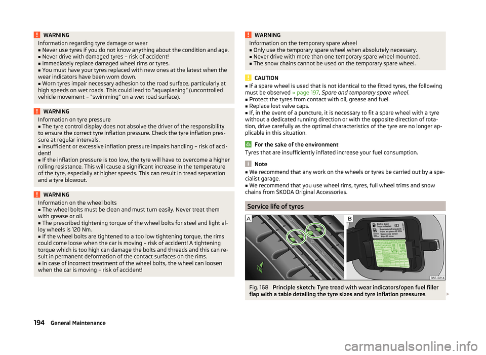
Service life of tyres
Fig. 168
Principle sketch: Tyre tread with wear indicators/open fuel filler
flap with a table detailing the tyre sizes and tyre inflation pressures
194General Maintenance
Page 218 of 246
CAUTION■“Never repair” fuses or replace them with a fuse of a higher amperage – risk
of fire! This may also cause damage at another part of the electrical system.■
If a newly inserted fuse blows again after a short time, have the electrical
system checked as quickly as possible by a specialist garage.
■
A blown fuses is recognisable by the molten metal strip. Replace the faulty
fuse with a new one of the same amperage.
Note
■
We recommend always carrying replacement fuses in the vehicle. A box of
replacement fuses can be purchased from ŠKODA Original Accessories.■
There can be several power consuming devices for one fuse.
■
Multiple fuses may exist for a single power consuming device.
Fuses in the dash panel
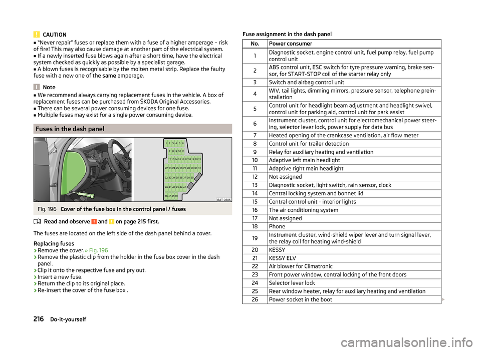
Fig. 196
Cover of the fuse box in the control panel / fuses
Read and observe
and on page 215 first.
The fuses are located on the left side of the dash panel behind a cover.
Replacing fuses
›
Remove the cover. » Fig. 196
›
Remove the plastic clip from the holder in the fuse box cover in the dash
panel.
›
Clip it onto the respective fuse and pry out.
›
Insert a new fuse.
›
Return the clip to its original place.
›
Re-insert the cover of the fuse box .
Fuse assignment in the dash panelNo.Power consumer1Diagnostic socket, engine control unit, fuel pump relay, fuel pump
control unit2ABS control unit, ESC switch for tyre pressure warning, brake sen-
sor, for START-STOP coil of the starter relay only3Switch and airbag control unit4WIV, tail lights, dimming mirrors, pressure sensor, telephone prein-
stallation5Control unit for headlight beam adjustment and headlight swivel,
control unit for parking aid, control unit for park assist6Instrument cluster, control unit for electromechanical power steer-
ing, selector lever lock, power supply for data bus7Heated opening of the crankcase ventilation, air flow meter8Control unit for trailer detection9Relay for auxiliary heating and ventilation10Adaptive left main headlight11Adaptive right main headlight12Not assigned13Diagnostic socket, light switch, rain sensor, clock14Central locking system and bonnet lid15Central control unit - interior lights16The air conditioning system17Not assigned18Phone19Instrument cluster, wind-shield wiper lever and turn signal lever,
the relay coil for heating wind-shield20KESSY21KESSY ELV22Air blower for Climatronic23Front power window, central locking of the front doors24Selector lever lock25Rear window heater, relay for auxiliary heating and ventilation26Power socket in the boot 216Do-it-yourself
Page 221 of 246
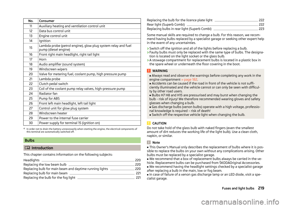
No.Consumer11Auxiliary heating and ventilation control unit12Data bus control unit13Engine control unit14Ignition15Lambda probe (petrol engine), glow plug system relay and fuel
pump (diesel engine)16Front right main headlight, right tail light17Horn18Audio amplifier (sound system)19Windscreen wipers20Valve for metering fuel, coolant pump, high pressure pump21Lambda probe22Clutch pedal switch23Coil of the coolant pump relay valves, high-pressure pump24Radiator fan25Pump for ABS26Front left main headlight, left tail light27Control unit for glow plug system28Windscreen heater29Power to the internal fuse carrier30Power supply for terminal 15 (ignition on)a)
In order not to drain the battery unnecessarily when starting the engine, the electrical components of
this terminal are automatically switched off.
Bulbs
Introduction
This chapter contains information on the following subjects:
Headlights
220
Replacing the low beam bulb
220
Replacing bulb for main beam and daytime running lights
220
Replacing bulb for main beam
221
Replacing the bulb for the fog light
221Replacing the bulb for the licence plate light222Rear light (Superb Combi)222
Replacing bulbs in rear light (Superb Combi)
223
Some manual skills are required to change a bulb. For this reason, we recom-
mend having bulbs replaced by a specialist garage or seeking other expert help
in the event of any uncertainties.
› Switch off the ignition and all of the lights before replacing a bulb.
› Faulty bulbs must only be replaced with the same type of bulbs. The designa-
tion is located on the light socket or the glass bulb.
› A stowage compartment for replacement bulbs is located in a plastic box in
the spare wheel or underneath the floor covering in the boot.
WARNING■ Always read and observe the warnings before completing any work in the
engine compartment » page 182.■
Accidents can be caused if the road in front of the vehicle is not suffi-
ciently illuminated and the vehicle cannot or can only be seen with difficul-
ty by other road users.
■
Bulbs H7 H8 and H15 are pressurised and may burst when changing the
bulb - risk of injury! We therefore recommended wearing gloves and safety
glasses when changing a bulb.
■
Gas discharge bulbs (xenon bulbs) operate with a high voltage, professio-
nal knowledge is required – risk of death!
■
Switch off the respective vehicle light when changing the bulb.
CAUTION
Do not take hold of the glass bulb with naked fingers (even the smallest
amount of dirt reduces the working life of the light bulb). Use a clean cloth,
napkin, or similar.
Note
■ This Owner's Manual only describes the replacement of bulbs where it is pos-
sible to replace the bulbs on your own without any complications arising. Other
bulbs must be replaced by a specialist garage.■
We recommend that a box of replacement bulbs always be carried in the ve-
hicle. Replacement bulbs can be purchased from ŠKODAOriginal Accessories.
■
We recommend having the headlight settings checked by a specialist garage
after replacing a bulb in the main, low or fog beam.
■
In case of failure of a xenon gas discharge lamp or an LED diode, visit a spe-
cialist garage.
219Fuses and light bulbs
Page 237 of 246
Unlocking the driver's door212
Unlocking the tailgate212
Emergency equipment Fire extinguisher
200
First aid kit200
Jack201
Vehicle tool kit201
Warning triangle200
Emissions225
Engine Running in
145
Engine compartment182
Brake fluid189
Coolant188
Overview184
Vehicle battery189
Engine number224
Engine oil185
Capacity185
Changing187
Checking186
Information message34
Replenishing187
Specifications185
Engine oil level Warning light
35
Engine oil pressure Warning light
34
Entry lighting73
Environment146
Environmental compatibility148
Environmentally friendly driving146
EPC Warning light
37
ESC Function
151
Warning light35
Exhaust inspection system Warning light
36
Extending variable loading flooPartial extension103
Extending variable loading floor103
Divide boot103
Movable lashing eyes105
Extrending variable loading floor Fixing set
104
F
Fastening elements
97
Fatigue detection162
Function162
Information messages162
Films175
Fire extinguisher200
First aid kit200
Floor covering Fixing
98
Fog lights69
Warning light39
Fog lights with CORNER function69
Folding hook97
Fold in passenger's mirror78
Footmats142
see footmats142
Force limit Electric boot lid (Superb Combi)
57
Power windows61
Sliding/tilting roof62
Sliding/tilting roof (Superb Combi)64
Front airbag15
Front door warning light72
Front interior light71
Fuel179
Diesel181
Fuel gauge30
refer to Fuel179
Refuelling180
Unleaded petrol180
Fuel consumption146, 225
Fuel reserve Warning light
37
Fuses Assignment
215
Colour coding215
Fuse assignment in the engine compartment218
Replacing215
G
Gearbox Warning messages
31
Gear change Gear recommendation
40
Information on the selected gear40
Gear changing Gear stick
141
General view Cockpit
27
Generator Indicator light
33
Glasses storage box91
Glow plug system Warning light
36
GSM122, 124
H
Handbrake
141
Warning light33
Hands-free system Voice control
129
Hazard warning light system70
HBA152
Head airbag18
Headlight cleaning system Headlight cleaning system
77
235Index