heating SKODA SUPERB 2014 2.G / (B6/3T) Owner's Guide
[x] Cancel search | Manufacturer: SKODA, Model Year: 2014, Model line: SUPERB, Model: SKODA SUPERB 2014 2.G / (B6/3T)Pages: 246, PDF Size: 17.16 MB
Page 180 of 246
Artificial leather, cloths and Alcantara®
Read and observe
and on page 176 first.
Artificial leather
Clean artificial leather with a damp cloth.
If this method does not completely clean the artificial leather, use a mild soap
solution or cleaning products specially designed for this purpose.
Fabric
Clean upholstery cover materials and cloth trims on doors, boot cover, etc. us-
ing specific cleaning agents, e.g., dry foam.
Use a soft sponge, brush, or commercially available microfibre cloth.
Use a cloth and special detergent to clean the roof trim.
Remove any lumps on the cover fabric and any fabric residue using a brush.
Remove stubborn hair using a “cleaning glove”.
Alcantara ®
Dust and fine dirt particles in pores, creases and seams may chafe and damage
the surface.
If you leave your vehicle parked in the open for lengthy periods, protect the Al-
cantara ®
seat covers from the direct rays of the sun to prevent fading.
Minor changes in colour caused by use are normal.
CAUTION
■ Do not use any leather cleaners on Alcantara ®
seat covers.■For Alcantara ®
seat covers do not use any solvents, floor wax, shoe cream,
stain remover, or similar agents.■
Avoid leaving the vehicle in bright sunlight for long periods of time in order
to stop the fabric from bleaching. If the vehicle is parked outside for long peri-
ods of time, cover the fabric to protect it from direct sunlight.
■
Some clothing materials, e.g. dark denim, do not have sufficient colour fast-
ness. This can cause damage or clearly visible discolouration to seat covers,
even when used correctly. This applies particularly to light-coloured seat cov-
ers. This does not relate to a fault in the seat cover, but rather to poor colour
fastness of the clothing textiles.
Seat covers
Read and observe
and on page 176 first.
Electrically heated seats
Do not clean the covers by moistening, as this can damage the seat heating
system.
Use a specific cleaning agent such as dry foam or similar to clean the covers.
Seats without seat heating
Thoroughly vacuum the seat covers with a vacuum cleaner before cleaning.
Clean the seat covers with a damp cloth or cleaning products specially de-
signed for this purpose.
Indented points arising on the fabrics by everyday use, can be removed by
brushing against the direction of hair with a damp brush.
Always clean all parts of the covers, so that there are no visible edges. Then
allow the seat to dry completely.
CAUTION
■ Regularly remove dust from the seat covers using a vacuum cleaner.■Electrically heated seats must not be dried after cleaning by switching on the
heater.■
Do not sit on wet seats - risk of seat deformation.
■
Always clean the seats “from seam to seam”.
Seat belts
Read and observe
and on page 176 first.
The belt webbing must always be kept clean.
Wash dirty seat belts with mild soapy water.
Remove coarse dirt with a soft brush.
Dirty belt webbing may impair the correct functioning of the inertia reel.
WARNING■ The seat belts must not be removed for cleaning.■Never clean the seat belts chemically as chemical cleaning products could
destroy the fabric. 178General Maintenance
Page 182 of 246
RefuellingFig. 159
Open fuel filler flap / tank cap
Read and observe
and on page 179 first.
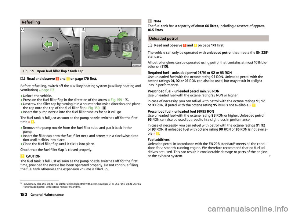
Before refuelling, switch off the auxiliary heating system (auxiliary heating and ventilation) » page 117.
›
Unlock the vehicle.
›
Press on the fuel filler flap in the direction of the arrow » Fig. 159 -
.
›
Unscrew the filler cap by turning it in a counter clockwise direction and place
the cap onto the top of the fuel filler flap » Fig. 159 -
.
›
Insert the pump nozzle into the fuel filler tube as far as it will go.
The fuel tank is full just as soon as the pump nozzle switches off for the first
time »
.
›
Remove the pump nozzle from the fuel filler tube and put it back in the
pump.
›
Insert the filler cap onto the fuel filler neck and screw it in a clockwise direc-
tion until it clicks into place.
›
Close the fuel filler flap until it clicks into place.
Check that the fuel filler flap is closed properly.
CAUTION
The fuel tank is full just as soon as the pump nozzle switches off for the first
time, provided the nozzle has been operated properly. Do not continue filling
the fuel tank otherwise the expansion volume is filled up.NoteThe fuel tank has a capacity of about 60 litres, including a reserve of approx.
10.5 litres .
Unleaded petrol
Read and observe
and on page 179 first.
The vehicle can only be operated with unleaded petrol that meets the EN 2281)
standard.
All petrol engines can be operated using petrol that contains at most 10% bio-
ethanol (E10).
Required fuel - unleaded petrol 95/91 or 92 or 93 RON
Use unleaded fuel with the octane rating 95 RON. Unleaded petrol with the
octane ratings 91, 92 or 93 RON can also be used, but may result in a slight
loss in performance.
Prescribed fuel - unleaded petrol min. 95 RON
Use unleaded fuel with the octane rating 95 RON or higher.
In case of necessity, you can refuel with petrol with the octane ratings 91, 92
or 93 RON, if petrol with the octane rating 95 RON is not available »
.
Prescribed fuel - unleaded fuel 98/95 RON
Use unleaded fuel with the octane rating 98 RON or higher. Unleaded petrol
95 RON can also be used but results in a slight loss in performance.
In case of necessity, you can refuel with petrol with the octane ratings 91, 92
or 93 RON, if unleaded fuel with octane rating 98 RON or 95 RON is not availa-
ble »
.
Fuel additives
Unleaded petrol in accordance with the EN 228 standard 1)
meets all the condi-
tions for a smooth-running engine. We therefore recommend that no fuel ad-
ditives are used. This can result in considerable damage to parts of the engine
or the exhaust system.
1)
In Germany also DIN 51626-1 or E10 for unleaded petrol with octane number 91 or 95 or DIN 51626-2 or E5
for unleaded petrol with octane number 95 and 98.
180General Maintenance
Page 183 of 246
CAUTION■Even filling the tank with leaded petrol that does not meet the standards
once can lead to serious damage to parts of the exhaust system!■
If a fuel other than unleaded fuel which complies to the above mentioned
standards (e.g. leaded petrol) is used by mistake, do not start the engine or
switch on the ignition! Extensive damage to engine parts can occur! We rec-
ommend that you have the fuel system cleaned by a specialist garage.
CAUTION
■ If, in an emergency, the vehicle has to be refuelled with petrol of a lower oc-
tane number than the one prescribed, the journey must only be continued at
medium engine speeds and a low engine load. Driving at high engine revs or a
high engine load can severely damage the engine! Refuel using petrol of the
prescribed octane number as soon as possible.■
Engine parts can be damaged if petrol with a lower octane number than the
one prescribed is used.
■
Even in the event of an emergency, petrol of a lower octane number than 91
RON must not be used, otherwise the engine can be severely damaged!
CAUTION
■ In no case may fuel additives with metal components be used, especially not
with manganese and iron content. LRP(lead replacement petrol) fuels with
metallic components may not be used. There is a risk of causing considerable
damage to parts of the engine or exhaust system!■
Fuels with metallic content may not be used. There is a risk of causing con-
siderable damage to parts of the engine or exhaust system!
Note
■ Unleaded petrol that has a higher octane number than that required by the
engine can be used without limitations.■
On vehicles with prescribed unleaded petrol 95/91, 92 or 93 RON, the use of
petrol with a higher octane number than 95 RON does not result in a noticea-
ble power increase or a lower fuel consumption.
■
On vehicles using prescribed unleaded petrol of min. 95 RON, the use of pet-
rol with a higher octane number than 95 RON can increase the power and re-
duce fuel consumption.
Diesel fuel
Read and observe
and on page 179 first.
The vehicle can only be operated with diesel fuel that meets the EN 5901)
standard.
All diesel engines can be operated using diesel fuel with at most 7% biodiesel
(B7) 2)
.
On the Indian market, your vehicle will only be able to run on diesel fuel com-
pliant with standard IS 1460/Bharat IV. If diesel fuel which complies with this
standard is not available, you can refuel with diesel fuel according to standard
IS 1460/Bharat III in case of emergency.
Operation in winter - Winter-grade diesel fuel
In the cold season, only use “winter-grade diesel fuel” which will still operate properly even at a temperature of -20 °C.
It is often the case in countries with different climatic conditions that diesel
fuels available have a different temperature characteristic. ŠKODA Partners
and filling stations in the relevant country will be able to provide you with in-
formation regarding the diesel fuels available.
Preheating fuel
The vehicle is fitted with a fuel filter preheating system. This secures opera-
tion of a vehicle using diesel fuel down to an environmental temperature of
-25 °C.
Diesel fuel additives
Additives, so-called “flow improvers ” (petrol and similar agents) should not be
mixed with the diesel fuel. This can cause serious damage to engine or ex-
haust system parts.
1)
In Germany also DIN 51628, in Austria ÖNORM C 1590, in Russia GOST R 52368-2005 / EN 590:2004.
2)
In Germany according to the DIN 52638 standard, in Austria ÖNORM C 1590, in France EN 590.
181Inspecting and replenishing
Page 189 of 246
ReplenishingRead and observe
and on page 185 first.
›
Check the oil level » page 186.
›
Unscrew the cap of the engine oil filler opening » Fig. 161 on page 184 .
›
Replenish the oil in portions of 0.5 litres in accordance with the correct speci-
fications » page 185 .
›
Check the oil level » page 186.
›
Carefully screw on the oil filler opening cap and push the dipstick in fully.
Changing
Read and observe
and on page 185 first.
The engine oil must be changed according to prescribed service intervals or ac-
cording to the service interval display » Service plan .
Coolant
Introduction
This chapter contains information on the following subjects:
Capacity
188
Checking the coolant level
188
Replenishing
188
The coolant consists of water with coolant additive. This mixture guarantees
antifreeze protection, protects the cooling/heater system against corrosion
and prevents lime formation.
Vehicles exported to countries with a mild climate are already factory-filled
with a coolant which offers antifreeze protection down to about -25 ℃. In
these countries, the concentration of coolant additive should be at least 40%.
Vehicles exported to countries with a cold climate are already factory-filled
with a coolant which offers antifreeze protection down to about -35 °C. In
these countries, the concentration of coolant additive should be at least 50%.
If a higher concentration of antifreeze is required for climatic reasons, the con-
centration of coolant additive can be increased up to a maximum of 60% (anti-
freeze protection down to approx. -40 °C).
When refilling, only use the same antifreeze identified on the coolant expan-
sion vessel » Fig. 164 on page 188 .WARNING■
The engine compartment of your car is a hazardous area. The following
warning instructions must be followed at all times when working in the en-
gine compartment » page 182.■
Do not continue your journey if for some reason it is not possible to fill
with coolant under the current circumstances
. Switch off the engine and
seek assistance from a specialist garage.
CAUTION
■ The concentration of coolant additive in the coolant must never be under
40%.■
Over 60% of coolant additive in the coolant reduces the antifreeze protec-
tion and cooling effect.
■
A coolant additive that does not comply with the correct specifications can
significantly reduce the corrosion protection.
■
Any faults resulting from corrosion may cause a loss of coolant and can con-
sequently result in major engine damage!
■
Do not fill the coolant above the mark
A
» Fig. 164 on page 188 .
■
If a fault causes the engine to overheat, we recommend visiting a specialist
garage, as otherwise serious engine damage may occur.
■
Additional headlights and other attached components in front of the air inlet
impair the cooling efficiency of the coolant.
■
Never cover the radiator - there is a risk of the engine overheating.
187Inspecting and replenishing
Page 190 of 246
CapacityRead and observe
and on page 187 first.
Coolant capacity (in litres) 1)
Petrol enginesCapacity1.4 ltr./92 kW TSI7.71.8 ltr./112 kW TSI
1.8 ltr./118 kW TSI8.62.0 ltr./147 kW TSI8.63.6 l/191 kW FSI9.0Diesel enginesCapacity1.6 ltr./77 kW TDI CR8.42.0 ltr./103 kW TDI CR8.42.0 ltr./125 kW TDI CR8.4
Checking the coolant level
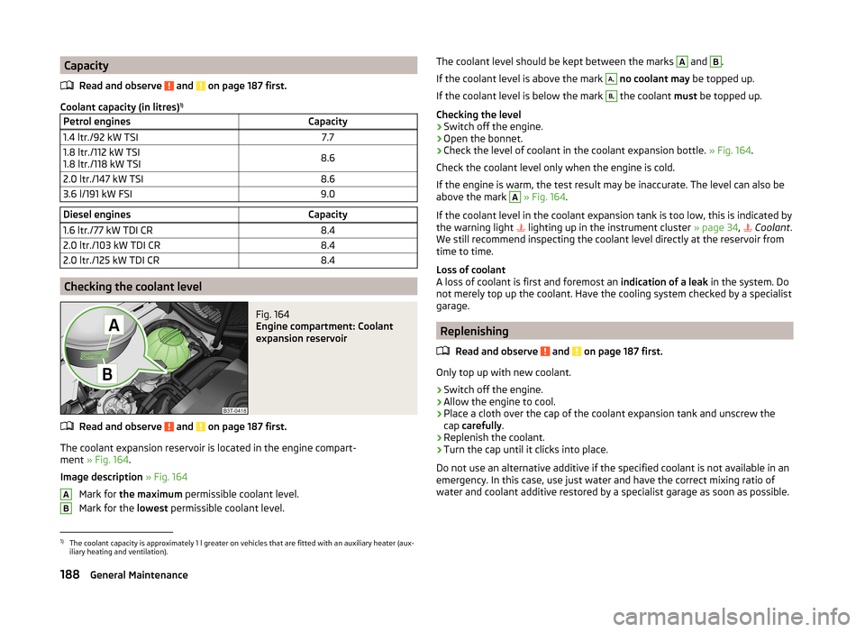
Fig. 164
Engine compartment: Coolant
expansion reservoir
Read and observe and on page 187 first.
The coolant expansion reservoir is located in the engine compart-
ment » Fig. 164 .
Image description » Fig. 164
Mark for the maximum permissible coolant level.
Mark for the lowest permissible coolant level.
ABThe coolant level should be kept between the marks A and B.
If the coolant level is above the mark A,
no coolant may be topped up.
If the coolant level is below the mark
B,
the coolant must be topped up.
Checking the level
›
Switch off the engine.
›
Open the bonnet.
›
Check the level of coolant in the coolant expansion bottle. » Fig. 164.
Check the coolant level only when the engine is cold.
If the engine is warm, the test result may be inaccurate. The level can also be
above the mark
A
» Fig. 164 .
If the coolant level in the coolant expansion tank is too low, this is indicated by
the warning light lighting up in the instrument cluster
» page 34,
Coolant
.
We still recommend inspecting the coolant level directly at the reservoir from
time to time.
Loss of coolant
A loss of coolant is first and foremost an indication of a leak in the system. Do
not merely top up the coolant. Have the cooling system checked by a specialist
garage.
Replenishing
Read and observe
and on page 187 first.
Only top up with new coolant.
›
Switch off the engine.
›
Allow the engine to cool.
›
Place a cloth over the cap of the coolant expansion tank and unscrew the
cap carefully .
›
Replenish the coolant.
›
Turn the cap until it clicks into place.
Do not use an alternative additive if the specified coolant is not available in an
emergency. In this case, use just water and have the correct mixing ratio of
water and coolant additive restored by a specialist garage as soon as possible.
1)
The coolant capacity is approximately 1 l greater on vehicles that are fitted with an auxiliary heater (aux-
iliary heating and ventilation).
188General Maintenance
Page 208 of 246
›Do not remove the foreign body, e.g. screw or nail, from the tyre.›Unscrew the valve cap.›
Use the valve remover
1
to unscrew the valve core and place it on a clean
surface (rag, paper, etc.).
Sealing and inflating the tyre
Read and observe
on page 205 first.
Sealing
›
Shake the tyre inflator bottle
10
» Fig. 181 on page 205 vigorously several
times.
›
Firmly screw the inflation hose
3
onto the tyre inflator bottle
10
in a clock-
wise direction. The film on the cap is pierced automatically.
›
Remove the plug from the inflation hose
3
and plug the open end fully onto
the tyre valve.
›
Hold the bottle
10
with the bottom facing upwards and fill all of the sealing
agent from the tyre inflator bottle into the tyre.
›
Remove the empty tyre inflator bottle from the valve.
›
Screw the valve core back into the tyre valve using the valve remover
1
.
Inflating
›
Screw the air compressor tyre inflation hose
5
» Fig. 181 on page 205 firmly
onto the tyre valve.
›
Check that the air release valve
7
is closed.
›
Start the engine and run it in idle.
›
Plug the connector
9
into 12 Volt socket » page 89, Cigarette lighter .
›
Switch on the air compressor with the ON and OFF switch
8
.
›
Allow the air compressor to run until a pressure of 2.0 - 2.5 bar is achieved.
Maximum run time of 8 minutes »
›
Switch off the air compressor.
›
If you cannot reach an air pressure of 2.0 – 2.5 bar, unscrew the tyre inflation
hose
5
from the tyre valve.
›
Drive the vehicle 10 metres forwards or backwards to allow the sealing agent
to “distribute” in the tyre.
›
Firmly screw the tyre inflation hose
5
back onto the tyre valve and repeat
the inflation process.
›
If you cannot reach the required tyre inflation pressure here either, this
means the tyre has sustained too much damage. You cannot seal with tyre with the breakdown kit »
.
›
Switch off the air compressor.
›
Remove the tyre inflation hose
5
from the tyre valve.
Once a tyre inflation pressure of 2.0 – 2.5 bar is reached, continue the journey
at a maximum speed of 80 km/h (50 mph).
Check the tyre inflation pressure after driving for 10 minutes » page 206.WARNING■
The tyre inflation hose and air compressor may get hot as the tyre is be-
ing inflated – there is a risk of injury.■
Do not place the hot tyre inflation hose or hot air compressor on flamma-
ble materials – there is a risk of fire.
■
If you cannot inflate the tyre to at least 2.0 bar, this means the damage
sustained was too serious. The sealing agent cannot be used to seal the
tyre.
Do not drive the vehicle. Seek help from a specialist garage.
CAUTION
Switch off the air compressor after running 8 minutes at the latest – there is a
risk of overheating. Allow the air compressor to cool a few minutes before
switching it on again.
Check after 10 minutes' driving
Read and observe
on page 205 first.
Check the tyre inflation pressure after driving for 10 minutes!
If the tyre pressure is 1.3 bar or less
›
Do not drive the vehicle! You cannot properly seal with tyre with the
breakdown kit.
If the tyre pressure is 1.3 bar or more
›
Adjust the tyre inflation pressure to the correct value (see inside of fuel filler
cap).
›
Continue driving carefully to the nearest specialist garage at a maximum speed of 80 km/h (50 mph).
206Do-it-yourself
Page 218 of 246
CAUTION■“Never repair” fuses or replace them with a fuse of a higher amperage – risk
of fire! This may also cause damage at another part of the electrical system.■
If a newly inserted fuse blows again after a short time, have the electrical
system checked as quickly as possible by a specialist garage.
■
A blown fuses is recognisable by the molten metal strip. Replace the faulty
fuse with a new one of the same amperage.
Note
■
We recommend always carrying replacement fuses in the vehicle. A box of
replacement fuses can be purchased from ŠKODA Original Accessories.■
There can be several power consuming devices for one fuse.
■
Multiple fuses may exist for a single power consuming device.
Fuses in the dash panel
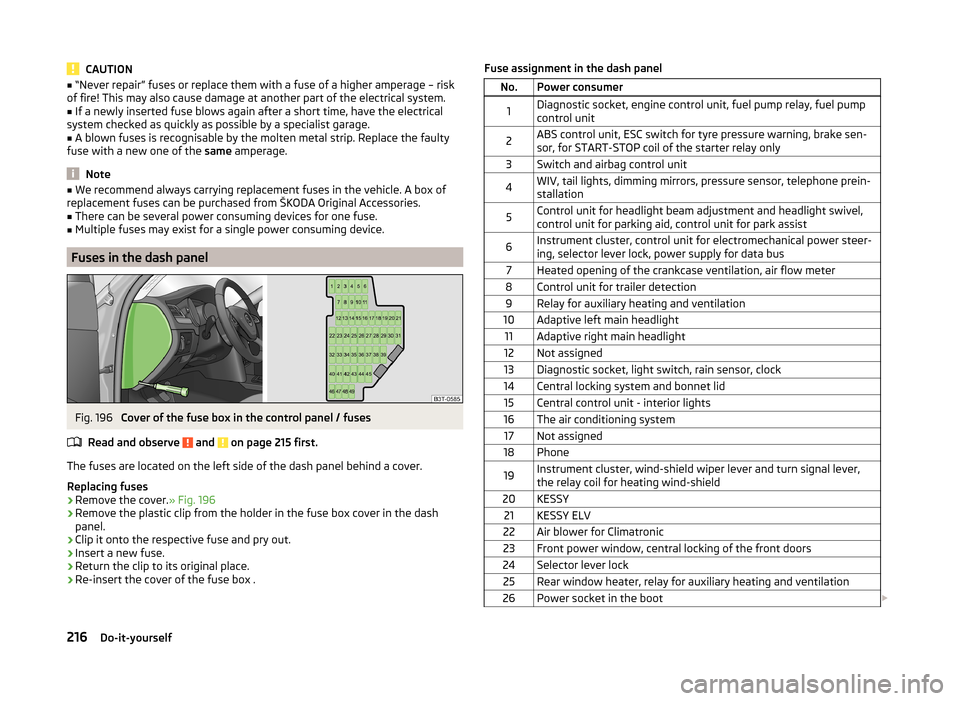
Fig. 196
Cover of the fuse box in the control panel / fuses
Read and observe
and on page 215 first.
The fuses are located on the left side of the dash panel behind a cover.
Replacing fuses
›
Remove the cover. » Fig. 196
›
Remove the plastic clip from the holder in the fuse box cover in the dash
panel.
›
Clip it onto the respective fuse and pry out.
›
Insert a new fuse.
›
Return the clip to its original place.
›
Re-insert the cover of the fuse box .
Fuse assignment in the dash panelNo.Power consumer1Diagnostic socket, engine control unit, fuel pump relay, fuel pump
control unit2ABS control unit, ESC switch for tyre pressure warning, brake sen-
sor, for START-STOP coil of the starter relay only3Switch and airbag control unit4WIV, tail lights, dimming mirrors, pressure sensor, telephone prein-
stallation5Control unit for headlight beam adjustment and headlight swivel,
control unit for parking aid, control unit for park assist6Instrument cluster, control unit for electromechanical power steer-
ing, selector lever lock, power supply for data bus7Heated opening of the crankcase ventilation, air flow meter8Control unit for trailer detection9Relay for auxiliary heating and ventilation10Adaptive left main headlight11Adaptive right main headlight12Not assigned13Diagnostic socket, light switch, rain sensor, clock14Central locking system and bonnet lid15Central control unit - interior lights16The air conditioning system17Not assigned18Phone19Instrument cluster, wind-shield wiper lever and turn signal lever,
the relay coil for heating wind-shield20KESSY21KESSY ELV22Air blower for Climatronic23Front power window, central locking of the front doors24Selector lever lock25Rear window heater, relay for auxiliary heating and ventilation26Power socket in the boot 216Do-it-yourself
Page 219 of 246
No.Power consumer27Fuel pump relay, control unit for fuel pump, injection valves28Electric boot lid29Haldex30Climate controlled front seats31DVD pre-installation32Front power window, central locking system of the rear doors33Electric sliding/tilting roof34Alarm, spare horn35front and rear lighter36Headlight cleaning system37Heated front seats38Heated rear seats39Rear window wiper40Fan air-conditioning system, relay for auxiliary heating and ventila-
tion41Not assigned42Light switch43Control unit for trailer detection44Control unit for trailer detection45Control unit for trailer detection46Switch for seat heating47Telephone preinstallation48Preparation for the aftermarket radio49Only for START-STOP: Central control unit, DC-DC converter, the
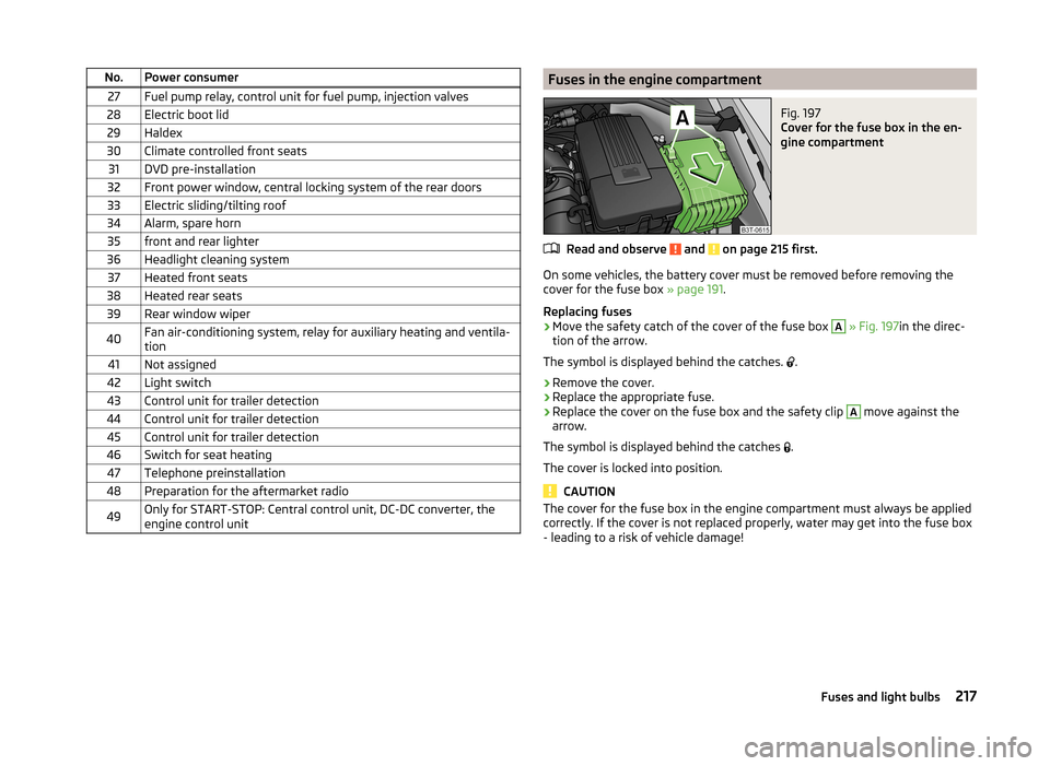
engine control unitFuses in the engine compartmentFig. 197
Cover for the fuse box in the en-
gine compartment
Read and observe and on page 215 first.
On some vehicles, the battery cover must be removed before removing the
cover for the fuse box » page 191.
Replacing fuses
›
Move the safety catch of the cover of the fuse box
A
» Fig. 197 in the direc-
tion of the arrow.
The symbol is displayed behind the catches. .
›
Remove the cover.
›
Replace the appropriate fuse.
›
Replace the cover on the fuse box and the safety clip
A
move against the
arrow.
The symbol is displayed behind the catches .
The cover is locked into position.
CAUTION
The cover for the fuse box in the engine compartment must always be applied
correctly. If the cover is not replaced properly, water may get into the fuse box
- leading to a risk of vehicle damage!217Fuses and light bulbs
Page 220 of 246
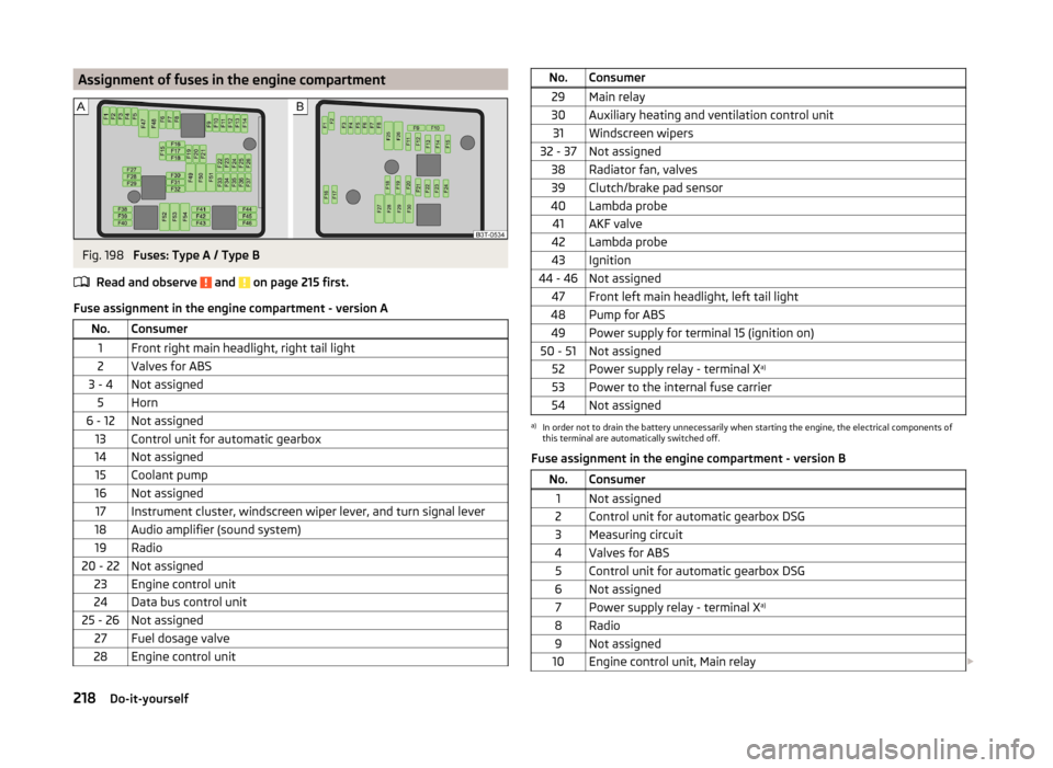
Assignment of fuses in the engine compartmentFig. 198
Fuses: Type A / Type B
Read and observe
and on page 215 first.
Fuse assignment in the engine compartment - version A
No.Consumer1Front right main headlight, right tail light2Valves for ABS3 - 4Not assigned5Horn6 - 12Not assigned13Control unit for automatic gearbox14Not assigned15Coolant pump16Not assigned17Instrument cluster, windscreen wiper lever, and turn signal lever18Audio amplifier (sound system)19Radio20 - 22Not assigned23Engine control unit24Data bus control unit25 - 26Not assigned27Fuel dosage valve28Engine control unitNo.Consumer29Main relay30Auxiliary heating and ventilation control unit31Windscreen wipers32 - 37Not assigned38Radiator fan, valves39Clutch/brake pad sensor40Lambda probe41AKF valve42Lambda probe43Ignition44 - 46Not assigned47Front left main headlight, left tail light48Pump for ABS49Power supply for terminal 15 (ignition on)50 - 51Not assigned52Power supply relay - terminal X a)53Power to the internal fuse carrier54Not assigneda)
In order not to drain the battery unnecessarily when starting the engine, the electrical components of
this terminal are automatically switched off.
Fuse assignment in the engine compartment - version B
No.Consumer1Not assigned2Control unit for automatic gearbox DSG3Measuring circuit4Valves for ABS5Control unit for automatic gearbox DSG6Not assigned7Power supply relay - terminal X a)8Radio9Not assigned10Engine control unit, Main relay
218Do-it-yourself
Page 221 of 246
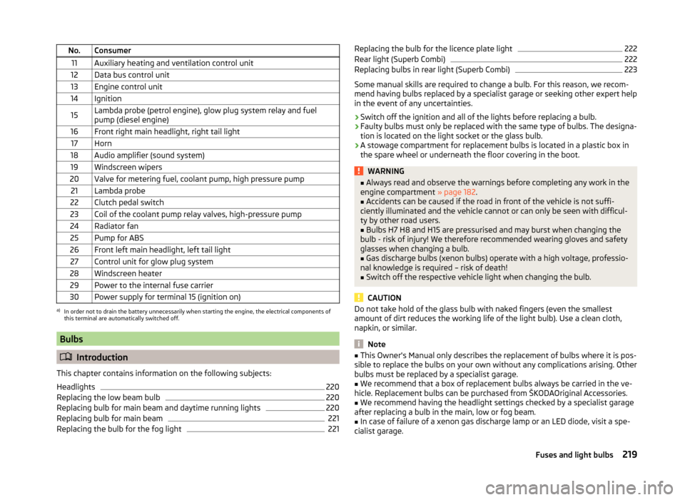
No.Consumer11Auxiliary heating and ventilation control unit12Data bus control unit13Engine control unit14Ignition15Lambda probe (petrol engine), glow plug system relay and fuel
pump (diesel engine)16Front right main headlight, right tail light17Horn18Audio amplifier (sound system)19Windscreen wipers20Valve for metering fuel, coolant pump, high pressure pump21Lambda probe22Clutch pedal switch23Coil of the coolant pump relay valves, high-pressure pump24Radiator fan25Pump for ABS26Front left main headlight, left tail light27Control unit for glow plug system28Windscreen heater29Power to the internal fuse carrier30Power supply for terminal 15 (ignition on)a)
In order not to drain the battery unnecessarily when starting the engine, the electrical components of
this terminal are automatically switched off.
Bulbs
Introduction
This chapter contains information on the following subjects:
Headlights
220
Replacing the low beam bulb
220
Replacing bulb for main beam and daytime running lights
220
Replacing bulb for main beam
221
Replacing the bulb for the fog light
221Replacing the bulb for the licence plate light222Rear light (Superb Combi)222
Replacing bulbs in rear light (Superb Combi)
223
Some manual skills are required to change a bulb. For this reason, we recom-
mend having bulbs replaced by a specialist garage or seeking other expert help
in the event of any uncertainties.
› Switch off the ignition and all of the lights before replacing a bulb.
› Faulty bulbs must only be replaced with the same type of bulbs. The designa-
tion is located on the light socket or the glass bulb.
› A stowage compartment for replacement bulbs is located in a plastic box in
the spare wheel or underneath the floor covering in the boot.
WARNING■ Always read and observe the warnings before completing any work in the
engine compartment » page 182.■
Accidents can be caused if the road in front of the vehicle is not suffi-
ciently illuminated and the vehicle cannot or can only be seen with difficul-
ty by other road users.
■
Bulbs H7 H8 and H15 are pressurised and may burst when changing the
bulb - risk of injury! We therefore recommended wearing gloves and safety
glasses when changing a bulb.
■
Gas discharge bulbs (xenon bulbs) operate with a high voltage, professio-
nal knowledge is required – risk of death!
■
Switch off the respective vehicle light when changing the bulb.
CAUTION
Do not take hold of the glass bulb with naked fingers (even the smallest
amount of dirt reduces the working life of the light bulb). Use a clean cloth,
napkin, or similar.
Note
■ This Owner's Manual only describes the replacement of bulbs where it is pos-
sible to replace the bulbs on your own without any complications arising. Other
bulbs must be replaced by a specialist garage.■
We recommend that a box of replacement bulbs always be carried in the ve-
hicle. Replacement bulbs can be purchased from ŠKODAOriginal Accessories.
■
We recommend having the headlight settings checked by a specialist garage
after replacing a bulb in the main, low or fog beam.
■
In case of failure of a xenon gas discharge lamp or an LED diode, visit a spe-
cialist garage.
219Fuses and light bulbs