clock setting SKODA SUPERB 2014 2.G / (B6/3T) Owner's Manual
[x] Cancel search | Manufacturer: SKODA, Model Year: 2014, Model line: SUPERB, Model: SKODA SUPERB 2014 2.G / (B6/3T)Pages: 246, PDF Size: 17.16 MB
Page 10 of 246

WARNING■Always assume the correct seated position before setting off and do not
change this position while driving. Also advise your passengers to adopt
the correct seated position and not to change this position while the car is
moving.■
Maintain a distance of at least 25 cm from the steering wheel, and a dis-
tance of at least 10 cm between the legs and the dash panel at the height
of the knee airbag. Not maintaining this minimum distance will mean that
the airbag system will not be able to properly protect you - hazard!
■
When driving, hold the steering wheel with both hands firmly on the out-
er edge in the “9 o'clock” and “3 o'clock” position. Never hold the steering
wheel in the “12 o'clock” position or in any other way (e.g. in the middle or
inner edge of the steering wheel). In such cases, you could severely injure
the arms, hands and head when the driver airbag is deployed.
■
Ensure that there are no objects in the driver's footwell as they may get
caught behind the pedals when driving or applying the braking. You would
then no longer be able to operate the clutch, brake or acceleration pedals.
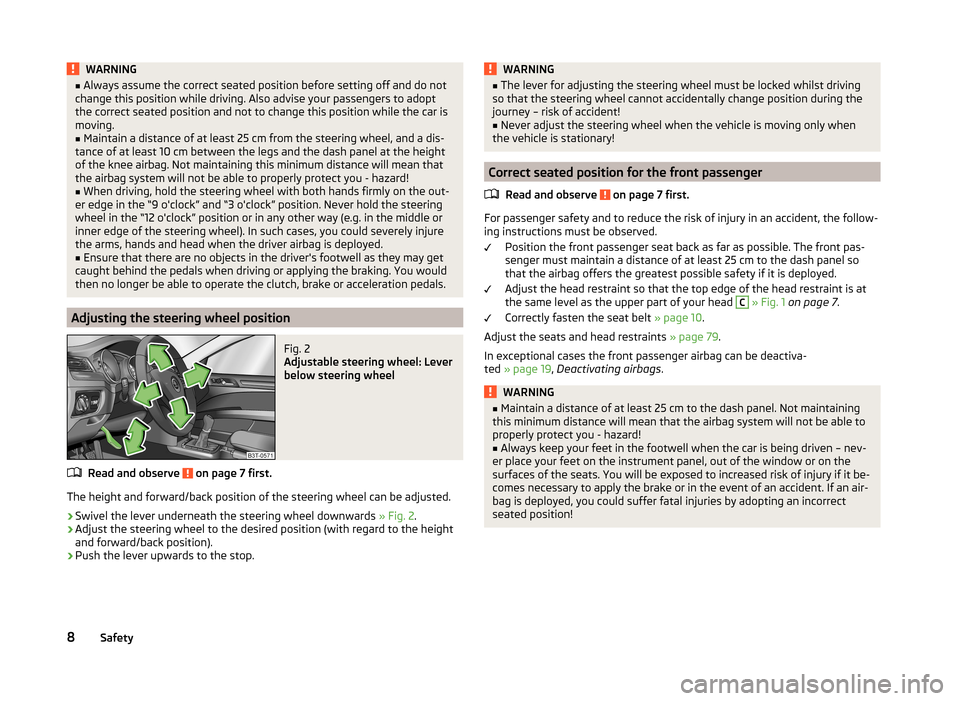
Adjusting the steering wheel position
Fig. 2
Adjustable steering wheel: Lever
below steering wheel
Read and observe on page 7 first.
The height and forward/back position of the steering wheel can be adjusted.
›
Swivel the lever underneath the steering wheel downwards » Fig. 2.
›
Adjust the steering wheel to the desired position (with regard to the height
and forward/back position).
›
Push the lever upwards to the stop.
WARNING■ The lever for adjusting the steering wheel must be locked whilst driving
so that the steering wheel cannot accidentally change position during the
journey – risk of accident!■
Never adjust the steering wheel when the vehicle is moving only when
the vehicle is stationary!
Correct seated position for the front passenger
Read and observe
on page 7 first.
For passenger safety and to reduce the risk of injury in an accident, the follow-ing instructions must be observed.
Position the front passenger seat back as far as possible. The front pas-
senger must maintain a distance of at least 25 cm to the dash panel so
that the airbag offers the greatest possible safety if it is deployed.
Adjust the head restraint so that the top edge of the head restraint is at
the same level as the upper part of your head
C
» Fig. 1 on page 7 .
Correctly fasten the seat belt » page 10.
Adjust the seats and head restraints » page 79.
In exceptional cases the front passenger airbag can be deactiva-
ted » page 19 , Deactivating airbags .
WARNING■
Maintain a distance of at least 25 cm to the dash panel. Not maintaining
this minimum distance will mean that the airbag system will not be able to
properly protect you - hazard!■
Always keep your feet in the footwell when the car is being driven – nev-
er place your feet on the instrument panel, out of the window or on the
surfaces of the seats. You will be exposed to increased risk of injury if it be-
comes necessary to apply the brake or in the event of an accident. If an air-
bag is deployed, you could suffer fatal injuries by adopting an incorrect
seated position!
8Safety
Page 195 of 246

OperationOperating measureSetting the clock» page 30Data in the multifunction display are de-
leted.» page 41
Note
We recommend having the vehicle checked by a specialist garage in order to
ensure full functionality of all electrical systems.
Automatic load deactivation
Read and observe
and on page 190 first.
The vehicle voltage control unit automatically prevents the battery from dis-
charging when the battery is put under high levels of strain. This manifests it-
self by the following.
› The idling speed is raised to allow the generator to deliver more electricity to
the electrical system.
› Where necessary, large convenience consumers such as seat heaters and
rear window heaters have their power limited or are shut off completely in
the event of an emergency.
CAUTION
■ Despite such intervention by the vehicle electric system management, the
vehicle battery may be drained. For example, when the ignition is switched on
a long time with the engine turned off or the side or parking lights are turned
on during longer parking.■
Consumers that are supplied via a 12-V power socket can cause the vehicle
battery to discharge when the ignition is switched off.
Note
Driving comfort is not impaired by consumers being deactivated. The driver is
often not aware of it having taken place.Wheels
Tyres and wheel rims
Introduction
This chapter contains information on the following subjects:
Service life of tyres
194
New tyres
195
Unidirectional tyres
196
Tyre pressure monitor
196
Spare and temporary spare wheel
197
Full wheel trim
198
Wheel bolts
198
Wheel bolts
198WARNINGThe national legal regulations must be observed for the use of tyres.WARNINGInstructions for the use of tyres■For the first 500 km, new tyres do not yet provide optimum grip, and ap-
propriate care should therefore be taken when driving – risk of accident!■
Only use radial tyres of the same type, size (rolling circumference) and
tread pattern on all four wheels.
■
For reasons of driving safety, do not replace tyres individually.
■
Never exceed the maximum permissible load bearing capacity for fitted
tyres – risk of accident!
■
Never exceed the maximum permissible speed for fitted tyres – risk of ac-
cident!
■
Incorrect wheel alignment at the front or rear impairs handling – risk of
accident!
■
Unusual vibrations or pulling of the vehicle to one side could be a sign of
tyre damage. If there is any doubt that a wheel is damaged, immediately re-
duce your speed and stop! If no external damage is evident, drive slowly
and carefully to the nearest specialist garage to have the vehicle checked.
■
Only use tyres or wheel rims that have been approved by ŠKODA for your
model of vehicle. Failure to observe this instruction may impair the road
safety of your vehicle – risk of accident!
193Wheels
Page 199 of 246

›Switch on the ignition.›Press the
» Fig. 170 symbol button for longer than 2 seconds.
If the warning light
in the instrument cluster lights up and does not go out
after the system configuration, this indicates a system fault.
If the warning light
in the instrument cluster flashes, there is a system fault.
Tyre pressure indicator
The warning light
in the instrument cluster lights up when any of the fol-
lowing conditions are met.
› The tyre inflation pressure is low.
› The structure of the tyre is damaged.
› The vehicle is loaded on one side.
› The wheels of one axle are loaded more heavily (e.g. when towing a trailer or
when driving uphill or downhill).
› Snow chains are mounted.
› The spare wheel is mounted.
› One wheel per axle was changed.WARNING■
When the warning light in the instrument cluster lights up, immediate-
ly reduce the speed and avoid sudden steering and brake manoeuvres.
Stop the vehicle as soon as possible and inspect the tyres and their infla-
tion pressure.■
Under certain circumstances (e.g. sporty style of driving, wintry or un-
paved roads) the warning light
in the instrument cluster can be delayed
or does not light up at all.
CAUTION
■ The system cannot warn in case of very rapid tyre inflation pressure loss, e.g.
in case of sudden tyre damage. In this case carefully bring the vehicle to a
standstill without sudden steering movements or sharp braking.■
To ensure a proper functioning of the tyre control display, it is necessary to
repeat the basic setting every 10000 km or once a year.
■
The tyre pressure monitor does not replace the need to check tyre pressure
regularly.
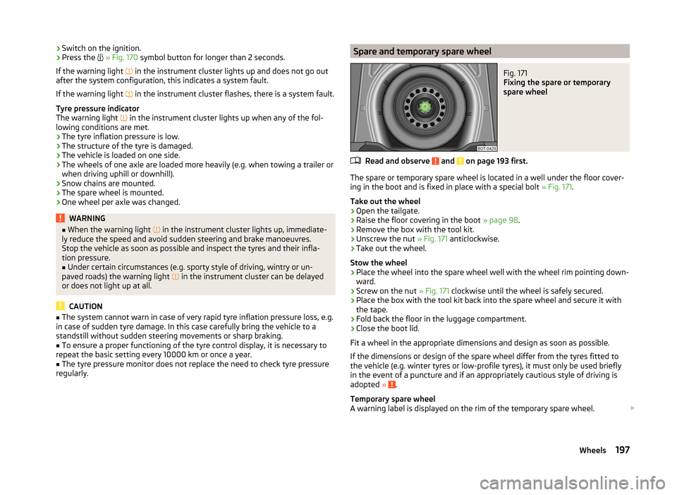
Spare and temporary spare wheelFig. 171
Fixing the spare or temporary
spare wheel
Read and observe and on page 193 first.
The spare or temporary spare wheel is located in a well under the floor cover-
ing in the boot and is fixed in place with a special bolt » Fig. 171.
Take out the wheel
›
Open the tailgate.
›
Raise the floor covering in the boot » page 98.
›
Remove the box with the tool kit.
›
Unscrew the nut » Fig. 171 anticlockwise.
›
Take out the wheel.
Stow the wheel
›
Place the wheel into the spare wheel well with the wheel rim pointing down-
ward.
›
Screw on the nut » Fig. 171 clockwise until the wheel is safely secured.
›
Place the box with the tool kit back into the spare wheel and secure it with
the tape.
›
Fold back the floor in the luggage compartment.
›
Close the boot lid.
Fit a wheel in the appropriate dimensions and design as soon as possible.
If the dimensions or design of the spare wheel differ from the tyres fitted to
the vehicle (e.g. winter tyres or low-profile tyres), it must only be used briefly
in the event of a puncture and if an appropriately cautious style of driving is
adopted »
.
Temporary spare wheel
A warning label is displayed on the rim of the temporary spare wheel.
197Wheels