dimensions SKODA SUPERB 2014 2.G / (B6/3T) Owner's Manual
[x] Cancel search | Manufacturer: SKODA, Model Year: 2014, Model line: SUPERB, Model: SKODA SUPERB 2014 2.G / (B6/3T)Pages: 246, PDF Size: 17.16 MB
Page 199 of 246
›Switch on the ignition.›Press the
» Fig. 170 symbol button for longer than 2 seconds.
If the warning light
in the instrument cluster lights up and does not go out
after the system configuration, this indicates a system fault.
If the warning light
in the instrument cluster flashes, there is a system fault.
Tyre pressure indicator
The warning light
in the instrument cluster lights up when any of the fol-
lowing conditions are met.
› The tyre inflation pressure is low.
› The structure of the tyre is damaged.
› The vehicle is loaded on one side.
› The wheels of one axle are loaded more heavily (e.g. when towing a trailer or
when driving uphill or downhill).
› Snow chains are mounted.
› The spare wheel is mounted.
› One wheel per axle was changed.WARNING■
When the warning light in the instrument cluster lights up, immediate-
ly reduce the speed and avoid sudden steering and brake manoeuvres.
Stop the vehicle as soon as possible and inspect the tyres and their infla-
tion pressure.■
Under certain circumstances (e.g. sporty style of driving, wintry or un-
paved roads) the warning light
in the instrument cluster can be delayed
or does not light up at all.
CAUTION
■ The system cannot warn in case of very rapid tyre inflation pressure loss, e.g.
in case of sudden tyre damage. In this case carefully bring the vehicle to a
standstill without sudden steering movements or sharp braking.■
To ensure a proper functioning of the tyre control display, it is necessary to
repeat the basic setting every 10000 km or once a year.
■
The tyre pressure monitor does not replace the need to check tyre pressure
regularly.
Spare and temporary spare wheelFig. 171
Fixing the spare or temporary
spare wheel
Read and observe and on page 193 first.
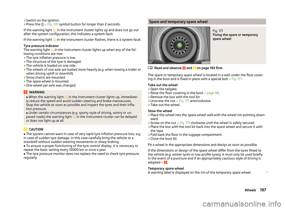
The spare or temporary spare wheel is located in a well under the floor cover-
ing in the boot and is fixed in place with a special bolt » Fig. 171.
Take out the wheel
›
Open the tailgate.
›
Raise the floor covering in the boot » page 98.
›
Remove the box with the tool kit.
›
Unscrew the nut » Fig. 171 anticlockwise.
›
Take out the wheel.
Stow the wheel
›
Place the wheel into the spare wheel well with the wheel rim pointing down-
ward.
›
Screw on the nut » Fig. 171 clockwise until the wheel is safely secured.
›
Place the box with the tool kit back into the spare wheel and secure it with
the tape.
›
Fold back the floor in the luggage compartment.
›
Close the boot lid.
Fit a wheel in the appropriate dimensions and design as soon as possible.
If the dimensions or design of the spare wheel differ from the tyres fitted to
the vehicle (e.g. winter tyres or low-profile tyres), it must only be used briefly
in the event of a puncture and if an appropriately cautious style of driving is
adopted »
.
Temporary spare wheel
A warning label is displayed on the rim of the temporary spare wheel.
197Wheels
Page 200 of 246
Please note the following if you intend to use the temporary spare wheel.› The warning label must not be covered after installing the wheel.
› Be particularly observant when driving.
› The temporary spare wheel is inflated to the maximum inflation pressure for
the vehicle » Fig. 168 on page 194 .
› The tyre inflation pressure of the spare wheel R 18 is 420 kPa.
› Only use this temporary spare wheel to reach the nearest specialist garage,
as it is not intended for long-term use.WARNING■ Never drive with more than one temporary spare wheel mounted!■Never use the temporary spare wheel if it is damaged.■
If the dimensions or design of the temporary spare wheel differ from the
fitted tyres, never drive faster than 80 km/h (or 50 mph).
■
Avoid accelerating at full throttle, sharp braking and fast cornering.
CAUTION
Observe the instructions on the warning sign of the temporary spare wheel.
Full wheel trim
Read and observe
and on page 193 first.
Pulling off
›
Hook the clamp found in the vehicle tool kit » page 201 into the reinforced
edge of the wheel trim.
›
Push the wheel wrench through the clamp, support on the tyre and pull off
the wheel trim.
Fitting
›
Press the wheel trim onto the wheel rim at the designated valve opening.
›
Then press the trim into the wheel rim until its entire circumference locks
correctly in place.
CAUTION
■ Use the pressure of your hand only, do not strike the full wheel trim. Avoid
heavy impacts when the trim has not yet been inserted into the wheel rim.
This could cause damage to the guide and centring elements of the trim.■
When using the anti-theft wheel bolt, ensure that it is in the hole in the
valve area » page 204 , Securing wheels against theft .
■
If wheel trims are retrofitted it must be ensured that an adequate flow of air
is assured to cool the brake system.
Wheel boltsFig. 172
Remove the cap
Read and observe and on page 193 first.
Pulling off
›
Push the extraction pliers » page 201 sufficiently far onto the cap until the
inner catches of the pliers are positioned at the collar of the cap.
›
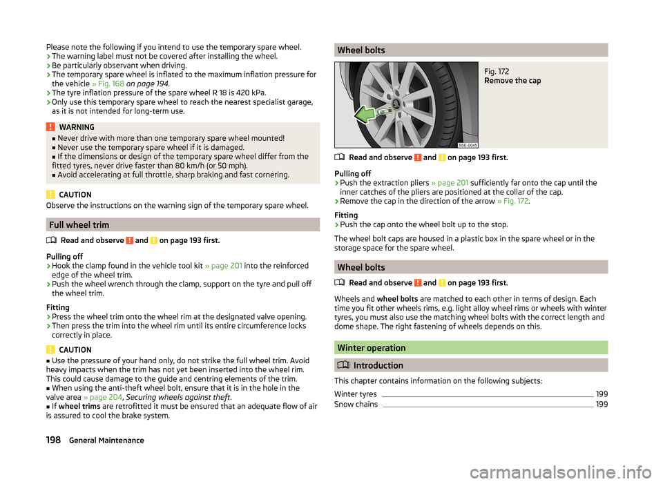
Remove the cap in the direction of the arrow » Fig. 172.
Fitting
›
Push the cap onto the wheel bolt up to the stop.
The wheel bolt caps are housed in a plastic box in the spare wheel or in the
storage space for the spare wheel.
Wheel bolts
Read and observe
and on page 193 first.
Wheels and wheel bolts are matched to each other in terms of design. Each
time you fit other wheels rims, e.g. light alloy wheel rims or wheels with winter
tyres, you must also use the matching wheel bolts with the correct length and
dome shape. The right fastening of wheels depends on this.
Winter operation
Introduction
This chapter contains information on the following subjects:
Winter tyres
199
Snow chains
199198General Maintenance
Page 226 of 246
Technical data
Technical data
Vehicle data
Introduction
This chapter contains information on the following subjects:
Vehicle identification data
224
Operating weight and payload
224
Measurement of fuel consumption and CO 2 emissions according to ECE
Regulations and EU Directives
225
Dimensions
226
Vehicle-specific information depending on engine type
227
Multi-purpose vehicles (AF)
231
The details given in the vehicle's technical documentation always take prece-
dence over the details in the Owner's Manual.
The listed performance values were determined without performance-reduc- ing equipment, e.g. air conditioning system.
Vehicle identification data
Fig. 209
Vehicle data sticker/type plate
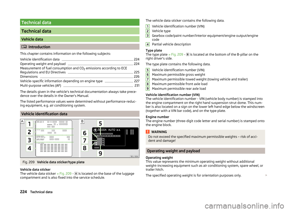
Vehicle data sticker
The vehicle data sticker » Fig. 209 -
is located on the base of the luggage
compartment and is also fixed into the service schedule.
The vehicle data sticker contains the following data.
Vehicle identification number (VIN)
Vehicle type
Gearbox code/paint number/interior equipment/engine output/engine
code
Partial vehicle description
Type plate
The type plate » Fig. 209 -
is located at the bottom of the B-pillar on the
right driver's side.
The type plate contains the following data. Vehicle identification number (VIN)
Maximum permissible gross weight
Maximum permissible towed weight (towing vehicle and trailer)
Maximum permissible front axle load
Maximum permissible rear axle load
Vehicle identification number (VIN)
The vehicle identification number - VIN (vehicle body number) is stamped into
the engine compartment on the right hand suspension strut dome. This num-
ber is also located on a sign on the lower left hand edge below the windscreen
(together with a VIN bar code), and on the type plate.
Engine number
The engine number (three-digit code letter and serial number) is stamped onto
the engine block.WARNINGDo not exceed the specified maximum permissible weights – risk of acci-
dent and damage!
Operating weight and payload
Operating weight
This value represents the minimum operating weight without additional
weight-increasing equipment such as air conditioning system, spare wheel, or
trailer hitch.
The specified operating weight is for orientation purposes only.
123456789224Technical data
Page 228 of 246
Dimensions
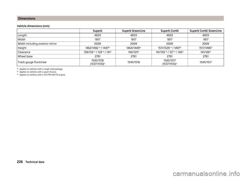
Vehicle dimensions (mm) SuperbSuperb GreenLineSuperb CombiSuperb Combi GreenLineLength4833483348334833Width1817181718171817Width including exterior mirror2009200920092009Height1462/1482 a)
/ 1447 b)1464/1449 b)1511/1529 a)
/ 1497 b)1511/1496 b)Clearance139/159 a)
/ 124 b)
/ 141 c)140/125 b)141/159 a)
/ 127 b)
/ 140 c)141/126 b)Wheel base2761276127612761Track gauge front/rear1545/1518
(1537/1510) c)1545/15181545/1517
(1537/1510) c)1545/1517a)
Applies to vehicles with a rough road package.
b)
Applies to vehicles with a sport chassis.
c)
Applies to vehicles with a 3.6 l/191 kW FSI engine.
226Technical data
Page 243 of 246
Vehicle data sticker224
Vehicle dimensions226
Vehicle height226
Vehicle Identification Number (VIN)224
Vehicle key lock
49
unlock49
Vehicle length226
Vehicle tool kit201
Vehicle width226
Visibility73
Visors see Sun screen
74
see Sun visors74
W
Warning at excessive speeds
43
Warning lights32
warning messages Diesel particulate filter
37
Warning symbols see Warning lights
32
Warning triangle200
Washing169
Automatic car wash system173
by hand172
Chrome parts174
High-pressure cleaner173
Water Driving through
149
Wax treatment See Taking care of your vehicle
174
Weights Maximum permissible weights
224
Wheel bolts Anti-theft wheel bolt
204
Caps198
Loosening and tightening203
Wheel rims193
Wheels Bolts198
Changing201
Full trim198
General information193
Load index196
Replacing wheels194
Service life of tyres194
Snow chains199
Spare wheel197
Speed symbol196
Storing wheels194
Temporary spare wheel197
Tyre pressure194
Tyre sizes194
Tyre wear indicator194
Unidirectional tyres196
Winter tyres199
Wi-Fi127
Windows175
Deicing175
See electric power windows59
Windscreen Deicing
175
Heater73
Windscreen washer fluid Checking
184
Replenishing184
Warning light38
Winter184
Windscreen washers Windscreen washers
76
Windscreen washer system184
Windscreen wiper Replacing the rear window wiper blade
215
Windscreen wipers Operating
76
Replacing the windscreen wiper blades214
Windscreen washer fluid184
Windscreen wipers and washers75
Winter Deicing windows175
Winter operation198
Snow chains199
Winter tyres199
Winter tyres See Wheels
199
WLAN127
MAXI DOT128
Network connection128
Switching off128
Switching on128
241Index
Page 244 of 246
ŠKODA AUTO a.s. pursues a policy of constant product and model develop-
ment. We trust that you will understand that changes to models in terms of
shape, equipment and engineering, may be introduced at any time. The infor-
mation about appearance, performances, dimensions, weight, standards and
functions of the vehicle is correct at the time of publication. Some equipment
might only be introduced at a later date, or might only be offered in certain
markets; information is provided by ŠKODA Partners. It is therefore not possi-
ble for legal claims to be made based on the data, illustrations and descrip-
tions contained in this Owner's Manual.Reprinting, reproduction, translation, or any other use, either in whole or in
part, is not permitted without the written consent of ŠKODA AUTO a.s..
ŠKODA AUTO a.s. expressly reserves all rights relating to copyright laws.
Subject to change.
Issued by: ŠKODA AUTO a.s.
© ŠKODA AUTO a.s. 2014