wheel size SKODA SUPERB 2014 2.G / (B6/3T) Owner's Manual
[x] Cancel search | Manufacturer: SKODA, Model Year: 2014, Model line: SUPERB, Model: SKODA SUPERB 2014 2.G / (B6/3T)Pages: 246, PDF Size: 17.16 MB
Page 9 of 246
›Front side airbags.
› Rear side airbags.
› Head airbags.
› Anchoring points for child seats using the ISOFIX system.
› Anchoring points for child seats using the TOP TETHER system.
› Head restraints adjustable for height.
› Adjustable steering column.
The specified safety equipment works together, in order to optimally protect you and those travelling with you in accident situations.
The safety equipment does not protect you or the people travelling with you, if
you or your occupants adopt an incorrect seated position or the equipment is not correctly adjusted or used.
If the seat belt is not fastened properly, this may result in injuries if an airbag is
activated in the event of an accident.
Correct and safe seated position
Introduction
This chapter contains information on the following subjects:
Correct seated position for the driver
7
Adjusting the steering wheel position
8
Correct seated position for the front passenger
8
Correct seated position for the passengers in the rear seats
9
Examples of incorrect seated positions
9WARNING■ The front seats and all head restraints must be adjusted to match the
body size at all times and the seat belt must always be fastened properly to
provide the most effective levels of protection to the passengers.■
Each occupant must correctly fasten the seat belt belonging to the seat.
Children must be fastened » page 21, Transporting children safely with a
suitable restraint system.
■
If the occupant adopts an incorrect seated position, he is exposed to life-
threatening injuries, in case he is hit by a deployed airbag.
WARNING (Continued)■ If the occupants on the rear seats are not sitting upright, the risk of injury
is increased due to incorrect routing of the seat belt.■
The seat backrests must not be tilted too far back when driving, as this
will impair the function of the seat belts and of the airbag system – risk of
injury!
Correct seated position for the driver
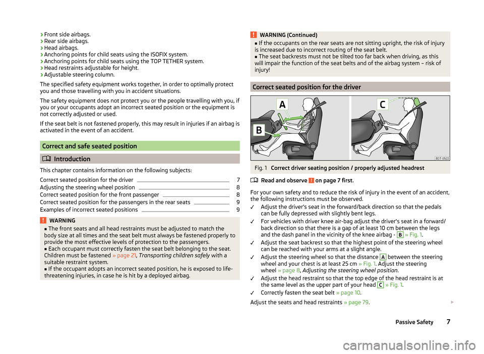
Fig. 1
Correct driver seating position / properly adjusted headrest
Read and observe
on page 7 first.
For your own safety and to reduce the risk of injury in the event of an accident, the following instructions must be observed.
Adjust the driver’s seat in the forward/back direction so that the pedals
can be fully depressed with slightly bent legs.
For vehicles with driver knee air-bag adjust the driver's seat in a forward/
back direction so that there is a gap of at least 10 cm between the legs and the dash panel in the vicinity of the knee airbag -
B
» Fig. 1 .
Adjust the seat backrest so that the highest point of the steering wheel
can be reached with your arms at a slight angle.
Adjust the steering wheel so that the distance
A
between the steering
wheel and your chest is at least 25 cm » Fig. 1. Adjust the steering
wheel » page 8 , Adjusting the steering wheel position .
Adjust the head restraint so that the top edge of the head restraint is at
the same level as the upper part of your head
C
» Fig. 1 .
Correctly fasten the seat belt » page 10.
Adjust the seats and head restraints » page 79.
7Passive Safety
Page 16 of 246
Airbag system
Description of the airbag system
Introduction
This chapter contains information on the following subjects:
System description
14
Airbag deployment
14WARNING■ An airbag can only offer you optimal protection in combination with a
fastened seat belt .■
The airbag is not a substitute for the seat belt, but instead forms part of
the complete passive vehicle safety concept.
■
To ensure passengers are protected with the greatest possible effect
when the airbag is deployed, the front seats must be correctly adjusted to
match the body size » page 7, Correct and safe seated position .
■
If you do not fasten the seat belts when driving, lean too far forward or
adopt an incorrect seated position, you are exposing yourself to increased
risk of injury in the event of an accident.
WARNINGInformation on the use of the airbag system■If there is a fault, the airbag system must be checked by a specialist ga-
rage immediately. Otherwise, there is a risk of the airbag not being activa-
ted in the event of an accident.■
No modifications of any kind must be made to parts of the airbag system.
■
Any work on the airbag system including the installation and removal of
system components due to other repair work (e.g. removal of the steering
wheel) must only be carried out by a specialist garage.
■
Never make any changes to the front bumper or bodywork.
■
It is prohibited to manipulate individual parts of the airbag system as this
might result in the airbag being deployed.
■
The protective function of the airbag system is sufficient for only one ac-
cident. The airbag system must then be replaced if the airbag has been de-
ployed.
System description
Read and observe
on page 14 first.
The functional status of the airbag system is indicated by the indicator light
in the instrument cluster » page 38.
When the airbags are deployed, they fill with gas and inflate.
A grey white or red, non-harmful gas is released when the airbag is inflated.
This is perfectly normal and is not an indication of a fire in the vehicle.
Depending on the vehicle equipment, the airbag system consists of the
following modules.
› Electronic control unit.
› Front airbag for the driver and the front passenger
» page 15.
› Driver’s knee airbag
» page 16.
› Side airbags
» page 17.
› Head airbags
» page 18.
› Airbag warning light in the instrument cluster
» page 38.
› Key switch for the front passenger airbag
» page 20.
› Warning light for the front passenger airbag deactivation/activation in the
middle of the dash panel » page 20.
Note
■
The airbag system needs no maintenance during its working life.■If you sell your vehicle, provide the complete vehicle documentation to the
new owner. Please note that the information relating to the possibility of de-
activating the front passenger airbag must be included!■
When disposing of vehicle or parts of the airbag system, it is important to
comply with the national legal requirements.
Airbag deployment
Read and observe
on page 14 first.
The airbags inflate in fractions of a second and at a high speed in order to be
able to offer additional protection in the event of an accident.
The airbag system is only functional when the ignition is switched on.
In certain accident situations, the several airbags may be deployed simultane-
ously.
14Safety
Page 18 of 246
WARNINGInformation on correct seated position■For the driver and front passenger, it is important to maintain a distance
of at least 25 cm from the steering wheel or dashboard A
» Fig. 9 . Not
maintaining this minimum distance will mean that the airbag system will
not be able to properly protect you - hazard! The front seats and the head
restraints must always also be correctly adjusted to match the body size of
the occupant.
■
The airbag develops enormous forces when triggered, which can lead to
injuries if the sitting position or seated position is not correct.
■
There must not by any further persons, animals or objects positioned be-
tween the front seated occupants and the deployment area of the airbag.
WARNINGFront airbag and transporting children■Never transport children on the front seat of a vehicle without using a
proper restraint system. If airbags are deployed in the event of an accident,
the child might suffer severe or even fatal injuries!■
The front passenger airbag must be deactivated if using a rear-facing
child seat on the front passenger seat » page 19, Deactivating airbags . If
this is not done, there is a risk of the child suffering severe or even fatal
injuries if the front passenger airbag is deployed. When transporting a child
on the front passenger seat, pay attention to any relevant national regula-
tions regarding the use of child safety seats.
WARNINGGeneral information■The steering wheel and the surface of the airbag module in the dash pan-
el on the passenger side must not have stickers attached, be covered or
modified in any other way. These parts should only be cleaned with a cloth
that is dry or has been moistened with water. No objects such as cup hold-
ers, mobile phone mounts, etc. must be attached to the covers of the air-
bag modules or be located within their immediate vicinity.■
Never place objects on the surface of the front passenger airbag module
in the dash panel.
Note■ In vehicles with head airbags, the word AIRBAG can be seen on the steering
wheel.■
In vehicles with front passenger airbags, the word AIRBAG is located on the
dash panel on the passenger side.
Driver’s knee airbag
Fig. 10
Installation of the airbag / Safe distance from the switching panel
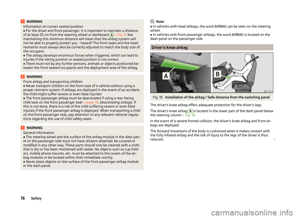
The driver's knee airbag offers adequate protection for the driver's legs.
The driver's knee airbag
A
is located in the lower part of the dash panel below
the steering column » Fig. 10.
In the event of a severe frontal collision, the driver's knee airbag and front air-
bags are deployed.
The forward movement of the body is cushioned when it makes contact with
the fully inflated airbag and the risk of injury to the legs of the driver is thus
reduced.
16Safety
Page 157 of 246
The parking aid is part of the park assist system, therefore the information
and safety guidelines » page 153 , Parking aid must also be read and ob-
served.WARNING■ The system only serves to support and does not relieve the driver of the
responsibility for the vehicle operation.■
During the parking process, the system automatically performs rapid
steering movements. While it is doing so, do not place your hands between
the steering wheel – risk of injury!
■
During a parking manoeuvre on loose or slippery surfaces (gravel, snow,
ice, etc.) you may stray from the calculated road because of the surface
conditions. We therefore recommend not using the system in such situa-
tions.
■
External noise sources may affect the signals of the system sensors. Un-
der adverse conditions, this may cause objects or people to not be recog-
nised by the system.
CAUTION
■ If other vehicles are parked behind or on the kerb, the system can guide your
vehicle beyond the kerb or onto it. Ensure that the wheels or the wheel rims of
your vehicle are not damaged and if necessary intervene in time.■
Under certain circumstances, the surfaces or structures of certain objects
such as wire mesh fences or powder snow cannot be detected by the system.
■
Under adverse weather conditions (heavy rain, water vapour, very low or
high temperatures etc.) system function may be limited.
CAUTION
The correct evaluation of the parking space and the parking procedure de-
pends on the circumference of the wheels on the vehicle.■
The system only works correctly if the vehicle is fitted with the wheel size
approved by the manufacturer.
■
Do without the use of the system if snow chains or a spare wheel is moun-
ted.
■
If wheels other than those approved by the manufacturer are mounted, the
resulting position of the vehicle in the parking space can differ slightly. This
can be avoided by readjusting the system at a specialist garage.
Note
We recommend performing the parking at a safe speed to about 5 km / h.Functioning
Read and observe
and on page 155 first.
Basic system operations
› The measurement and evaluation of the size of parking spaces when driving.
› The determination of the correct position of the vehicle for parking.
› The calculation of the line on which the vehicle drives backwards into the
parking space or forwards from the parking space.
› Automatic rotation of the front wheels during the parking.
The display of the instrument cluster (hereinafter only in the display) informa- tion and system messages are displayed.
When the system is activated, the warning light lights up
» Fig. 148 on
page 155 -
.
The traction control system (TCS) must always be switched on when parking.
Finding a parking space
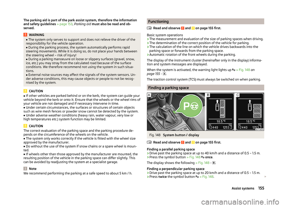
Fig. 148
System button / display
Read and observe
and on page 155 first.
Finding a parallel parking space
›
Drive past the parking space at up to 40 km/h and a distance of 0.5 – 1.5 m.
›
Press the symbol button » Fig. 148
once .
The display shows the following » Fig. 148 -
.
Finding a perpendicular parking space
›
Drive past the parking space at up to 20 km/h and a distance of 0.5 – 1.5 m.
›
Press twice the symbol button
» Fig. 148 .
155Assist systems
Page 195 of 246
OperationOperating measureSetting the clock» page 30Data in the multifunction display are de-
leted.» page 41
Note
We recommend having the vehicle checked by a specialist garage in order to
ensure full functionality of all electrical systems.
Automatic load deactivation
Read and observe
and on page 190 first.
The vehicle voltage control unit automatically prevents the battery from dis-
charging when the battery is put under high levels of strain. This manifests it-
self by the following.
› The idling speed is raised to allow the generator to deliver more electricity to
the electrical system.
› Where necessary, large convenience consumers such as seat heaters and
rear window heaters have their power limited or are shut off completely in
the event of an emergency.
CAUTION
■ Despite such intervention by the vehicle electric system management, the
vehicle battery may be drained. For example, when the ignition is switched on
a long time with the engine turned off or the side or parking lights are turned
on during longer parking.■
Consumers that are supplied via a 12-V power socket can cause the vehicle
battery to discharge when the ignition is switched off.
Note
Driving comfort is not impaired by consumers being deactivated. The driver is
often not aware of it having taken place.Wheels
Tyres and wheel rims
Introduction
This chapter contains information on the following subjects:
Service life of tyres
194
New tyres
195
Unidirectional tyres
196
Tyre pressure monitor
196
Spare and temporary spare wheel
197
Full wheel trim
198
Wheel bolts
198
Wheel bolts
198WARNINGThe national legal regulations must be observed for the use of tyres.WARNINGInstructions for the use of tyres■For the first 500 km, new tyres do not yet provide optimum grip, and ap-
propriate care should therefore be taken when driving – risk of accident!■
Only use radial tyres of the same type, size (rolling circumference) and
tread pattern on all four wheels.
■
For reasons of driving safety, do not replace tyres individually.
■
Never exceed the maximum permissible load bearing capacity for fitted
tyres – risk of accident!
■
Never exceed the maximum permissible speed for fitted tyres – risk of ac-
cident!
■
Incorrect wheel alignment at the front or rear impairs handling – risk of
accident!
■
Unusual vibrations or pulling of the vehicle to one side could be a sign of
tyre damage. If there is any doubt that a wheel is damaged, immediately re-
duce your speed and stop! If no external damage is evident, drive slowly
and carefully to the nearest specialist garage to have the vehicle checked.
■
Only use tyres or wheel rims that have been approved by ŠKODA for your
model of vehicle. Failure to observe this instruction may impair the road
safety of your vehicle – risk of accident!
193Wheels
Page 196 of 246
WARNINGInformation regarding tyre damage or wear■Never use tyres if you do not know anything about the condition and age.■
Never drive with damaged tyres – risk of accident!
■
Immediately replace damaged wheel rims or tyres.
■
You must have your tyres replaced with new ones at the latest when the
wear indicators have been worn down.
■
Worn tyres impair necessary adhesion to the road surface, particularly at
high speeds on wet roads. This could lead to “aquaplaning” (uncontrolled
vehicle movement – “swimming” on a wet road surface).
WARNINGInformation on tyre pressure■The tyre control display does not absolve the driver of the responsibility
to ensure the correct tyre inflation pressure. Check the tyre inflation pres-
sure at regular intervals.■
Insufficient or excessive inflation pressure impairs handling – risk of acci-
dent!
■
If the inflation pressure is too low, the tyre will have to overcome a higher
rolling resistance. This will cause a significant increase in the temperature
of the tyre, especially at higher speeds. This can result in tread separation
and a tyre blowout.
WARNINGInformation on the wheel bolts■The wheel bolts must be clean and must turn easily. Never treat them
with grease or oil.■
The prescribed tightening torque of the wheel bolts for steel and light al-
loy wheels is 120 Nm.
■
If the wheel bolts are tightened to a too low tightening torque, the rims
could come loose when the car is moving – risk of accident! A tightening
torque which is too high can damage the bolts and threads and this can re-
sult in permanent deformation of the contact surfaces on the rims.
■
In case of incorrect treatment of the wheel bolts, the wheel can loosen
when the car is moving – risk of accident!
WARNINGInformation on the temporary spare wheel■Only use the temporary spare wheel when absolutely necessary.■
Never drive with more than one temporary spare wheel mounted.
■
The snow chains cannot be used on the temporary spare wheel.
CAUTION
■ If a spare wheel is used that is not identical to the fitted tyres, the following
must be observed » page 197, Spare and temporary spare wheel .■
Protect the tyres from contact with oil, grease and fuel.
■
Replace lost valve caps.
■
If, in the event of a puncture, it is necessary to fit a spare wheel with a tyre
without a dedicated running direction or with the opposite direction of rota-
tion, drive carefully as the optimal characteristics of the tyre are no longer ap-
plicable in this situation.
For the sake of the environment
Tyres that are insufficiently inflated increase your fuel consumption.
Note
■ We recommend that any work on the wheels or tyres be carried out by a spe-
cialist garage.■
We recommend that you use wheel rims, tyres, full wheel trims and snow
chains from ŠKODA Original Accessories.
Service life of tyres
Fig. 168
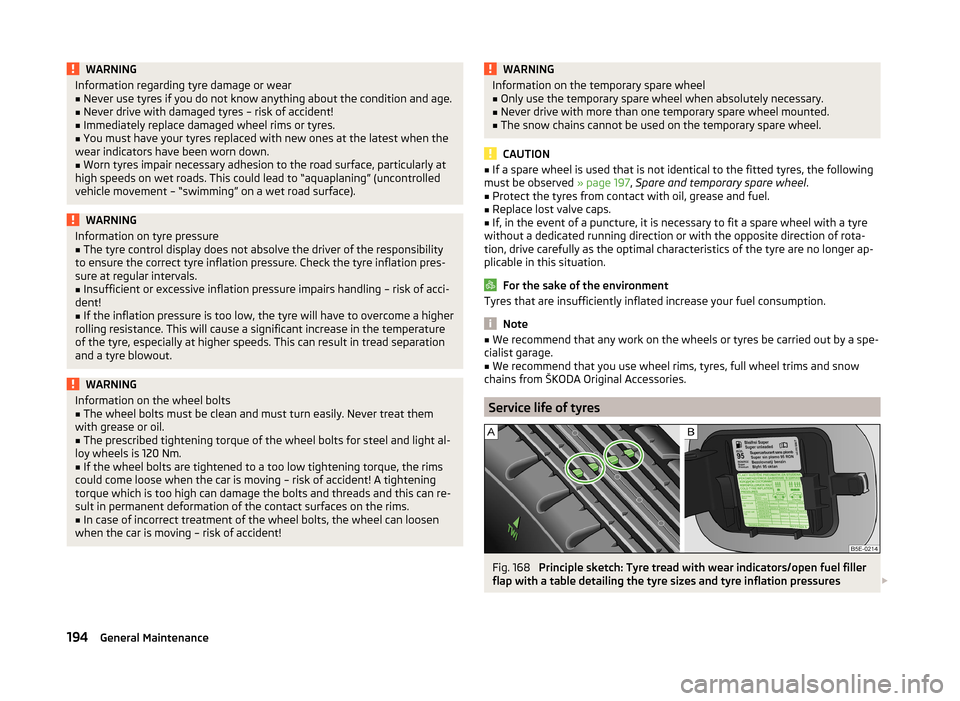
Principle sketch: Tyre tread with wear indicators/open fuel filler
flap with a table detailing the tyre sizes and tyre inflation pressures
194General Maintenance
Page 197 of 246

Fig. 169
Replacing wheels
Read and observe and on page 193 first.
The service life of tyres depends on the inflation pressure, driving style and
other circumstances. Following the advice below can extend the service life of
your tyres.
Tyre pressure
Check the tyre pressure, including that of the spare wheel, at least once a
month and also before setting off on a long journey.
The tyre pressures for tyres are shown on the inside of the fuel filler
flap » Fig. 168 –
.
The tyre pressure should be at the highest pressure specified for your vehicle
at all times.
Always check the inflation pressure when the tyres are cold. Do not reduce the
higher pressure on warm tyres.
With greater additional load, adjust the tyre inflation pressure accordingly.
Driving style
Fast cornering, sharp acceleration and braking increase the wear of your tyres.
Balancing wheels
The wheels of a new vehicle are balanced. When driving, however, there are a
range of factors that may result in an imbalance. This may become apparent by
a “vibration” in the steering.
Have the wheels rebalanced after replacing the tyres.
Wheel alignment errors
Incorrect wheel alignment at the front or rear leads to excess wear of the
tyres.
Tyre damage
Drive over kerbs and other such obstacles slowly and at right angles wherever
possible in order to avoid damage to tyres and wheel trims.
We recommend checking your tyres and wheel rims for damage (punctures,
cuts, splits and bulges, etc.) on a regular basis. Remove foreign bodies (e.g.
small stones) from the tyre tread immediately.
Replacing wheels
If significantly greater wear is present on the front tyres, we recommend
swapping the front wheels with the rear wheels as shown in the dia-
gram » Fig. 169 . You will then obtain approximately the same life for all the
tyres.
We recommend that you swap the tyres every 10,000 km in order to achieve
even wear on all tyres and to ensure optimal service life for the tyres.
Storing tyres
Identify disassembled tyres so that the previous direction of rotation can be
maintained if the tyres are reassembled.
Always store wheels or tyres in a cool, dry place that is as dark as possible.
Tyres which are not fixed to a wheel trim should be stored upright.
Wear indicators
The base of the tread of the tyres has 1.6 mm high wear indicators installed.
These wear indicators are arranged evenly spaced around the circumference of
the tyre a number of times depending on the make » Fig. 168 -
. Markings on
the walls of the tyres through the letters “TWI”, triangular symbols or other
symbols identify the position of the wear indicators.
Tyre age
Tyres age and lose their original characteristics, even if they are not being
used. Therefore, we recommend not using summer or winter tyres older than
6 or 4 years old respectively.
New tyres
Read and observe
and on page 193 first.
Only use radial tyres of the same type, size (rolling circumference) and tread
pattern on one axle on all four wheels.
The tyre/wheel combinations which are approved for your vehicle are indica-
ted in your vehicle documents.
195Wheels
Page 201 of 246
Winter tyres
Fitting winter tyres will significantly improve the handling of your vehicle when
driving in wintry road conditions. Summer tyres have less grip on ice, snow and
at temperatures below 7 °C. This is especially true of vehicles fitted with wide
tyres or high-speed tyres .
In order to achieve the best possible handling properties, winter tyres must be
fitted on all 4 wheels, the minimum tread depth must be 4 mm and tyres must
be no older than 4 years.
Winter tyres of a lower speed category can be used provided that the permissi-
ble maximum speed of these tyres is not exceeded even if the possible maxi-
mum speed of the vehicle is higher.
The speed limit for winter tyres can be set in the MAXI DOT display in the
menu item Winter tyres » page 45 .
For the sake of the environment
Fit the summer tyres on again in good time as they provide better handling
properties, a shorter braking distance, less tyre noise, and reduced tyre wear
on roads which are free of snow and ice as well as at temperatures above 7 °C.
The fuel consumption is also lower.
Snow chains
When driving in wintry road conditions, snow chains improve not only traction,
but also the braking performance.
Snow chains must only be mounted on the front wheels.
For technical reasons, it is only permissible to fit snow chains with the follow-
ing wheel/tyre combinations.
Wheel sizeDepth (D)Tyre size7J x 16 a)45 mm205/556J x 16 a)50 mm205/556J x 1745 mm205/50a)
Not valid for vehicles with 3.6 l/191 kW FSI engine.
Only use fine-link snow chains . They must not project more than 9 mm - in-
cluding the chain lock.
CAUTION■ The chains must be removed when driving on roads which are free of snow.
They adversely affect the handling of your vehicle, damage the tyres and are
rapidly destroyed.■
Remove the full wheel trims » page 198 before fitting the snow chains.
199Wheels
Page 206 of 246
›Insert the crank into the mount on the car jack
» page 201.›Position the lifting jack below the jacking point with the crank and move it up
until its claw is positioned below the vertical web of the lower sill.›
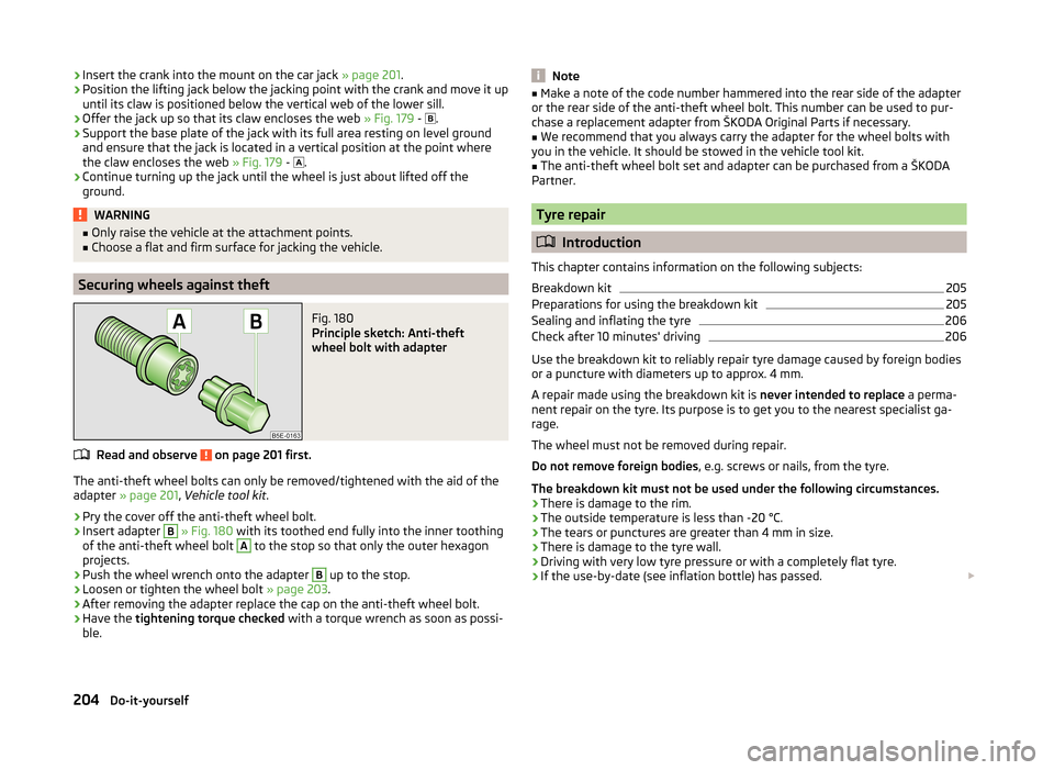
Offer the jack up so that its claw encloses the web » Fig. 179 -
.
›
Support the base plate of the jack with its full area resting on level ground
and ensure that the jack is located in a vertical position at the point where
the claw encloses the web » Fig. 179 -
.
›
Continue turning up the jack until the wheel is just about lifted off the
ground.
WARNING■ Only raise the vehicle at the attachment points.■Choose a flat and firm surface for jacking the vehicle.
Securing wheels against theft
Fig. 180
Principle sketch: Anti-theft
wheel bolt with adapter
Read and observe on page 201 first.
The anti-theft wheel bolts can only be removed/tightened with the aid of the
adapter » page 201 , Vehicle tool kit .
›
Pry the cover off the anti-theft wheel bolt.
›
Insert adapter
B
» Fig. 180 with its toothed end fully into the inner toothing
of the anti-theft wheel bolt
A
to the stop so that only the outer hexagon
projects.
›
Push the wheel wrench onto the adapter
B
up to the stop.
›
Loosen or tighten the wheel bolt » page 203.
›
After removing the adapter replace the cap on the anti-theft wheel bolt.
›
Have the tightening torque checked with a torque wrench as soon as possi-
ble.
Note■ Make a note of the code number hammered into the rear side of the adapter
or the rear side of the anti-theft wheel bolt. This number can be used to pur-
chase a replacement adapter from ŠKODA Original Parts if necessary.■
We recommend that you always carry the adapter for the wheel bolts with
you in the vehicle. It should be stowed in the vehicle tool kit.
■
The anti-theft wheel bolt set and adapter can be purchased from a ŠKODA
Partner.
Tyre repair
Introduction
This chapter contains information on the following subjects:
Breakdown kit
205
Preparations for using the breakdown kit
205
Sealing and inflating the tyre
206
Check after 10 minutes' driving
206
Use the breakdown kit to reliably repair tyre damage caused by foreign bodies
or a puncture with diameters up to approx. 4 mm.
A repair made using the breakdown kit is never intended to replace a perma-
nent repair on the tyre. Its purpose is to get you to the nearest specialist ga-
rage.
The wheel must not be removed during repair.
Do not remove foreign bodies , e.g. screws or nails, from the tyre.
The breakdown kit must not be used under the following circumstances. › There is damage to the rim.
› The outside temperature is less than -20 °C.
› The tears or punctures are greater than 4 mm in size.
› There is damage to the tyre wall.
› Driving with very low tyre pressure or with a completely flat tyre.
› If the use-by-date (see inflation bottle) has passed.
204Do-it-yourself
Page 242 of 246
Door lock cylinders175
Headlight lenses175
High-pressure cleaner173
Plastic parts174
Polishing the paintwork174
Rubber seals174
Taking care of the interior176
Taking care of your vehicle exterior173
Washing172
Washing by hand172
Wash system173
Wax treatment174
Taking care of your vehicles Fabric covers
178
TCS Operation
152
Technical data224
Telephone122, 124
Temporary spare wheel197
Tilting roof see Electric sliding/tilting roof
62
Tiptronic143
Tools201
TOP TETHER24
Towing208
Towing a trailer163
Towing device Description
163
Drawbar load163
Use and care166
Towing eye Front
209
Rear210
Towing protection54
Traction Control System (TCS)152
Trailer163, 166
13-pin power socket167
driving with a trailer167
Loading166
Safety eye167
Trailer stabilisation168
Transport Luggage compartment
95
Roof rack system106
Transporting children safely21
TSA168
Turn signal67
Turn signal system Warning light
38
Twindoor see boot lid
55
Two-way radio systems119
Type plate224
Tyre inflation pressure Warning light
38
Tyre load-bearing capacity See Wheels
196
Tyre pressure monitor Setting
196
Tyre repair Check pressure
206
Preparations205
Sealing and inflating the tyre206
Tyres193
Inflation pressure194
New195
See Wheels195
Sizes194
Tyre wear indicator194
U
Umbrella Tray
93
Underbody protection176
Unleaded petrol150
Unlock Remote control
49
Vehicle key49
Unlocking Individual settings52
KESSY50
Unlocking and locking48
Useful equipment Ashtray
89
Car park ticket holder87
Cigarette lighter89
Clothes hook92
Cup holders88
Glasses storage box91
Removable ski bag95
Seat backrest with long-cargo channel94
Storage compartment in the front centre con- sole
88
Storage compartment on the driver's side87
Storage compartments in the doors88
Using the information system40
Using the selector lever142
V
Variable loading floor
102
Dividing the luggage compartment102
Remove102
slides off on aluminium rails103
Vehicle battery Automatic load deactivation
193
charging192
Checking the battery electrolyte level191
Cover191
Disconnecting and reconnecting192
Operation in winter191
Replace192
Safety instructions189
Vehicle care Alcantara
178
Artificial leather178
Cloths178
Vehicle Condition see Auto Check Control
31
240Index