ABS SKODA SUPERB 2014 2.G / (B6/3T) Owner's Manual
[x] Cancel search | Manufacturer: SKODA, Model Year: 2014, Model line: SUPERB, Model: SKODA SUPERB 2014 2.G / (B6/3T)Pages: 246, PDF Size: 17.16 MB
Page 7 of 246
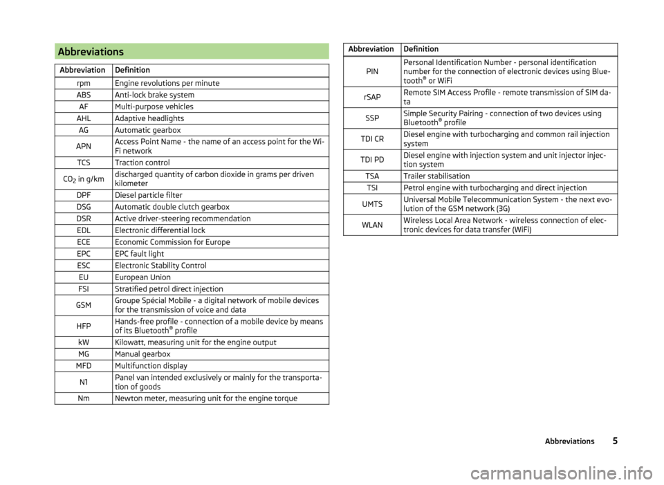
AbbreviationsAbbreviationDefinitionrpmEngine revolutions per minuteABSAnti-lock brake systemAFMulti-purpose vehiclesAHLAdaptive headlightsAGAutomatic gearboxAPNAccess Point Name - the name of an access point for the Wi-
Fi networkTCSTraction controlCO 2 in g/kmdischarged quantity of carbon dioxide in grams per driven
kilometerDPFDiesel particle filterDSGAutomatic double clutch gearboxDSRActive driver-steering recommendationEDLElectronic differential lockECEEconomic Commission for EuropeEPCEPC fault lightESCElectronic Stability ControlEUEuropean UnionFSIStratified petrol direct injectionGSMGroupe Spécial Mobile - a digital network of mobile devices
for the transmission of voice and dataHFPHands-free profile - connection of a mobile device by means
of its Bluetooth ®
profilekWKilowatt, measuring unit for the engine outputMGManual gearboxMFDMultifunction displayN1Panel van intended exclusively or mainly for the transporta-
tion of goodsNmNewton meter, measuring unit for the engine torqueAbbreviationDefinitionPINPersonal Identification Number - personal identification
number for the connection of electronic devices using Blue-
tooth ®
or WiFirSAPRemote SIM Access Profile - remote transmission of SIM da-
taSSPSimple Security Pairing - connection of two devices using
Bluetooth ®
profileTDI CRDiesel engine with turbocharging and common rail injection
systemTDI PDDiesel engine with injection system and unit injector injec-
tion systemTSATrailer stabilisationTSIPetrol engine with turbocharging and direct injectionUMTSUniversal Mobile Telecommunication System - the next evo-
lution of the GSM network (3G)WLANWireless Local Area Network - wireless connection of elec-
tronic devices for data transfer (WiFi)5Abbreviations
Page 12 of 246
Seat belts
Using seat belts
Introduction
Fig. 3
Driver wearing seat belt
This chapter contains information on the following subjects:
The physical principle of a frontal collision
11
Fastening and unfastening seat belts
12
Belt height adjustment on the front seats
13
Seat belts that are fastened correctly offer good protection in the event of an
accident. They reduce the risk of an injury and increase the chance of survival
in the event of a major accident.
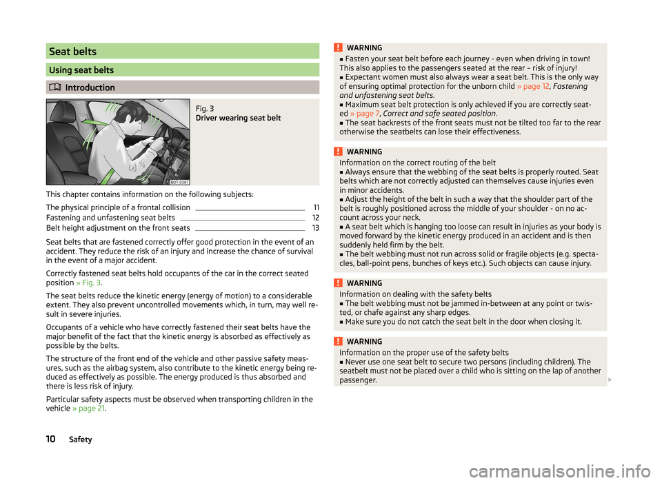
Correctly fastened seat belts hold occupants of the car in the correct seated
position » Fig. 3.
The seat belts reduce the kinetic energy (energy of motion) to a considerable
extent. They also prevent uncontrolled movements which, in turn, may well re-
sult in severe injuries.
Occupants of a vehicle who have correctly fastened their seat belts have the
major benefit of the fact that the kinetic energy is absorbed as effectively as
possible by the belts.
The structure of the front end of the vehicle and other passive safety meas-
ures, such as the airbag system, also contribute to the kinetic energy being re-
duced as effectively as possible. The energy produced is thus absorbed and
there is less risk of injury.
Particular safety aspects must be observed when transporting children in the
vehicle » page 21 .
WARNING■
Fasten your seat belt before each journey - even when driving in town!
This also applies to the passengers seated at the rear – risk of injury!■
Expectant women must also always wear a seat belt. This is the only way
of ensuring optimal protection for the unborn child » page 12, Fastening
and unfastening seat belts .
■
Maximum seat belt protection is only achieved if you are correctly seat-
ed » page 7 , Correct and safe seated position .
■
The seat backrests of the front seats must not be tilted too far to the rear
otherwise the seatbelts can lose their effectiveness.
WARNINGInformation on the correct routing of the belt■Always ensure that the webbing of the seat belts is properly routed. Seat
belts which are not correctly adjusted can themselves cause injuries even
in minor accidents.■
Adjust the height of the belt in such a way that the shoulder part of the
belt is roughly positioned across the middle of your shoulder - on no ac-
count across your neck.
■
A seat belt which is hanging too loose can result in injuries as your body is
moved forward by the kinetic energy produced in an accident and is then
suddenly held firm by the belt.
■
The belt webbing must not run across solid or fragile objects (e.g. specta-
cles, ball-point pens, bunches of keys etc.). Such objects can cause injury.
WARNINGInformation on dealing with the safety belts■The belt webbing must not be jammed in-between at any point or twis-
ted, or chafe against any sharp edges.■
Make sure you do not catch the seat belt in the door when closing it.
WARNINGInformation on the proper use of the safety belts■Never use one seat belt to secure two persons (including children). The
seatbelt must not be placed over a child who is sitting on the lap of another
passenger. 10Safety
Page 13 of 246
WARNING (Continued)■The lock tongue should only be inserted into the lock which is the correct
one for your seat. Wrong use of the safety belt will reduce its capacity to
protect and the risk of injury increases.■
The slot of the belt tongue must not be blocked, otherwise the belt
tongue will not lock in place properly.
■
Many layers of clothing and loose clothing (e. g. a winter coat over a jack-
et) do not allow you to be correctly seated and impairs proper operation of
the seat belts.
■
It is prohibited to use clamps or other objects to adjust seat belts (e. g. for
shortening the belts for smaller persons).
■
The seat belts for the rear seats can only fulfil their function reliably
when the seat backrests are correctly locked into position » page 85.
WARNINGInformation on the care and maintenance of the safety belts■The belt webbing must always be kept clean. Soiled belt webbing may im-
pair proper operation of the inertia reel » page 178.■
The seat belts must not be removed or changed in any way. Do not at-
tempt to repair the seat belts yourself.
■
Check the condition of all the seat belts on a regular basis. If any damage
to the seat belts, seat belt connections, inertia reel or the lock is detected,
the relevant seat belt must be replaced by a specialist garage.
■
Damaged seat belts which have been subjected to stress in an accident
and were therefore stretched, must be replaced – this is best done by a
specialist garage. The anchorage points of the belts must also be inspec-
ted. The anchorage points for the belts should also be checked.
Note
The national legal requirements must be observed when using seat belts.The physical principle of a frontal collisionFig. 4
Driver without a fastened seat belt/rear seat passenger without a
fastened seat belt
Read and observe
on page 10 first.
Motion energy, so-called kinetic energy, is produced as soon as the vehicle is
moving, both for the vehicle and its occupants.
The magnitude of this kinetic energy depends essentially on the speed at
which the vehicle is travelling and on the weight of the vehicle including the
occupants. The greater the speed and weight increase, the greater the
amount of energy which has to be absorbed in the event of an accident.
The speed of the vehicle is the most important factor. Doubling the speed of
the vehicle from 25 km/h up to 50 km/hour increases the kinetic energy four
times.
The idea that it is possible to support your body with your hands in a minor ac-
cident is incorrect. Even in a collision at only a low speed, the forces acting on
the body are such that it is no longer possible to support your body.
Even if you only drive at a speed of 30-50 km/h, the forces that your body is
exposed to in the event of an accident can exceed a metric ton (1000 kg).
For example, a person's weight of 80 kg “increases” to 4.8 tons (4800 kg) at
50 km/h.
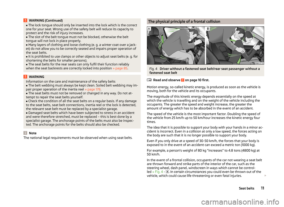
In the event of a frontal collision, occupants of the car not wearing a seat belt
are thrown forward and strike parts of the interior of the car, such as the
steering wheel, dash panel, windscreen in ways which cannot be control-
led » Fig. 4 -
. In certain circumstances you could even be thrown out of the
vehicle, which could cause life threatening or even fatal injuries.
11Seat belts
Page 34 of 246
The following message is shown in the MAXI DOT display.Gearbox overheated. Stop! Log book!
do not continue to drive! Stop the vehicle, switch off the engine, and wait
until the
icon goes out – risk of gearbox damage! You can continue your
journey as soon as the symbol disappears.WARNINGIf you have to stop for technical reasons, then park the vehicle at a safe
distance from the traffic, switch off the engine and activate the hazard
warning lights system » page 70. The warning triangle must be set up at
the prescribed distance - observe the national legal provisions when doing
so.
Note
■ If the MAXI DOT display shows warning messages, these messages must be
confirmed in order to access the main menu » page 40 .■
As long as the operational faults are not rectified, the symbols are always in-
dicated again. After they are displayed for the first time, the symbols continue
to be indicated without any extra messages for the driver.
Warning lights
Introduction
This chapter contains information on the following subjects:
Handbrake
33
Brake system
33
Seat belt warning light
33
Generator
33
Door open
34
Engine oil pressure
34
Coolant
34
Bonnet
34
Boot lid
34
Power steering / steering lock (system KESSY)
34
Engine oil level
35
Traction Control System (ASR)
35
Electronic Stability Control (ESC)
35 Antilock brake system (ABS)36 Rear fog light36
Lamp failure
36
Adaptive headlights (AFS)
36
Exhaust inspection system
36
Glow plug system (diesel engine)
36
Engine performance check (petrol engine)
37
Diesel particulate filter (diesel engine)
37
Fuel reserve
37
Airbag system
38
Tyre inflation pressure
38
Windscreen washer fluid level
38
Pads
38
Turn signal system
38
Low beam
39
Fog lights
39
Cruise control system
39
Selector lever lock / starter (system KESSY)
39
Main beam
39
The warning lights indicate certain functions or faults.
Some warning lights can be accompanied by acoustic signals and messages in
the display of the instrument cluster.
After switching on the ignition, some warning lights illuminate briefly as a
function test.
If the tested systems are OK, the corresponding warning lights go out a few
seconds after switching on the ignition or after starting the engine.
32Operation
Page 35 of 246
WARNING■Ignoring illuminated warning lights and related messages or instructions
in the display of the instrument cluster may lead to serious personal injury
or damage to the vehicle.■
If you have to stop for technical reasons, then park the vehicle at a safe
distance from the traffic, switch off the engine and activate the hazard
warning lights system » page 70. The warning triangle must be set up at
the prescribed distance - observe the national legal provisions when doing
so.
■
The engine compartment of your car is a hazardous area. The following
warning instructions must be followed at all times when working in the en-
gine compartment » page 182, Engine compartment .
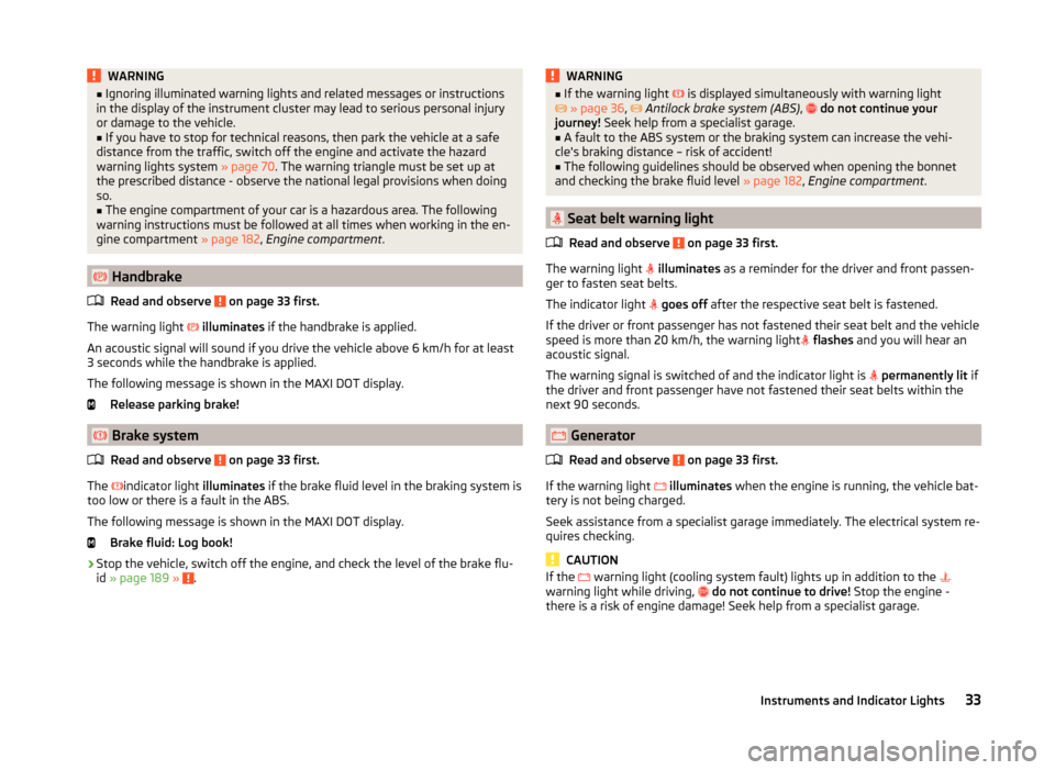
Handbrake
Read and observe
on page 33 first.
The warning light
illuminates if the handbrake is applied.
An acoustic signal will sound if you drive the vehicle above 6 km/h for at least
3 seconds while the handbrake is applied.
The following message is shown in the MAXI DOT display. Release parking brake!
Brake system
Read and observe
on page 33 first.
The indicator light
illuminates if the brake fluid level in the braking system is
too low or there is a fault in the ABS.
The following message is shown in the MAXI DOT display. Brake fluid: Log book!
›
Stop the vehicle, switch off the engine, and check the level of the brake flu-
id » page 189 » .
WARNING■
If the warning light is displayed simultaneously with warning light
» page 36 , Antilock brake system (ABS) , do not continue your
journey! Seek help from a specialist garage.■
A fault to the ABS system or the braking system can increase the vehi-
cle's braking distance – risk of accident!
■
The following guidelines should be observed when opening the bonnet
and checking the brake fluid level » page 182, Engine compartment .
Seat belt warning light
Read and observe
on page 33 first.
The warning light
illuminates as a reminder for the driver and front passen-
ger to fasten seat belts.
The indicator light
goes off after the respective seat belt is fastened.
If the driver or front passenger has not fastened their seat belt and the vehicle
speed is more than 20 km/h, the warning light
flashes and you will hear an
acoustic signal.
The warning signal is switched of and the indicator light is
permanently lit if
the driver and front passenger have not fastened their seat belts within the
next 90 seconds.
Generator
Read and observe
on page 33 first.
If the warning light
illuminates when the engine is running, the vehicle bat-
tery is not being charged.
Seek assistance from a specialist garage immediately. The electrical system re-
quires checking.
CAUTION
If the warning light (cooling system fault) lights up in addition to the
warning light while driving, do not continue to drive! Stop the engine -
there is a risk of engine damage! Seek help from a specialist garage.33Instruments and Indicator Lights
Page 38 of 246
If the warning light illuminates immediately after you start the engine, the
ESC might be switched off due to technical reasons.›
Switch the ignition off and on again.
The ESC is fully functional again if the warning light
no longer illuminates
after you switch the engine back on.
Further information » page 151.
Note
The warning light illuminates after the ignition is switched on if the vehi-
cle's battery has been disconnected and reconnected. If the warning light
does not go out after moving a short distance, this means there is an error in
the system. Seek assistance from a specialist garage immediately.
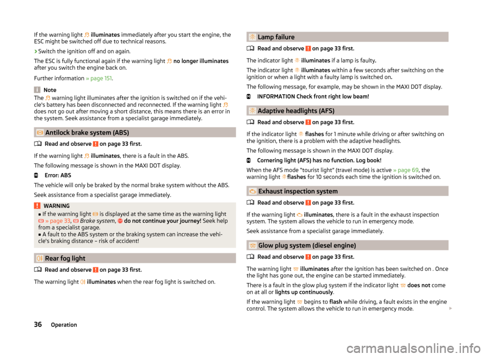
Antilock brake system (ABS)
Read and observe
on page 33 first.
If the warning light
illuminates , there is a fault in the ABS.
The following message is shown in the MAXI DOT display. Error: ABS
The vehicle will only be braked by the normal brake system without the ABS.
Seek assistance from a specialist garage immediately.
WARNING■ If the warning light is displayed at the same time as the warning light
» page 33 , Brake system , do not continue your journey! Seek help
from a specialist garage.■
A fault to the ABS system or the braking system can increase the vehi-
cle's braking distance – risk of accident!
Rear fog light
Read and observe
on page 33 first.
The warning light
illuminates when the rear fog light is switched on.
Lamp failure
Read and observe
on page 33 first.
The indicator light
illuminates if a lamp is faulty .
The indicator light
illuminates within a few seconds after switching on the
ignition or when a light with a faulty lamp is switched on .
The following message, for example, may be shown in the MAXI DOT display. INFORMATION Check front right low beam!
Adaptive headlights (AFS)
Read and observe
on page 33 first.
If the indicator light
flashes for 1 minute while driving or after switching on
the ignition, there is a problem with the adaptive headlights.
The following message is shown in the MAXI DOT display. Cornering light (AFS) has no function. Log book!
When the AFS mode “tourist light” (travel mode) is active » page 69, the
warning light flashes
for 10 seconds each time the ignition is switched on.
Exhaust inspection system
Read and observe
on page 33 first.
If the warning light
illuminates , there is a fault in the exhaust inspection
system. The system allows the vehicle to run in emergency mode.
Seek assistance from a specialist garage immediately.
Glow plug system (diesel engine)
Read and observe
on page 33 first.
The warning light
illuminates after the ignition has been switched on . Once
the light has gone out, the engine can be started immediately.
There is a fault in the glow plug system if the indicator light
does not come
on at all or lights up continuously .
If the warning light begins to
flash while driving, a fault exists in the engine
control. The system allows the vehicle to run in emergency mode.
36Operation
Page 51 of 246
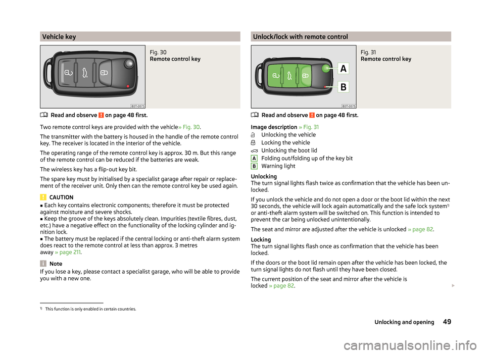
Vehicle keyFig. 30
Remote control key
Read and observe on page 48 first.
Two remote control keys are provided with the vehicle» Fig. 30.
The transmitter with the battery is housed in the handle of the remote control key. The receiver is located in the interior of the vehicle.
The operating range of the remote control key is approx. 30 m. But this range of the remote control can be reduced if the batteries are weak.
The wireless key has a flip-out key bit.
The spare key must by initialised by a specialist garage after repair or replace- ment of the receiver unit. Only then can the remote control key be used again.
CAUTION
■ Each key contains electronic components; therefore it must be protected
against moisture and severe shocks.■
Keep the groove of the keys absolutely clean. Impurities (textile fibres, dust,
etc.) have a negative effect on the functionality of the locking cylinder and ig-
nition lock.
■
The battery must be replaced if the central locking or anti-theft alarm system
does react to the remote control at less than approx. 3 metres
away » page 211 .
Note
If you lose a key, please contact a specialist garage, who will be able to provide
you with a new one.Unlock/lock with remote controlFig. 31
Remote control key
Read and observe on page 48 first.
Image description » Fig. 31
Unlocking the vehicle
Locking the vehicle
Unlocking the boot lid
Folding out/folding up of the key bit
Warning light
Unlocking
The turn signal lights flash twice as confirmation that the vehicle has been un-
locked.
If you unlock the vehicle and do not open a door or the boot lid within the next
30 seconds, the vehicle will lock again automatically and the safe lock system 1)
or anti-theft alarm system will be switched on. This function is intended to prevent the car being unlocked unintentionally.
The seat and mirror are adjusted after the vehicle is unlocked » page 82.
Locking
The turn signal lights flash once as confirmation that the vehicle has been
locked.
If the doors or the boot lid remain open after the vehicle has been locked, the
turn signal lights do not flash until they have been closed.
The current position of the seat and mirror after the vehicle is
locked » page 82 .
AB1)
This function is only enabled in certain countries.
49Unlocking and opening
Page 76 of 246
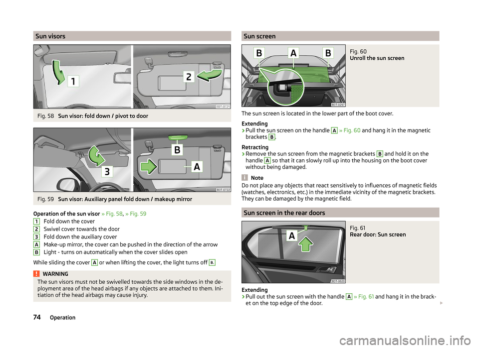
Sun visorsFig. 58
Sun visor: fold down / pivot to door
Fig. 59
Sun visor: Auxiliary panel fold down / makeup mirror
Operation of the sun visor » Fig. 58 , » Fig. 59
Fold down the cover
Swivel cover towards the door
Fold down the auxiliary cover
Make-up mirror, the cover can be pushed in the direction of the arrow
Light - turns on automatically when the cover slides open
While sliding the cover
A
or when lifting the cover, the light turns off
B.WARNINGThe sun visors must not be swivelled towards the side windows in the de-
ployment area of the head airbags if any objects are attached to them. Ini-
tiation of the head airbags may cause injury.123ABSun screenFig. 60
Unroll the sun screen
The sun screen is located in the lower part of the boot cover.
Extending
›
Pull the sun screen on the handle
A
» Fig. 60 and hang it in the magnetic
brackets
B
.
Retracting
›
Remove the sun screen from the magnetic brackets
B
and hold it on the
handle
A
so that it can slowly roll up into the housing on the boot cover
without being damaged.
Note
Do not place any objects that react sensitively to influences of magnetic fields
(watches, electronics, etc.) in the immediate vicinity of the magnetic brackets.
They can be damaged by the magnetic field.
Sun screen in the rear doors
Fig. 61
Rear door: Sun screen
Extending
›
Pull out the sun screen with the handle
A
» Fig. 61 and hang it in the brack-
et on the top edge of the door.
74Operation
Page 153 of 246
Assist systems
Brake assist systems
Introduction
This chapter contains information on the following subjects:
Electronic Stability Control (ESC)
151
Antilock brake system (ABS)
152
Traction Control System (TCS)
152
Electronic Differential Lock (EDL)
152
Driver Steering Recommendation (DSR)
152
Hydraulic Brake Assist (HBA)
152
Hill Hold Control (HHC)
153WARNING■ A lack of fuel can cause irregular engine running or cause the engine to
shut down. The brake assist systems would then fail to function – risk of
accident!■
Adjust the speed and driving style to the current visibility, weather, road
and traffic conditions. The increased safety provided by the brake assist
systems must not tempt you to take safety risks – risk of accident!
■
In the event of an ABS fault, visit a specialist garage immediately. Adjust
your style of driving according to the damage to the ABS, as you will not
know the exact extent of the damage or the extent to which this is limiting the braking efficiency.
CAUTION
■ All four wheels must be fitted with the same tyres approved by the manufac-
turer to ensure the brake assist systems operate correctly.■
Changes to the vehicle (e.g. to the engine, brakes, chassis) can influence the
functionality of the brake assist systems » page 169, Services, modifications,
and technical alterations .
■
If a fault occurs in the ABS system, the ESC, ASR and EDL will also not work.
An ABS fault is indicated by the warning light
» page 36 .
Electronic Stability Control (ESC)Fig. 145
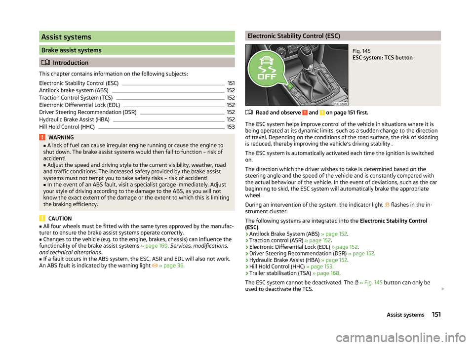
ESC system: TCS button
Read and observe and on page 151 first.
The ESC system helps improve control of the vehicle in situations where it is
being operated at its dynamic limits, such as a sudden change to the direction
of travel. Depending on the conditions of the road surface, the risk of skidding
is reduced, thereby improving the vehicle's driving stability .
The ESC system is automatically activated each time the ignition is switched
on.
The direction which the driver wishes to take is determined based on the
steering angle and the speed of the vehicle and is constantly compared with
the actual behaviour of the vehicle. In the event of deviations, such as the car
beginning to skid, the ESC system will automatically brake the appropriate
wheel.
During an intervention of the system, the indicator light flashes in the in-
strument cluster.
The following systems are integrated into the Electronic Stability Control
(ESC) .
› Antilock Brake System (ABS)
» page 152.
› Traction control (ASR)
» page 152.
› Electronic Differential Lock (EDL)
» page 152.
› Driver Steering Recommendation (DSR)
» page 152.
› Hydraulic Brake Assist (HBA)
» page 152.
› Hill Hold Control (HHC)
» page 153.
› Trailer stabilisation (TSA)
» page 168.
The ESC system cannot be deactivated. The
» Fig. 145 button can only be
used to deactivate the TCS.
151Assist systems
Page 154 of 246
The warning light lights up in the instrument cluster when the ASR is deacti-
vated.
Antilock brake system (ABS)
Read and observe
and on page 151 first.
ABS prevents the wheels locking when braking. Thus helping the driver to
maintain control of the vehicle.
The intervention of the ABS is noticeable from the pulsating movements of
the brake pedal which is accompanied by noises.
When the ABS system is active, do not brake periodically or reduce the pres- sure on the brake pedal.
Traction Control System (TCS)
Fig. 146
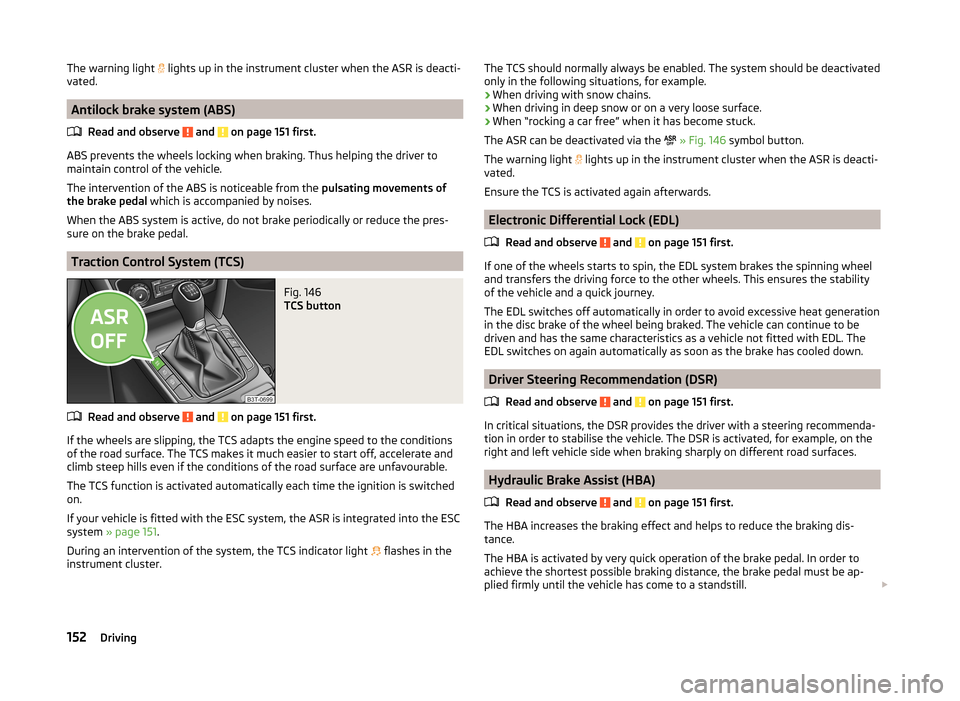
TCS button
Read and observe and on page 151 first.
If the wheels are slipping, the TCS adapts the engine speed to the conditions
of the road surface. The TCS makes it much easier to start off, accelerate and
climb steep hills even if the conditions of the road surface are unfavourable.
The TCS function is activated automatically each time the ignition is switched
on.
If your vehicle is fitted with the ESC system, the ASR is integrated into the ESC
system » page 151 .
During an intervention of the system, the TCS indicator light flashes in the
instrument cluster.
The TCS should normally always be enabled. The system should be deactivated
only in the following situations, for example.
› When driving with snow chains.
› When driving in deep snow or on a very loose surface.
› When “rocking a car free” when it has become stuck.
The ASR can be deactivated via the
» Fig. 146 symbol button.
The warning light
lights up in the instrument cluster when the ASR is deacti-
vated.
Ensure the TCS is activated again afterwards.
Electronic Differential Lock (EDL)
Read and observe
and on page 151 first.
If one of the wheels starts to spin, the EDL system brakes the spinning wheel
and transfers the driving force to the other wheels. This ensures the stability
of the vehicle and a quick journey.
The EDL switches off automatically in order to avoid excessive heat generation
in the disc brake of the wheel being braked. The vehicle can continue to be
driven and has the same characteristics as a vehicle not fitted with EDL. The
EDL switches on again automatically as soon as the brake has cooled down.
Driver Steering Recommendation (DSR)
Read and observe
and on page 151 first.
In critical situations, the DSR provides the driver with a steering recommenda-
tion in order to stabilise the vehicle. The DSR is activated, for example, on the
right and left vehicle side when braking sharply on different road surfaces.
Hydraulic Brake Assist (HBA)
Read and observe
and on page 151 first.
The HBA increases the braking effect and helps to reduce the braking dis-
tance.
The HBA is activated by very quick operation of the brake pedal. In order to
achieve the shortest possible braking distance, the brake pedal must be ap-
plied firmly until the vehicle has come to a standstill.
152Driving