check engine SKODA SUPERB 2015 3.G / (B8/3V) Owner's Guide
[x] Cancel search | Manufacturer: SKODA, Model Year: 2015, Model line: SUPERB, Model: SKODA SUPERB 2015 3.G / (B8/3V)Pages: 276, PDF Size: 42.14 MB
Page 217 of 276
Winter time
The vehicle battery only has a proportion of the starting power in lower tem-
peratures. A discharged vehicle battery may already freeze at temperatures
just below 0 °C .
We therefore recommend that you have the battery checked and, if necessary,
recharged by a specialist garage before the start of the winter.
Note
The battery acid level is also checked regularly by a specialist garage as part of
the inspection service.
Charging
Read and observe
and on page 213 first.
A properly charged vehicle battery is essential for reliably starting the engine.A charging operation can be performed if the following conditions are satis-
fied.
The engine is turned off.
The ignition is switched off.
All consumers are turned off.
The bonnet is open.
“Fast charging” with high currents
›
Disconnect both battery cables (first of all “negative”, then “positive”).
›
Attach the terminal clamps of the charger to the battery terminals (red =
“positive”, black = “negative”).
›
Plug the mains cable of the charger into the power socket and switch on the
device.
›
After charging has been successful: Switch off the charger and remove the
mains cable from the power socket.
›
Only then disconnect the charger's terminal clamps.
›
Reconnect the cables to the battery (first “positive”, then “negative”).
Charging with low voltages
It is not necessary to disconnect the cables from the battery if you recharge
the vehicle battery, for example from a mini-charger.
Refer to the instructions of the charger manufacturer .
A charging current of 0.1 multiple of the total vehicle battery capacity (or low-
er) must be used until full charging is achieved.
The vent plugs of the vehicle battery should not be opened for charging.WARNING■ When you charge a battery, hydrogen is released, and a highly explosive
gas mixture is also produced. An explosion can be caused through sparkling
over during unclamping or loosening of the cable plug while the ignition is
on.■
Creating a bridge between the poles on the battery (e.g. with metal ob-
jects - cables) creates a short circuit - risk of damage to the battery, explo-
sion and burning of the battery, jets of acid spurting out.
■
Avoid creating sparks when working with cables and electrical devices.
Strong sparking represents a risk of injury.
■
Before carrying out any work on the electrical system, switch off the en-
gine, the ignition and all electrical consumers and disconnect the negative
terminal
.
■
“Quick-charging” the vehicle battery is dangerous and requires a special
charger and specialist knowledge.
■
We therefore recommend that vehicle batteries be “rapidly charged” by a
specialist garage.
CAUTION
On vehicles with the START / STOP system or additional heating (auxiliary
heating), do not connect the pole terminal of the charger directly to the nega-
tive terminal of the vehicle battery but only to the engine earth » page 230.
Replacing
Read and observe
and on page 213 first.
The new vehicle battery must have the same capacity, voltage, current and thesame size as the original Battery. Suitable vehicle battery types can be pur-
chased from a specialist garage.
We recommend you have the battery replaced by a specialist garage.
Disconnecting and reconnecting
Read and observe
and on page 213 first.
Disconnecting
›
Switch off the ignition.
215Inspecting and replenishing
Page 218 of 276
›First, disconnect the negative terminal
first, then the positive terminal
of the battery.
Connecting›
First, connect the positive
first, then the negative
battery terminal.
After disconnecting and re-connecting the vehicle battery, the following func-
tions or devices are partially or completely inoperative.
Function / deviceOperating measureElectric window lifters» page 64Panorama sliding/tilting roof» page 65Sun screen» page 66Time setting» page 31
CAUTION
■ Disconnect the vehicle battery only with the ignition turned off - there is a
risk of damaging the electrical system of the vehicle.■
Under no circumstances must the battery cables be connected incorrectly –
risk of a cable fire.
Note
■ After disconnecting and re-connecting the vehicle battery, we recommend
having the vehicle checked by a specialist to ensure that the full functionality
of all electrical systems is guaranteed.■
The data of the multi-function display will be reset.
Automatic load deactivation
Read and observe
and on page 213 first.
The vehicle's electrical system automatically prevents the battery from dis-
charging when the battery is being heavily used. This manifests itself by the
following. ▶ The idling speed is raised to allow the generator to deliver more electricity to
the electrical system.
▶ Where necessary, large convenience consumers such as seat heaters and
rear window heaters have their power limited or are shut off completely in
the event of an emergency.
CAUTION■ Despite such intervention by the vehicle electric system management, the
vehicle battery may be drained. For example, when the ignition is switched on
a long time with the engine turned off or the side or parking lights are turned
on during longer parking.■
Consumers that are supplied via a 12-V power socket can cause the vehicle
battery to discharge when the ignition is switched off.
Note
Driving comfort is not impaired by consumers being deactivated. The driver is
often not aware of it having taken place.216General Maintenance
Page 229 of 276
The mounting points are located on the metal bar » Fig. 246.›
Insert the crank
6
into the mount on the jack
5
» page 223 .
›
Support the base plate of the jack with its full area resting on level ground
and ensure that the jack is located in a vertical position at the jacking point
» Fig. 247 -
.
›
Position the lifting jack below the jacking point with the crank and move it up
until its claw encloses the web » Fig. 247 -
.
›
Continue turning up the jack until the wheel is just about lifted off the
ground.
WARNING■ If the wheel has to be changed on a slope, first of all block the opposite
wheel with a stone or similar object to prevent the vehicle from unexpect-
edly rolling away.■
Secure the base plate of the lifting jack with suitable means to prevent
possible moving. A soft and slippery ground under the base plate may move
the lifting jack, causing the vehicle to fall down. It is therefore always nec-
essary to place the lifting jack on a solid surface or use a wide and stable
base. Use a non-slip base (e.g. a rubber foot mat) if the surface is smooth,
such as cobbled stones, tiled floor, etc.
■
Only attach the lifting jack to the attachment points provided for this pur-
pose.
■
Always raise the vehicle with the doors closed.
■
Never position any body parts, such as arms or legs under the vehicle,
while the vehicle is raised with a lifting jack.
■
When the vehicle is raised, never start the engine.
CAUTION
It is important to ensure that the jack is correctly attached to the web of the
lower fork leg - risk of damage to the vehicle.
Remove the wheel / fix
When changing a wheel, the following instructions must be followed.
›
Remove the full wheel trim or the caps of the wheel bolts.
›
First of all slacken the anti-theft wheel bolt and then the other wheel bolts.
›
Jack up the vehicle until the wheel that needs changing is clear of the
ground.
›
Unscrew the wheel bolts and place them on a clean surface (cloth, paper,
etc.).
› Remove the wheel carefully.›Attach the wheel and slightly screw on the wheel bolts.›
Lower the vehicle.
›
Tighten the wheel bolts opposite each other using the wheel wrench (alter-
nating crosswise). Tighten the anti-theft wheel bolt last.
›
Replace the wheel trim or the caps.
When fitting unidirectional tyres, ensure that the direction of rotation is cor-
rect » page 219 .
All bolts must be clean and must turn easily.
If it is established when changing a wheel that the wheel bolts are corroded and difficult to move, then these must be replaced.
Under no circumstances grease or oil the wheel bolts!
WARNINGUndo the wheel bolts only a little (about one turn) as long as the vehicle
has not yet been jacked up. Otherwise the wheel could become loose and
fall off.
Follow-up tasks
After changing the wheel, the following work must be carried out.
›
Stow the replaced wheel in the wheel well and secure it with a special screw.
›
Stow the tool kit in the space provided and secure using the band.
›
Check the tyre pressure on the installed wheel as soon as possible.
›
Have the tightening torque of the wheel bolts checked with a torque wrench
as soon as possible.
After changing the wheel, the tyre pressure should be adjusted. In vehicles
with tyre pressure monitoring, save tyre pressure values » page 183.
Replace the damaged wheel or consult a specialist garage about repair op-
tions.
The prescribed tightening torque of the wheel bolts is 140 Nm.
227Emergency equipment and self-help
Page 231 of 276
General informationRead and observe
on page 228 first.
For your own safety and the safety of your passengers, the following instruc-
tions must be observed before carrying out a wheel repair on the road.
Switch on the hazard warning lights system.
Place the warning triangle at the prescribed distance.
Park the vehicle as far away as possible from the flowing traffic.
Choose a location with a flat, solid surface.
Have all the occupants get out. The passengers should not stand on the
road (instead they should remain behind a crash barrier, for instance) while
the wheel is being changed.
The breakdown kit must not be used under the following circumstances. ▶ The rim is damaged.
▶ The outside temperature is below -20 ° C.
▶ The cut or puncture is larger than 4 mm.
▶ The tyre wall is damaged.
▶ After the expiration date (see inflation bottle).
Preparations for using the breakdown kit
Read and observe
on page 228 first.
The following preparatory work must be carried out before using the puncturerepair kit.
›
Switch off the engine.
›
For vehicles with manual transmission engage 1st gear.
›
On vehicles with
automatic transmission place the selector lever in the P po-
sition.
›
The parking brake switch.
›
Check that you can carry out the repairs with the breakdown kit » page 228.
›
Uncouple any trailers.
›
Remove the breakdown kit from the boot.
›
Stick the sticker
1
» Fig. 248 on page 228 on the dashboard in the driver's
field of view.
›
Unscrew the valve cap.
›
Use the valve remover
2
to unscrew the valve core and place it on a clean
surface (rag, paper, etc.).
Sealing and inflating the tyre
Read and observe
on page 228 first.
Sealing
›
Forcefully shake the tyre inflation bottle
10
» Fig. 248 on page 228 back and
forth several times.
›
Firmly screw the inflation hose
3
onto the tyre inflater bottle
10
. The film on
the cap is pierced automatically.
›
Remove the plug from the inflation hose
3
and plug the open end fully onto
the tyre valve.
›
Hold the bottle
10
with the bottom facing upwards and fill all of the sealing
agent from the tyre inflator bottle into the tyre.
›
Remove the filler plug from the tyre valve.
›
Screw the valve core back into the tyre valve using the valve remover
2
.
Inflating
›
Screw the air compressor tyre inflation hose
7
» Fig. 248 on page 228 firmly
onto the tyre valve.
›
For vehicles with manual transmission the lever into the neutral position.
›
On vehicles with automatic transmission place the selector lever in the P po-
sition.
›
Start the engine and run it in idle.
›
Plug the connector
6
into 12 volt socket » page 100.
›
Switch on the air compressor with the ON and OFF switch
9
.
›
Allow the air compressor to run until a pressure of 2.0 - 2.5 bar is achieved.
Maximum run time of 8 minutes » .
›
Switch off the air compressor.
›
If you cannot reach an air pressure of 2.0 - 2.5 bar, unscrew the tyre inflation
hose
7
from the tyre valve.
›
Drive the vehicle 10 metres forwards or backwards to allow the sealing agent
to “distribute” in the tyre.
›
Firmly screw the tyre inflation hose
7
back onto the tyre valve and repeat
the inflation process.
›
Switch off the air compressor.
›
Remove the tyre inflation hose
7
from the tyre valve.
Once a tyre inflation pressure of 2.0 - 2.5 bar is achieved, you can continue the journey.
229Emergency equipment and self-help
Page 240 of 276
›Turn on the ignition and press the lever into position 4
» page 78 , Wind-
screen wipers and washers .
Move the windscreen wiper arms into the home position.
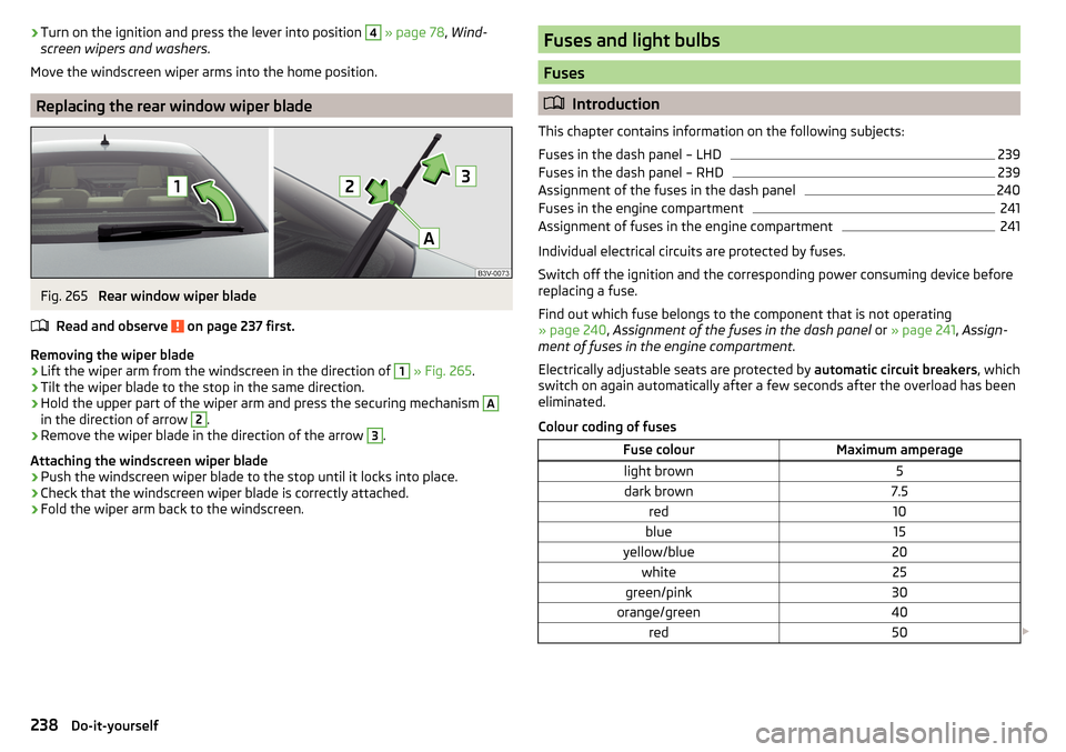
Replacing the rear window wiper blade
Fig. 265
Rear window wiper blade
Read and observe
on page 237 first.
Removing the wiper blade
›
Lift the wiper arm from the windscreen in the direction of
1
» Fig. 265 .
›
Tilt the wiper blade to the stop in the same direction.
›
Hold the upper part of the wiper arm and press the securing mechanism
A
in the direction of arrow
2
.
›
Remove the wiper blade in the direction of the arrow
3
.
Attaching the windscreen wiper blade
›
Push the windscreen wiper blade to the stop until it locks into place.
›
Check that the windscreen wiper blade is correctly attached.
›
Fold the wiper arm back to the windscreen.
Fuses and light bulbs
Fuses
Introduction
This chapter contains information on the following subjects:
Fuses in the dash panel – LHD
239
Fuses in the dash panel – RHD
239
Assignment of the fuses in the dash panel
240
Fuses in the engine compartment
241
Assignment of fuses in the engine compartment
241
Individual electrical circuits are protected by fuses.
Switch off the ignition and the corresponding power consuming device before
replacing a fuse.
Find out which fuse belongs to the component that is not operating
» page 240 , Assignment of the fuses in the dash panel or » page 241 , Assign-
ment of fuses in the engine compartment .
Electrically adjustable seats are protected by automatic circuit breakers, which
switch on again automatically after a few seconds after the overload has been
eliminated.
Colour coding of fuses
Fuse colourMaximum amperagelight brown5dark brown7.5red10blue15yellow/blue20white25green/pink30orange/green40red50 238Do-it-yourself
Page 241 of 276
WARNINGAlways read and observe the warnings before completing any work in the
engine compartment » page 206.
CAUTION
■
“Never repair” fuses, and do not replace them with fuses of a higher amper-
age – risk of fire! This may also cause damage at another part of the electrical
system.■
If a newly inserted fuse blows again after a short time, have the electrical
system checked as quickly as possible by a specialist garage.
■
A blown fuses is recognisable by the molten metal strip. Replace the faulty
fuse with a new one of the same amperage.
Note
■
We recommend always carrying replacement fuses in the vehicle. A box of
replacement fuses and bulbs can be purchased from ŠKODA Genuine Accesso-
ries.■
There can be several power consuming devices for one fuse.
■
Multiple fuses may exist for a single power consuming device.
Fuses in the dash panel – LHD
Fig. 266
Storage compartment on the
driver's side
Read and observe and on page 239 first.
On left-hand drive vehicles, the fuse box is located behind the storage com- partment in the left-hand section of the dash panel.
Replacing fuses
›
Open the storage compartment » page 91.
›
Grab hold of the storage compartment in the area of the arrows » Fig. 266.
›
Fold out the storage compartment by pulling in the direction of arrow
1
.
›Remove the plastic clip under the cover of the fuse box in the engine room
» Fig. 269 on page 241 .›
Place the clip on the respective fuse and pull this fuse out.
›
Insert a new fuse.
›
Replace the bracket at the original position.
›
Fold back the storage compartment by pressing into the secured position in
the dash panel in the direction of the arrow
2
.
›
Close the storage compartment.
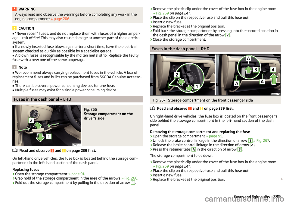
Fuses in the dash panel – RHD
Fig. 267
Storage compartment on the front passenger side
Read and observe
and on page 239 first.
On right-hand drive vehicles, the fuse box is located on the front passenger's side behind the stowage compartment in the left-hand section of the dash
panel.
Removing the storage compartment and replacing the fuse
›
Open the storage compartment » page 95.
›
Unlock the brake control linkage in the direction of arrow
1
» Fig. 267 .
›
Release the brake control linkage in the direction of arrow
2
.
›
Press the retainer tabs
A
in the direction of arrow
3
.
The storage compartment folds down.
›
Remove the plastic clip under the cover of the fuse box in the engine room
» Fig. 269 on page 241 .
›
Place the clip on the respective fuse and pull this fuse out.
›
Insert a new fuse.
›
Replace the bracket at the original position.
239Fuses and light bulbs
Page 244 of 276
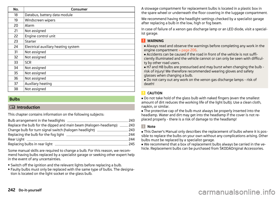
No.Consumer18Databus, battery data module19Windscreen wipers20Alarm21Not assigned22Engine control unit23Starter24Electrical auxiliary heating system31Not assigned32Not assigned33SCR34Not assigned35Not assigned36Not assigned37Auxiliary heating38Not assigned
Bulbs
Introduction
This chapter contains information on the following subjects:
Bulb arrangement in the headlights
243
Replace the bulb for the dipped and main beam (Halogen-headlamp)
243
Change bulb for turn signal switch (halogen headlight)
243
Replacing the bulb for the fog light
244
Rear Light
244
Replacing bulbs in rear light
245
Some manual skills are required to change a bulb. For this reason, we recom-
mend having bulbs replaced by a specialist garage or seeking other expert help
in the event of any uncertainties.
▶ Switch off the ignition and the relevant lights before replacing a bulb.
▶ Faulty bulbs must only be replaced with the same type of bulbs. The designa-
tion is located on the light socket or the glass bulb.
A stowage compartment for replacement bulbs is located in a plastic box in
the spare wheel or underneath the floor covering in the luggage compartment.
We recommend having the headlight settings checked by a specialist garage
after replacing a bulb in the low, high or fog beam.
In case of failure of a xenon gas discharge lamp or an LED diode, visit a special- ist garage.WARNING■ Always read and observe the warnings before completing any work in the
engine compartment » page 206.■
Accidents can be caused if the road in front of the vehicle is not suffi-
ciently illuminated and the vehicle cannot or can only be seen with difficul-
ty by other road users.
■
H7 and H8 bulbs are pressurised and may burst when changing the bulb -
risk of injury! We therefore recommended wearing gloves and safety
glasses when changing a bulb.
■
Do not carry out any work on the xenon gas discharge lamps - risk of
death!
CAUTION
■ Do not take hold of the glass bulb with naked fingers (even the smallest
amount of dirt reduces the working life of the light bulb). Use a clean cloth,
napkin, or similar.■
The protective cap of the bulb must always be properly inserted into the
headlamp. Water and dirt may get into the headlamp if the cover is not re-
placed properly - there is a risk of damage to the headlamp!
Note
■ This Owner's Manual only describes the replacement of bulbs where it is pos-
sible to replace the bulbs on your own without any complications arising. Other
bulbs must be replaced by a specialist garage.■
We recommend that a box of replacement bulbs always be carried in the ve-
hicle. Replacement bulbs can be purchased from ŠKODAOriginal Accessories.
242Do-it-yourself
Page 259 of 276
automatic transmissionselector lever lock defect137
Automatic transmission135
Kick down138
Launch control138
Malfunctions37
Selector lever lock137
Warning light37
Warning messages37
AUX99
Auxiliary heating (auxiliary heating and ventila- tion)
123
Adjust124
Switching on/off124
Auxiliary heating (heating and ventilation) Radio remote control
125
Avoiding damage to your vehicle141
B
Bags on the backs of the front seats
97
on the inner sides of the front seats97
Battery In the remote control key
234
Replace the KESSY key234
Belts11
Belt tensioners14
Bonnet Closing
207
Opening207
Boot Class N1 vehicles
114
Non-contact opening61
See Boot lid59
Boot lid automatic locking
59
Closing59
Non-contact opening61
Opening59
Brake Information messages33
Warning light33
Brake Assist (HBA)145
Brake booster133
brake fluid specification
213
Brake fluid212
Checking212
Information messages33
Brake linings Warning light
36
Brake pedal (automatic transmission) Warning light
37
Brakes Brake booster
133
Brake fluid212
Braking and stabilisation systems143
Running-in139
Brakes and parking132
Brake system143
Braking Information on braking
132
Bulbs Replacing
242
C
Camera Lens care
197
Camera lens care
197
Car care Jack
197
Car computer see multifunction display
42
Care and maintenance190
Cargo element112
Car park134
Car park ticket holder91
Carrier Roof rack117
Cavity protection197
Central locking52
Problems57
Central locking button55
Change Bulb for indicator (halogen headlight)
243
engine oil209
light bulb in tail light244
Change engine oil
209
Changing Wheels
224
Changing a wheel Follow-up tasks
227
Preparation224
Changing wheels Wheel removal and fix
227
Charging a vehicle battery215
Checking Battery electrolyte level
214
Brake fluid212
Coolant211
Engine oil210
Oil level210
Windscreen washer fluid208
Checks Statutory checks
190
Children and safety20
Child safety Side airbag
22
Child safety lock57
Child safety seat Use of child safety seats
23
Child seat Classification
22
i-Size25
ISOFIX23
on the front passenger seat21
257Index
Page 261 of 276
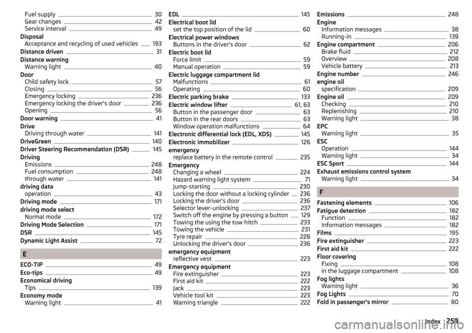
Fuel supply30
Gear changes42
Service interval49
Disposal Acceptance and recycling of used vehicles
193
Distance driven31
Distance warning Warning light
40
Door Child safety lock
57
Closing56
Emergency locking236
Emergency locking the driver's door236
Opening56
Door warning41
Drive Driving through water
141
DriveGreen140
Driver Steering Recommendation (DSR)145
Driving Emissions
248
Fuel consumption248
through water141
driving data operation
43
Driving mode171
driving mode select Normal mode
172
Driving Mode Selection171
DSR145
Dynamic Light Assist72
E
ECO-TIP
49
Eco-tips49
Economical driving Tips
139
Economy mode Warning light
41
EDL145
Electrical boot lid set the top position of the lid
60
Electrical power windows Buttons in the driver's door
62
Electric boot lid Force limit
59
Manual operation59
Electric luggage compartment lid Malfunctions
61
Operating60
Electric parking brake133
Electric window lifter61, 63
Button in the passenger door63
Button in the rear doors63
Window operation malfunctions64
Electronic differential lock (EDL, XDS)145
Electronic immobilizer126
emergency replace battery in the remote control
235
Emergency Changing a wheel
224
Hazard warning light system71
Jump-starting230
Locking the door without a locking cylinder236
Locking the driver's door236
Selector lever-unlocking237
Switch off the engine by pressing a button129
Towing the using the tow hitch233
Towing the vehicle231
Tyre repair228
Unlocking the driver's door236
emergency equipment reflective vest
223
Emergency equipment Fire extinguisher
223
First aid kit222
Jack223
Vehicle tool kit223
Warning triangle222
Emissions248
Engine Information messages
38
Running-in139
Engine compartment206
Brake fluid212
Overview208
Vehicle battery213
Engine number246
engine oil specification
209
Engine oil209
Checking210
Replenishing210
Warning light38
EPC Warning light
35
ESC Operation
144
Warning light34
ESC Sport144
Exhaust emissions control system Warning light
34
F
Fastening elements
106
Fatigue detection182
Function182
Information messages182
Films195
Fire extinguisher223
First aid kit222
Floor covering Fixing
108
in the luggage compartment108
Fog lights Warning light
36
Fog Lights70
Fold in passenger's mirror80
259Index
Page 262 of 276
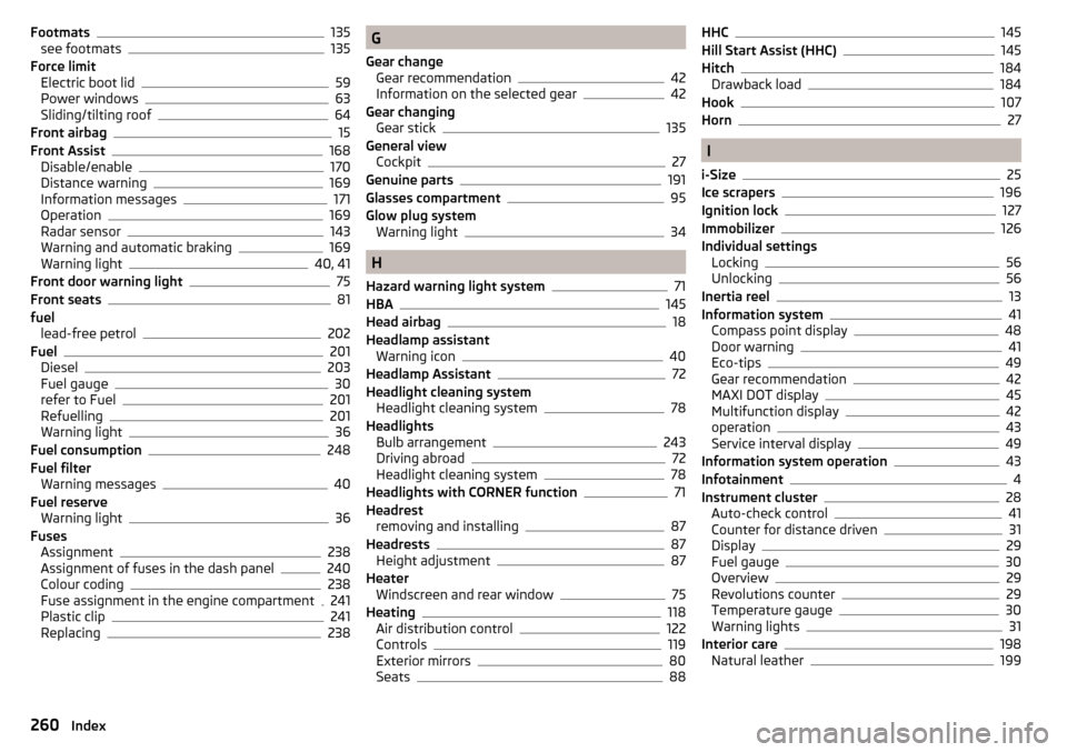
Footmats135
see footmats135
Force limit Electric boot lid
59
Power windows63
Sliding/tilting roof64
Front airbag15
Front Assist168
Disable/enable170
Distance warning169
Information messages171
Operation169
Radar sensor143
Warning and automatic braking169
Warning light40, 41
Front door warning light75
Front seats81
fuel lead-free petrol
202
Fuel201
Diesel203
Fuel gauge30
refer to Fuel201
Refuelling201
Warning light36
Fuel consumption248
Fuel filter Warning messages
40
Fuel reserve Warning light
36
Fuses Assignment
238
Assignment of fuses in the dash panel240
Colour coding238
Fuse assignment in the engine compartment241
Plastic clip241
Replacing238
G
Gear change Gear recommendation
42
Information on the selected gear42
Gear changing Gear stick
135
General view Cockpit
27
Genuine parts191
Glasses compartment95
Glow plug system Warning light
34
H
Hazard warning light system
71
HBA145
Head airbag18
Headlamp assistant Warning icon
40
Headlamp Assistant72
Headlight cleaning system Headlight cleaning system
78
Headlights Bulb arrangement
243
Driving abroad72
Headlight cleaning system78
Headlights with CORNER function71
Headrest removing and installing
87
Headrests87
Height adjustment87
Heater Windscreen and rear window
75
Heating118
Air distribution control122
Controls119
Exterior mirrors80
Seats88
HHC145
Hill Start Assist (HHC)145
Hitch184
Drawback load184
Hook107
Horn27
I
i-Size
25
Ice scrapers196
Ignition lock127
Immobilizer126
Individual settings Locking
56
Unlocking56
Inertia reel13
Information system41
Compass point display48
Door warning41
Eco-tips49
Gear recommendation42
MAXI DOT display45
Multifunction display42
operation43
Service interval display49
Information system operation43
Infotainment4
Instrument cluster28
Auto-check control41
Counter for distance driven31
Display29
Fuel gauge30
Overview29
Revolutions counter29
Temperature gauge30
Warning lights31
Interior care198
Natural leather199
260Index