ignition SKODA SUPERB 2015 3.G / (B8/3V) Owner's Manual
[x] Cancel search | Manufacturer: SKODA, Model Year: 2015, Model line: SUPERB, Model: SKODA SUPERB 2015 3.G / (B8/3V)Pages: 276, PDF Size: 42.14 MB
Page 17 of 276
System descriptionRead and observe
on page 14 first.
The inflation of the airbag is carried out in a fraction of a second.
When the airbags are deployed, they fill with gas and inflate.
A grey white or red, non-harmful gas is released when the airbag is inflated.
This is perfectly normal and is not an indication of a fire in the vehicle.
Depending on the vehicle equipment, the airbag system consists of the
following parts. ▶ Front airbag for the driver and the front passenger » page 15.
▶ Driver’s knee airbag » page 17.
▶ Side airbags » page 17.
▶ Head airbags » page 18.
▶ Airbag warning light in the instrument cluster » page 35.
▶ Key switch for the front passenger airbag » page 19.
▶ Warning light for the front passenger airbag in the middle of the dash panel
» page 19 .
Airbag deployment
Read and observe
on page 14 first.
The airbag system is only functional when the ignition is switched on.
Triggering conditions
It is not possible to generally determine which deployment conditions apply to
the airbag system in every situation. An important role is played by factors
such as the type of object that the vehicle hits (hard/soft), the impact angle, vehicle speed etc.
A decisive factor for the deployment of the airbags is the deceleration which
occurs. If the vehicle deceleration which occurs and is measured during the
collision remains below the prescribed reference values specified in the control
unit, the airbags are not deployed although the vehicle may well suffer severe
damage to the bodywork as a consequence of the accident.
The following airbags will be deployed in the event of a severe frontal
collision.
▶ Driver’s front airbag.
▶ Front passenger airbag.
▶ Driver’s knee airbag.
The following airbags will be deployed in the event of a severe side collision.
▶ Front side airbag on the side of the accident.
▶ Rear side airbag on the side of the accident.
▶ Head airbags on the side of the accident.
When an airbag is deployed, the following events occur. ▶ The interior light comes on (if the automatic operation of the interior light is
switched on - switch
).
▶ The hazard warning lights are switched on.
▶ All doors are unlocked.
▶ The fuel supply to the engine is interrupted.
When there is no air bag deployment?
With minor frontal and side collisions, rear collision, overturning of the vehicle
or vehicle roll-over there is no airbag deployment.
Airbag overview
Introduction
This chapter contains information on the following subjects:
Front airbags
15
Driver’s knee airbag
17
Side airbags
17
Head airbags
18
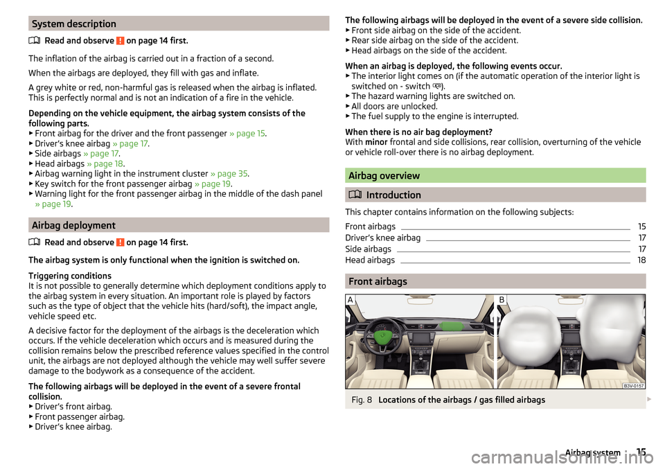
Front airbags
Fig. 8
Locations of the airbags / gas filled airbags
15Airbag system
Page 21 of 276
WARNING (Continued)■When objects are attached to the sun visor, the visor can not be pivoted
to the side windows. This might result in injuries to the occupants if the
head airbag is deployed.■
There must not be any further persons, animals or objects positioned be-
tween the occupants and the deployment area of the airbag. In addition,
none of the occupants should lean their head out of the window when driv-
ing, or extend their arms and hands out of the window.
Note
In vehicles with head airbags, the lettering can be seen on the B-column
cladding.
Deactivating airbags
Introduction
This chapter contains information on the following subjects:
Deactivating airbags
19
Deactivating the front passenger airbag
19
Deactivating airbags
If you sell your vehicle, provide the complete vehicle documentation to the
new owner. Take care to ensure that the information relating to the possibility
of deactivating the front passenger airbag must be included!
If an airbag in the vehicle is to be turned off, then the buyer is to draw atten-
tion to this fact!
Deactivating an airbag should be considered in cases such as the ones below. ▶ If a rear-facing child seat has to be used on the front passenger seat
» page 20 , Transporting children safely .
▶ If it is not possible to maintain a distance of at least 25 cm between the mid-
dle of the steering wheel and chest, despite the driver's seat being correctly
adjusted.
▶ If special attachments are required in the area of the steering wheel because
of a physical disability.
▶ If different seats have been fitted (e.g. orthopaedic seats without side air-
bags).
The front passenger airbag can be switched off with the key-operated switch » Fig. 14 on page 19 - .
We recommend that you ask a ŠKODA service partner to deactivate any other
airbags.
Deactivation indicator
Display of the airbag deactivation » page 35,
Safety systems .
Note
A ŠKODA service partner will be able to inform you which, if any, of your vehi-
cle's airbags can or must be deactivated.
Deactivating the front passenger airbag
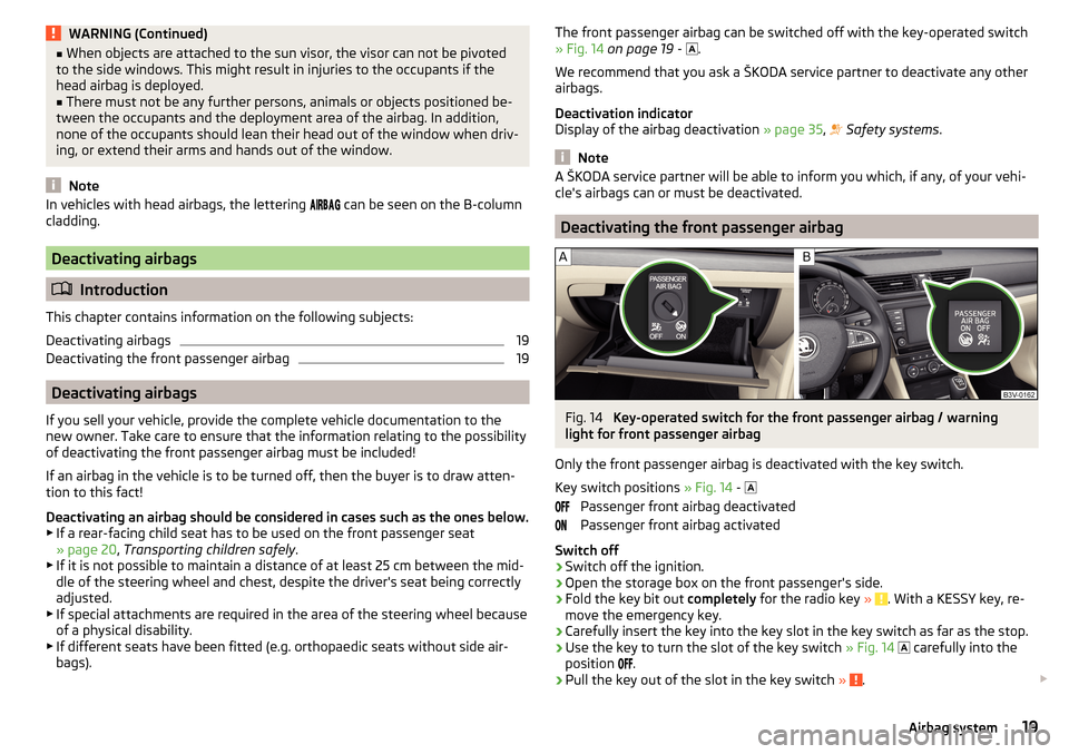
Fig. 14
Key-operated switch for the front passenger airbag / warning
light for front passenger airbag
Only the front passenger airbag is deactivated with the key switch.
Key switch positions » Fig. 14 -
Passenger front airbag deactivated
Passenger front airbag activated
Switch off
›
Switch off the ignition.
›
Open the storage box on the front passenger's side.
›
Fold the key bit out completely for the radio key » . With a KESSY key, re-
move the emergency key.
›
Carefully insert the key into the key slot in the key switch as far as the stop.
›
Use the key to turn the slot of the key switch » Fig. 14
carefully into the
position
.
›
Pull the key out of the slot in the key switch » .
19Airbag system
Page 22 of 276

›Close the storage box on the front passenger's side.›Check that the warning light
under the text » Fig. 14 -
lights up after the ignition is switched on.
Switching on›
Switch off the ignition.
›
Open the storage box on the front passenger's side.
›
Fold the key bit out completely for the radio key » . With a KESSY key, re-
move the emergency key.
›
Carefully insert the key into the key slot in the key switch as far as the stop.
›
Use the key to turn the slot of the key switch » Fig. 14
carefully into the
position
.
›
Pull the key out of the slot in the key switch » .
›
Close the storage box on the front passenger's side.
›
Check that the warning light
under the text
» Fig. 14 -
lights up after the ignition is switched on.
The
warning light goes out 65 seconds after the key switch status has
changed or after the ignition is switched on.
WARNING■ The driver is responsible for whether the airbag is switched on or switch-
ed off.■
Only switch off the airbag when the ignition is switched off! Otherwise a
fault can occur in the system for deactivating the airbag.
■
If the warning lights
flash, the front passenger airbag will not
be deployed in the event of an accident! Have the airbag system checked
by a specialist garage immediately.
■
Do not leave the key inserted in the key-operated switch while driving -
vibrations can cause the key to turn in the slot and switch on the airbag!
The airbag can be triggered unexpectedly in an accident - it may result in
injury or death!
CAUTION
An insufficiently folded out key bit can damage the key switch!Transporting children safely
Child seat
Introduction
This chapter contains information on the following subjects:
Use of a child seat on the front passenger seat
21
Use of the child seat in the front passenger seat
22
Child safety and side airbag
22
Classification of child seats
22
Use of child seats fastened with a seat belt
23
To avoid serious injury or death children are always to be in an appropriate
child safety seat with regards to height, weight, and age.
For safety reasons, we recommend that you always transport child seats on the rear seats.
Child seats complying with the ECE-R 44 Economic Commission for Europe
standard must be used.
Child seats that comply with the ECE-R 44 standard are identified with a test
mark that cannot be removed: a large letter E inside the circle, with the test
number beneath it.
With child safety seats in groups 2 and 3, make sure that the loop-around fit-
tings attached to the child seat headrest is positioned in front of or at the
same height as the loop-around fittings on the B pillar on the passenger side.
WARNING■ One should never carry children, and also not babies! - on one's lap.■Never leave children unattended in the vehicle. Certain outside climatic
conditions can cause life-threatening temperatures in the vehicle.■
The child must be secured in the vehicle during the entire journey! Other-
wise, the child would be thrown through the vehicle in the event of an acci-
dent, causing fatal injuries to both the child and other occupants.
20Safety
Page 29 of 276
Using the system
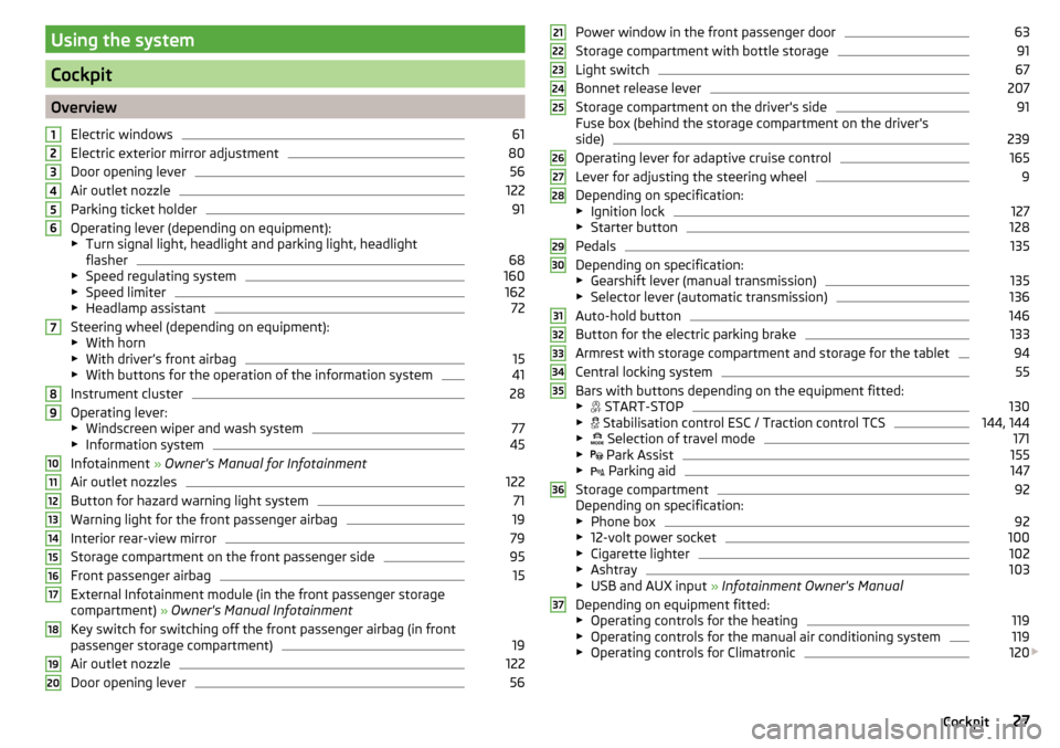
Cockpit
OverviewElectric windows
61
Electric exterior mirror adjustment
80
Door opening lever
56
Air outlet nozzle
122
Parking ticket holder
91
Operating lever (depending on equipment):
▶ Turn signal light, headlight and parking light, headlight
flasher
68
▶ Speed regulating system
160
▶Speed limiter
162
▶Headlamp assistant
72
Steering wheel (depending on equipment):
▶ With horn
▶ With driver’s front airbag
15
▶With buttons for the operation of the information system
41
Instrument cluster
28
Operating lever:
▶ Windscreen wiper and wash system
77
▶Information system
45
Infotainment » Owner's Manual for Infotainment
Air outlet nozzles
122
Button for hazard warning light system
71
Warning light for the front passenger airbag
19
Interior rear-view mirror
79
Storage compartment on the front passenger side
95
Front passenger airbag
15
External Infotainment module (in the front passenger storage
compartment) » Owner's Manual Infotainment
Key switch for switching off the front passenger airbag (in front
passenger storage compartment)
19
Air outlet nozzle
122
Door opening lever
561234567891011121314151617181920Power window in the front passenger door63
Storage compartment with bottle storage
91
Light switch
67
Bonnet release lever
207
Storage compartment on the driver's side
91
Fuse box (behind the storage compartment on the driver's
side)
239
Operating lever for adaptive cruise control
165
Lever for adjusting the steering wheel
9
Depending on specification:
▶ Ignition lock
127
▶Starter button
128
Pedals
135
Depending on specification:
▶ Gearshift lever (manual transmission)
135
▶Selector lever (automatic transmission)
136
Auto-hold button
146
Button for the electric parking brake
133
Armrest with storage compartment and storage for the tablet
94
Central locking system
55
Bars with buttons depending on the equipment fitted:
▶ START-STOP
130
▶
Stabilisation control ESC / Traction control TCS
144, 144
▶
Selection of travel mode
171
▶
Park Assist
155
▶
Parking aid
147
Storage compartment
92
Depending on specification:
▶ Phone box
92
▶12-volt power socket
100
▶Cigarette lighter
102
▶Ashtray
103
▶USB and AUX input » Infotainment Owner's Manual
Depending on equipment fitted: ▶ Operating controls for the heating
119
▶Operating controls for the manual air conditioning system
119
▶Operating controls for Climatronic
120
212223242526272829303132333435363727Cockpit
Page 30 of 276

Storage compartment with bottle storage91
Waste container
93
Note
The arrangement of the controls right-hand drive models may differ from the
layout shown in » Fig. 21. The symbols on the controls and switches are the
same as for left-hand drive models.3839Instruments and warning lights
Instrument cluster
Introduction
This chapter contains information on the following subjects:
Overview
29
Revolutions counter
29
Display
29
Coolant temperature gauge
30
Fuel gauge
30
Counter for distance driven
31
Setting the clock
31
Display in rear centre console
31
The instrument cluster gives the driver basic information such as the current
speed, engine speed, the state of some vehicle systems and the like.
If there is a fault in the instrument cluster, the following message will appear
in the display.
Error: instrument cluster. Workshop!COMBI-INSTRUM_ WORKSHOP
Seek help from a specialist garage.
WARNINGConcentrate fully at all times on your driving! As the driver, you are fully re-
sponsible for road safety.
Note
■ If the message SAFE CP appears in the instrument cluster display, the compo-
nent protection for the instrument cluster is active. Further information
» page 192 , Component protection .■
With the ignition switched on the instruments are also illuminated. The
brightness of the instrument illumination is set automatically depending on
the ambient lighting throughout.
28Using the system
Page 32 of 276
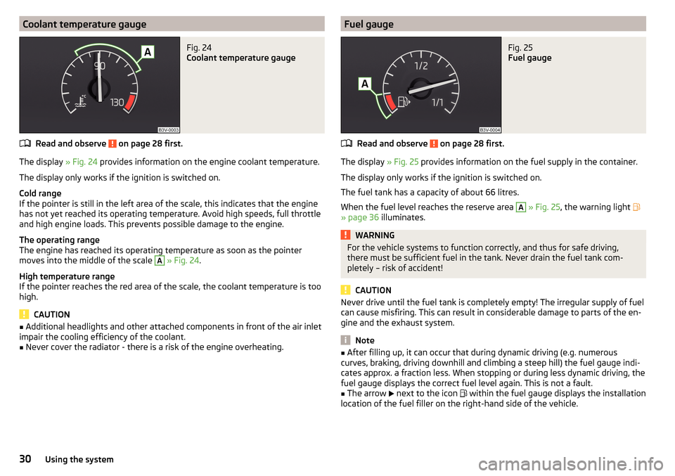
Coolant temperature gaugeFig. 24
Coolant temperature gauge
Read and observe on page 28 first.
The display » Fig. 24 provides information on the engine coolant temperature.
The display only works if the ignition is switched on.
Cold range
If the pointer is still in the left area of the scale, this indicates that the engine has not yet reached its operating temperature. Avoid high speeds, full throttle
and high engine loads. This prevents possible damage to the engine.
The operating range
The engine has reached its operating temperature as soon as the pointer
moves into the middle of the scale
A
» Fig. 24 .
High temperature range
If the pointer reaches the red area of the scale, the coolant temperature is too
high.
CAUTION
■ Additional headlights and other attached components in front of the air inlet
impair the cooling efficiency of the coolant.■
Never cover the radiator - there is a risk of the engine overheating.
Fuel gaugeFig. 25
Fuel gauge
Read and observe on page 28 first.
The display » Fig. 25 provides information on the fuel supply in the container.
The display only works if the ignition is switched on.
The fuel tank has a capacity of about 66 litres.
When the fuel level reaches the reserve area
A
» Fig. 25 , the warning light
» page 36 illuminates.
WARNINGFor the vehicle systems to function correctly, and thus for safe driving,
there must be sufficient fuel in the tank. Never drain the fuel tank com-
pletely – risk of accident!
CAUTION
Never drive until the fuel tank is completely empty! The irregular supply of fuel
can cause misfiring. This can result in considerable damage to parts of the en-
gine and the exhaust system.
Note
■ After filling up, it can occur that during dynamic driving (e.g. numerous
curves, braking, driving downhill and climbing a steep hill) the fuel gauge indi-
cates approx. a fraction less. When stopping or during less dynamic driving, the
fuel gauge displays the correct fuel level again. This is not a fault.■
The arrow
next to the icon
within the fuel gauge displays the installation
location of the fuel filler on the right-hand side of the vehicle.
30Using the system
Page 33 of 276
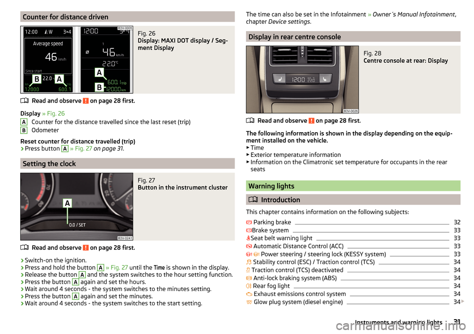
Counter for distance drivenFig. 26
Display: MAXI DOT display / Seg-
ment Display
Read and observe on page 28 first.
Display » Fig. 26
Counter for the distance travelled since the last reset (trip)
Odometer
Reset counter for distance travelled (trip)
›
Press button
A
» Fig. 27 on page 31 .
Setting the clock
Fig. 27
Button in the instrument cluster
Read and observe on page 28 first.
›
Switch-on the ignition.
›
Press and hold the button
A
» Fig. 27 until the
Time
is shown in the display.
›
Release the button
A
and the system switches to the hour setting function.
›
Press the button
A
again and set the hours.
›
Wait around 4 seconds - the system switches to the minutes setting.
›
Press the button
A
again and set the minutes.
›
Wait around 4 seconds - the system switches to the start setting.
ABThe time can also be set in the Infotainment » Owner´s Manual Infotainment ,
chapter Device settings .
Display in rear centre console
Fig. 28
Centre console at rear: Display
Read and observe on page 28 first.
The following information is shown in the display depending on the equip-
ment installed on the vehicle. ▶ Time
▶ Exterior temperature information
▶ Information on the Climatronic set temperature for occupants in the rear
seats
Warning lights
Introduction
This chapter contains information on the following subjects:
Parking brake
32
Brake system
33
Seat belt warning light
33
Automatic Distance Control (ACC)
33
Power steering / steering lock (KESSY system)
33
Stability control (ESC) / Traction control (TCS)
34
Traction control (TCS) deactivated
34
Anti-lock braking system (ABS)
34
Rear fog light
34
Exhaust emissions control system
34
Glow plug system (diesel engine)
34
31Instruments and warning lights
Page 34 of 276
Engine electronics check (petrol engine)35 Safety systems35
Tyre pressure
35
Brake linings
36
Fuel reserve
36
Lane departure warning (Lane Assist)
36
Turn signal system
36
Trailer turn signal lights
36
Fog lights
36
Speed regulating system / Speed limiter
37
Brake pedal (automatic transmission)
37
Parking brake - Auto Hold function
37
Main beam
37
Automatic transmission
37
Rear seat belt warning light
37
Alternator
37
Coolant
38
Engine oil pressure too low
38
Engine oil level
38
AdBlue ®
39
Lamp failure
39
Diesel particulate filter (diesel engine)
39
Windscreen washer fluid level
40
Headlamp assistant
40
START-STOP system
40
Low temperature displayed
40
Water in the fuel filter (diesel engine)
40
Automatic Distance Control (ACC)
40
Distance warning (Front Assist)
40
Advance warning / emergency braking (Front Assist)
41
Economy mode
41
Adaptive chassis control (DCC) fault
41
Service
41
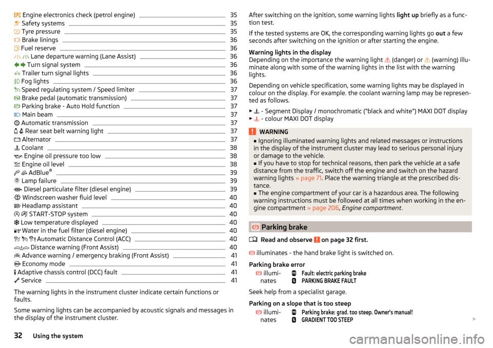
The warning lights in the instrument cluster indicate certain functions or
faults.
Some warning lights can be accompanied by acoustic signals and messages in
the display of the instrument cluster.
After switching on the ignition, some warning lights light up briefly as a func-
tion test.
If the tested systems are OK, the corresponding warning lights go out a few
seconds after switching on the ignition or after starting the engine.
Warning lights in the display
Depending on the importance the warning light
(danger) or
(warning) illu-
minate along with some of the warning lights in the list with the warning
lights.
Depending on vehicle specification, some warning lights may be displayed in
colour on the display. For example. the coolant warning lamp may be represen-
ted as follows.
▶ - Segment Display / monochromatic (“black and white”) MAXI DOT display
▶ - colour MAXI DOT displayWARNING■
Ignoring illuminated warning lights and related messages or instructions
in the display of the instrument cluster may lead to serious personal injury
or damage to the vehicle.■
If you have to stop for technical reasons, then park the vehicle at a safe
distance from the traffic, switch off the engine and switch on the hazard
warning lights » page 71. Place the warning triangle at the prescribed dis-
tance.
■
The engine compartment of your car is a hazardous area. The following
warning instructions must be followed at all times when working in the en-
gine compartment » page 206, Engine compartment .
Parking brake
Read and observe
on page 32 first.
illuminates - the hand brake light is switched on.
Parking brake error
illumi-
nates
Fault: electric parking brakePARKING BRAKE FAULT
Seek help from a specialist garage.
Parking on a slope that is too steep
illumi-
nates
Parking brake: grad. too steep. Owner's manual!GRADIENT TOO STEEP
32Using the system
Page 35 of 276
Find a parking space on a flat surface or on a slope that is not so steep.
Brake systemRead and observe
on page 32 first.
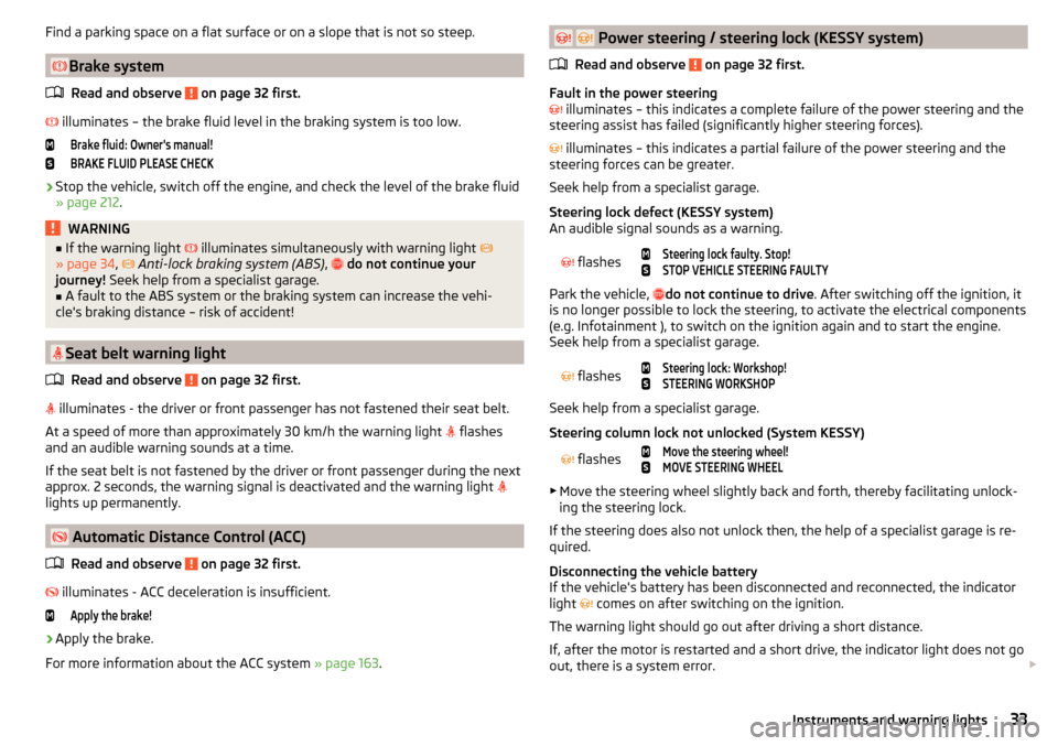
illuminates – the brake fluid level in the braking system is too low.
Brake fluid: Owner's manual!BRAKE FLUID PLEASE CHECK›
Stop the vehicle, switch off the engine, and check the level of the brake fluid
» page 212 .
WARNING■
If the warning light illuminates simultaneously with warning light
» page 34 , Anti-lock braking system (ABS) , do not continue your
journey! Seek help from a specialist garage.■
A fault to the ABS system or the braking system can increase the vehi-
cle's braking distance – risk of accident!
Seat belt warning light
Read and observe
on page 32 first.
illuminates - the driver or front passenger has not fastened their seat belt.
At a speed of more than approximately 30 km/h the warning light flashes
and an audible warning sounds at a time.
If the seat belt is not fastened by the driver or front passenger during the next
approx. 2 seconds, the warning signal is deactivated and the warning light
lights up permanently.
Automatic Distance Control (ACC)
Read and observe
on page 32 first.
illuminates - ACC deceleration is insufficient.
Apply the brake!›
Apply the brake.
For more information about the ACC system » page 163.
Power steering / steering lock (KESSY system)
Read and observe
on page 32 first.
Fault in the power steering
illuminates – this indicates a complete failure of the power steering and the
steering assist has failed (significantly higher steering forces).
illuminates – this indicates a partial failure of the power steering and the
steering forces can be greater.
Seek help from a specialist garage.
Steering lock defect (KESSY system)
An audible signal sounds as a warning.
flashes
Steering lock faulty. Stop!STOP VEHICLE STEERING FAULTY
Park the vehicle, do not continue to drive
. After switching off the ignition, it
is no longer possible to lock the steering, to activate the electrical components
(e.g. Infotainment ), to switch on the ignition again and to start the engine.
Seek help from a specialist garage.
flashes
Steering lock: Workshop!STEERING WORKSHOP
Seek help from a specialist garage.
Steering column lock not unlocked (System KESSY)
flashes
Move the steering wheel!MOVE STEERING WHEEL
▶ Move the steering wheel slightly back and forth, thereby facilitating unlock-
ing the steering lock.
If the steering does also not unlock then, the help of a specialist garage is re-
quired.
Disconnecting the vehicle battery
If the vehicle's battery has been disconnected and reconnected, the indicator
light comes on after switching on the ignition.
The warning light should go out after driving a short distance.
If, after the motor is restarted and a short drive, the indicator light does not go
out, there is a system error.
33Instruments and warning lights
Page 36 of 276
Seek help from a specialist garage.
Stability control (ESC) / Traction control (TCS)Read and observe
on page 32 first.
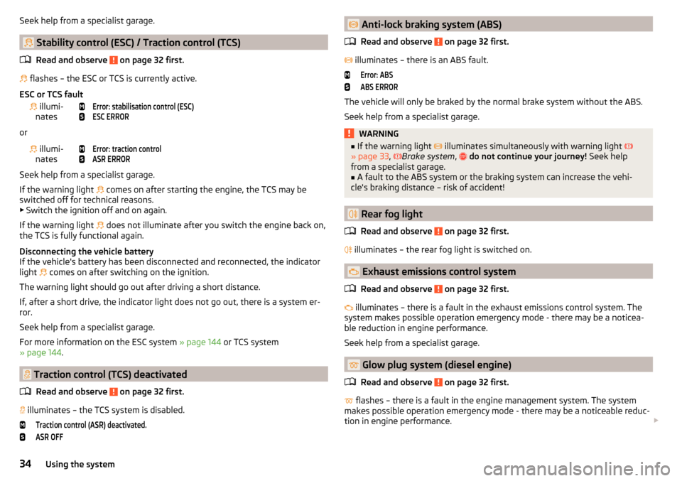
flashes – the ESC or TCS is currently active.
ESC or TCS fault
illumi-
nates
Error: stabilisation control (ESC)ESC ERROR
or
illumi-
nates
Error: traction controlASR ERROR
Seek help from a specialist garage.
If the warning light comes on after starting the engine, the TCS may be
switched off for technical reasons. ▶ Switch the ignition off and on again.
If the warning light does not illuminate after you switch the engine back on,
the TCS is fully functional again.
Disconnecting the vehicle battery
If the vehicle's battery has been disconnected and reconnected, the indicator
light comes on after switching on the ignition.
The warning light should go out after driving a short distance.
If, after a short drive, the indicator light does not go out, there is a system er-
ror.
Seek help from a specialist garage.
For more information on the ESC system » page 144 or TCS system
» page 144 .
Traction control (TCS) deactivated
Read and observe
on page 32 first.
illuminates – the TCS system is disabled.
Traction control (ASR) deactivated.ASR OFF Anti-lock braking system (ABS)
Read and observe
on page 32 first.
illuminates – there is an ABS fault.
Error: ABSABS ERROR
The vehicle will only be braked by the normal brake system without the ABS.
Seek help from a specialist garage.
WARNING■ If the warning light illuminates simultaneously with warning light
» page 33 , Brake system , do not continue your journey! Seek help
from a specialist garage.■
A fault to the ABS system or the braking system can increase the vehi-
cle's braking distance – risk of accident!
Rear fog light
Read and observe
on page 32 first.
illuminates – the rear fog light is switched on.
Exhaust emissions control system
Read and observe
on page 32 first.
illuminates – there is a fault in the exhaust emissions control system. The
system makes possible operation emergency mode - there may be a noticea-
ble reduction in engine performance.
Seek help from a specialist garage.
Glow plug system (diesel engine)
Read and observe
on page 32 first.
flashes – there is a fault in the engine management system. The system
makes possible operation emergency mode - there may be a noticeable reduc-
tion in engine performance.
34Using the system