fuses SKODA SUPERB 2015 3.G / (B8/3V) Owner's Manual
[x] Cancel search | Manufacturer: SKODA, Model Year: 2015, Model line: SUPERB, Model: SKODA SUPERB 2015 3.G / (B8/3V)Pages: 276, PDF Size: 42.14 MB
Page 5 of 276
Traffic jam assistant179Assistant for emergencies179
Traffic sign recognition
180
Fatigue detection
182
Tyre pressure monitoring
183
Hitch and trailer
184
Hitch
184
Trailer
185
General Maintenance
Care and maintenance
190
Service work, adjustments and technical
alterations
190
Washing vehicle
193
Cleaning vehicle exterior
194
Interior care
198
Inspecting and replenishing
201
Fuel
201
AdBlue ®
and its refilling
204
Engine compartment
206
Engine oil
209
Coolant
210
Brake fluid
212
Vehicle battery
213
Wheels
217
Tyres and wheel rims
217
Winter operation
220
Do-it-yourself
Emergency equipment and self-help
222
Emergency equipment
222
Changing a wheel
224
Puncture repair kit
228
Jump-starting
230
Towing the vehicle
231
Remote control and removable light
233Emergency unlocking/locking235Replacing windscreen wiper blades237
Fuses and light bulbs
238
Fuses
238
Bulbs
242
Technical data
Technical data
246
Basic vehicle data
246
Vehicle-specific information depending on
engine type
252
Index
3Table of Contents
Page 240 of 276
›Turn on the ignition and press the lever into position 4
» page 78 , Wind-
screen wipers and washers .
Move the windscreen wiper arms into the home position.
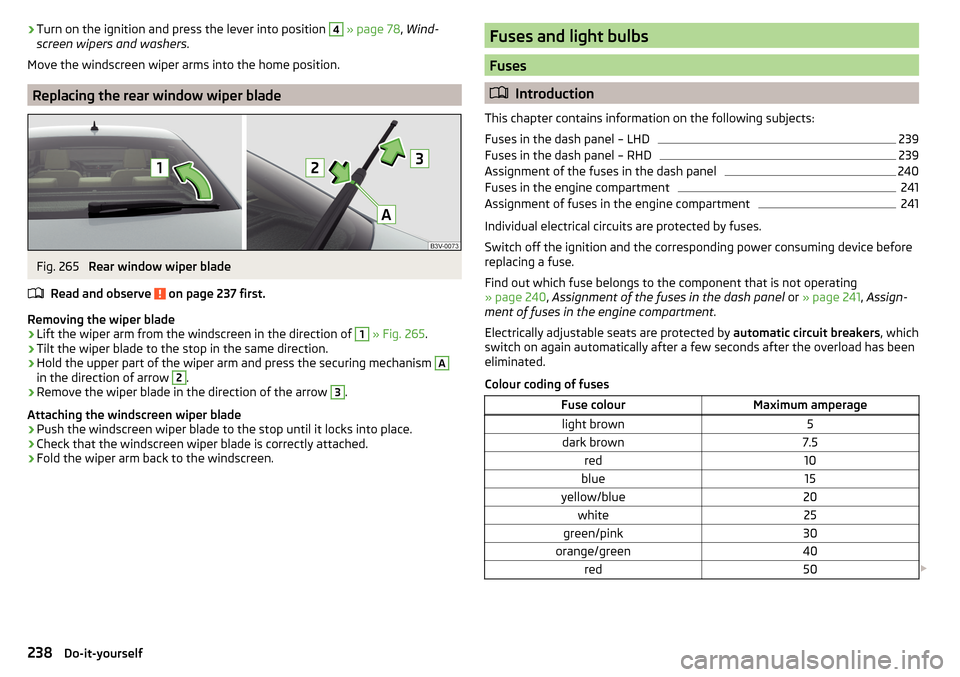
Replacing the rear window wiper blade
Fig. 265
Rear window wiper blade
Read and observe
on page 237 first.
Removing the wiper blade
›
Lift the wiper arm from the windscreen in the direction of
1
» Fig. 265 .
›
Tilt the wiper blade to the stop in the same direction.
›
Hold the upper part of the wiper arm and press the securing mechanism
A
in the direction of arrow
2
.
›
Remove the wiper blade in the direction of the arrow
3
.
Attaching the windscreen wiper blade
›
Push the windscreen wiper blade to the stop until it locks into place.
›
Check that the windscreen wiper blade is correctly attached.
›
Fold the wiper arm back to the windscreen.
Fuses and light bulbs
Fuses
Introduction
This chapter contains information on the following subjects:
Fuses in the dash panel – LHD
239
Fuses in the dash panel – RHD
239
Assignment of the fuses in the dash panel
240
Fuses in the engine compartment
241
Assignment of fuses in the engine compartment
241
Individual electrical circuits are protected by fuses.
Switch off the ignition and the corresponding power consuming device before
replacing a fuse.
Find out which fuse belongs to the component that is not operating
» page 240 , Assignment of the fuses in the dash panel or » page 241 , Assign-
ment of fuses in the engine compartment .
Electrically adjustable seats are protected by automatic circuit breakers, which
switch on again automatically after a few seconds after the overload has been
eliminated.
Colour coding of fuses
Fuse colourMaximum amperagelight brown5dark brown7.5red10blue15yellow/blue20white25green/pink30orange/green40red50 238Do-it-yourself
Page 241 of 276
WARNINGAlways read and observe the warnings before completing any work in the
engine compartment » page 206.
CAUTION
■
“Never repair” fuses, and do not replace them with fuses of a higher amper-
age – risk of fire! This may also cause damage at another part of the electrical
system.■
If a newly inserted fuse blows again after a short time, have the electrical
system checked as quickly as possible by a specialist garage.
■
A blown fuses is recognisable by the molten metal strip. Replace the faulty
fuse with a new one of the same amperage.
Note
■
We recommend always carrying replacement fuses in the vehicle. A box of
replacement fuses and bulbs can be purchased from ŠKODA Genuine Accesso-
ries.■
There can be several power consuming devices for one fuse.
■
Multiple fuses may exist for a single power consuming device.
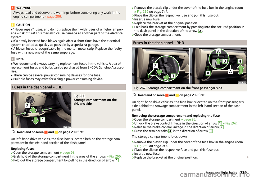
Fuses in the dash panel – LHD
Fig. 266
Storage compartment on the
driver's side
Read and observe and on page 239 first.
On left-hand drive vehicles, the fuse box is located behind the storage com- partment in the left-hand section of the dash panel.
Replacing fuses
›
Open the storage compartment » page 91.
›
Grab hold of the storage compartment in the area of the arrows » Fig. 266.
›
Fold out the storage compartment by pulling in the direction of arrow
1
.
›Remove the plastic clip under the cover of the fuse box in the engine room
» Fig. 269 on page 241 .›
Place the clip on the respective fuse and pull this fuse out.
›
Insert a new fuse.
›
Replace the bracket at the original position.
›
Fold back the storage compartment by pressing into the secured position in
the dash panel in the direction of the arrow
2
.
›
Close the storage compartment.
Fuses in the dash panel – RHD
Fig. 267
Storage compartment on the front passenger side
Read and observe
and on page 239 first.
On right-hand drive vehicles, the fuse box is located on the front passenger's side behind the stowage compartment in the left-hand section of the dash
panel.
Removing the storage compartment and replacing the fuse
›
Open the storage compartment » page 95.
›
Unlock the brake control linkage in the direction of arrow
1
» Fig. 267 .
›
Release the brake control linkage in the direction of arrow
2
.
›
Press the retainer tabs
A
in the direction of arrow
3
.
The storage compartment folds down.
›
Remove the plastic clip under the cover of the fuse box in the engine room
» Fig. 269 on page 241 .
›
Place the clip on the respective fuse and pull this fuse out.
›
Insert a new fuse.
›
Replace the bracket at the original position.
239Fuses and light bulbs
Page 242 of 276
Installing the storage compartment›Raise the storage compartment in the direction of the arrow 4.›
Overcome the resistance of the detents
A
.
›
Insert the brake control linkage in the opposite direction to arrow
2
.
›
Lock the brake control linkage in the opposite direction to arrow
1
.
›
Close the storage compartment.
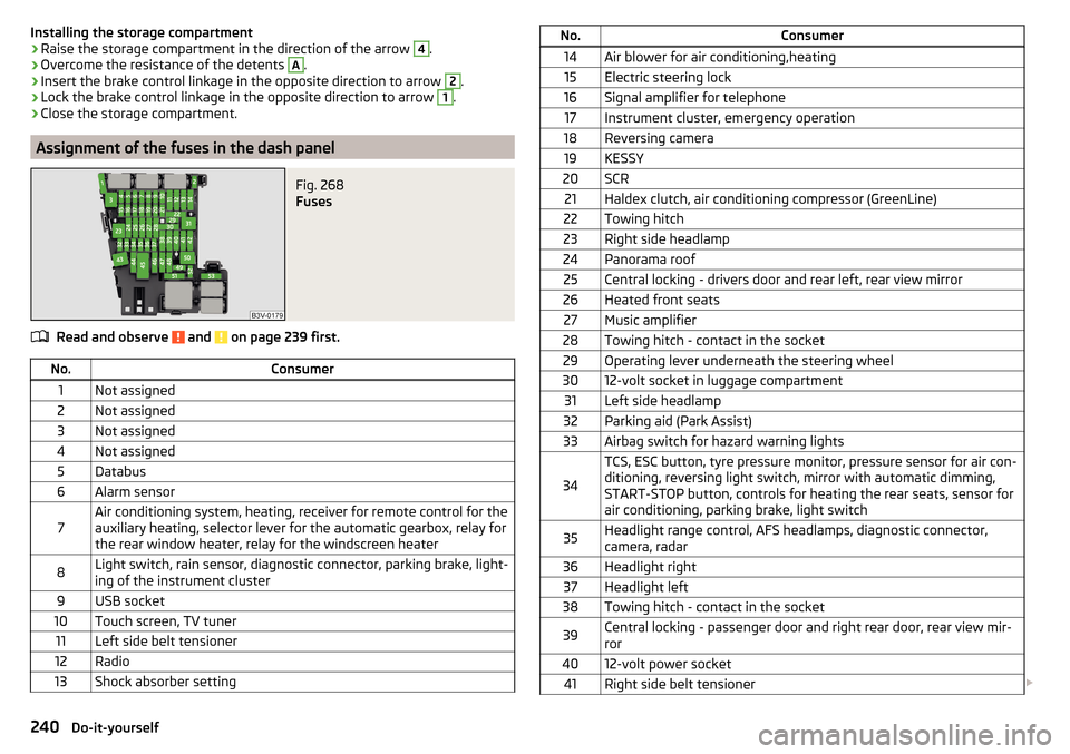
Assignment of the fuses in the dash panel
Fig. 268
Fuses
Read and observe and on page 239 first.
No.Consumer1Not assigned2Not assigned3Not assigned4Not assigned5Databus6Alarm sensor7Air conditioning system, heating, receiver for remote control for the
auxiliary heating, selector lever for the automatic gearbox, relay for
the rear window heater, relay for the windscreen heater8Light switch, rain sensor, diagnostic connector, parking brake, light-
ing of the instrument cluster9USB socket10Touch screen, TV tuner11Left side belt tensioner12Radio13Shock absorber settingNo.Consumer14Air blower for air conditioning,heating15Electric steering lock16Signal amplifier for telephone17Instrument cluster, emergency operation18Reversing camera19KESSY20SCR21Haldex clutch, air conditioning compressor (GreenLine)22Towing hitch23Right side headlamp24Panorama roof25Central locking - drivers door and rear left, rear view mirror26Heated front seats27Music amplifier28Towing hitch - contact in the socket29Operating lever underneath the steering wheel3012-volt socket in luggage compartment31Left side headlamp32Parking aid (Park Assist)33Airbag switch for hazard warning lights
34
TCS, ESC button, tyre pressure monitor, pressure sensor for air con-
ditioning, reversing light switch, mirror with automatic dimming,
START-STOP button, controls for heating the rear seats, sensor for
air conditioning, parking brake, light switch35Headlight range control, AFS headlamps, diagnostic connector,
camera, radar36Headlight right37Headlight left38Towing hitch - contact in the socket39Central locking - passenger door and right rear door, rear view mir-
ror4012-volt power socket41Right side belt tensioner 240Do-it-yourself
Page 243 of 276
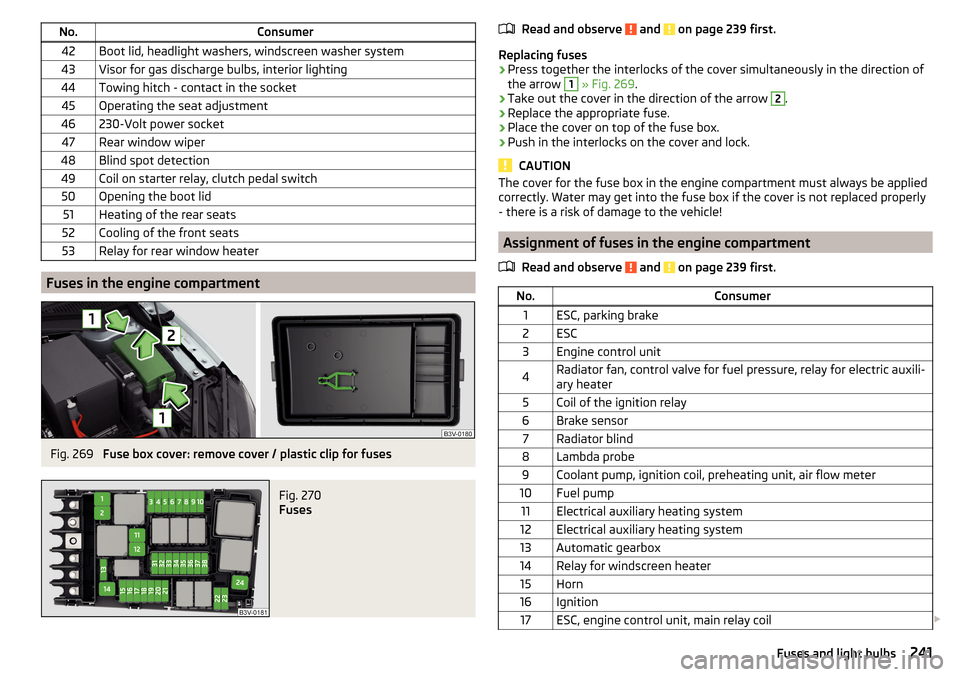
No.Consumer42Boot lid, headlight washers, windscreen washer system43Visor for gas discharge bulbs, interior lighting44Towing hitch - contact in the socket45Operating the seat adjustment46230-Volt power socket47Rear window wiper48Blind spot detection49Coil on starter relay, clutch pedal switch50Opening the boot lid51Heating of the rear seats52Cooling of the front seats53Relay for rear window heater
Fuses in the engine compartment
Fig. 269
Fuse box cover: remove cover / plastic clip for fuses
Fig. 270
Fuses
Read and observe and on page 239 first.
Replacing fuses
›
Press together the interlocks of the cover simultaneously in the direction of
the arrow
1
» Fig. 269 .
›
Take out the cover in the direction of the arrow
2
.
›
Replace the appropriate fuse.
›
Place the cover on top of the fuse box.
›
Push in the interlocks on the cover and lock.
CAUTION
The cover for the fuse box in the engine compartment must always be applied
correctly. Water may get into the fuse box if the cover is not replaced properly
- there is a risk of damage to the vehicle!
Assignment of fuses in the engine compartment
Read and observe
and on page 239 first.
No.Consumer1ESC, parking brake2ESC3Engine control unit4Radiator fan, control valve for fuel pressure, relay for electric auxili-
ary heater5Coil of the ignition relay6Brake sensor7Radiator blind8Lambda probe9Coolant pump, ignition coil, preheating unit, air flow meter10Fuel pump11Electrical auxiliary heating system12Electrical auxiliary heating system13Automatic gearbox14Relay for windscreen heater15Horn16Ignition17ESC, engine control unit, main relay coil 241Fuses and light bulbs
Page 245 of 276
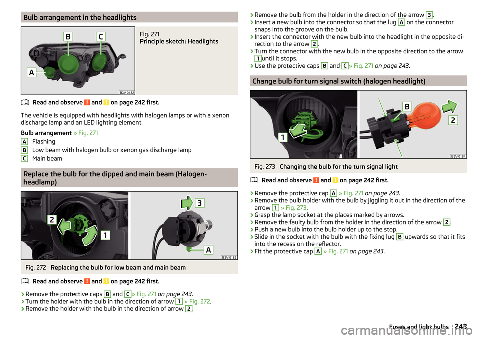
Bulb arrangement in the headlightsFig. 271
Principle sketch: Headlights
Read and observe and on page 242 first.
The vehicle is equipped with headlights with halogen lamps or with a xenon
discharge lamp and an LED lighting element.
Bulb arrangement » Fig. 271
Flashing
Low beam with halogen bulb or xenon gas discharge lamp
Main beam
Replace the bulb for the dipped and main beam (Halogen- headlamp)
Fig. 272
Replacing the bulb for low beam and main beam
Read and observe
and on page 242 first.
›
Remove the protective caps
B
and
C
» Fig. 271 on page 243 .
›
Turn the holder with the bulb in the direction of arrow
1
» Fig. 272 .
›
Remove the holder with the bulb in the direction of arrow
2
.
ABC›Remove the bulb from the holder in the direction of the arrow 3.›Insert a new bulb into the connector so that the lug A on the connector
snaps into the groove on the bulb.›
Insert the connector with the new bulb into the headlight in the opposite di-
rection to the arrow
2
.
›
Turn the connector with the new bulb in the opposite direction to the arrow
1
until it stops.
›
Use the protective caps
B
and
C
» Fig. 271 on page 243 .
Change bulb for turn signal switch (halogen headlight)
Fig. 273
Changing the bulb for the turn signal light
Read and observe
and on page 242 first.
›
Remove the protective cap
A
» Fig. 271 on page 243 .
›
Remove the bulb holder with the bulb by jiggling it out in the direction of the
arrow
1
» Fig. 273 .
›
Grasp the lamp socket at the places marked by arrows.
›
Remove the faulty bulb from the holder in the direction of the arrow
2
.
›
Push a new bulb into the bulb holder up to the stop.
›
Slide in the socket with the bulb with the fixing lug
B
upwards so that it fits
into the recess on the reflector.
›
Fit the protective cap
A
» Fig. 271 on page 243 .
243Fuses and light bulbs
Page 247 of 276
›Carefully remove the connector from the lamp assembly in the direction of
the arrow 4.
Fitting›
Slide the plug in the opposite direction of the arrow
4
» Fig. 275 into the
light.
The locks on the plug must be inserted securely.
›
Insert the lamp with the holes
D
onto the studs
C
in the body.
›
Carefully press the light into the studs on the bodywork.
Ensure that the wiring harness does not become pinched between the body
and the lamp.
›
Screw the tail lamp into place and install the cover.
The cover must engage securely.
If you are not sure whether the wiring harness has become pinched, we rec-
ommend that you have the light connection checked by a specialist garage.
CAUTION
■ Ensure that the wiring harness does not become pinched between the body
and the lamp when it is being refitted – risk of damage to the electrical instal-
lation and risk of water ingress.■
Ensure that the vehicle paintwork and the tail lamp are not damaged when
removing and installing the lamp.
■
Make sure that when refitting the seal
C
» Fig. 276 on page 245 it is inser-
ted correctly. Water and dirt may get into the lamp if the cover is not replaced
properly - there is a risk of damage to the lamp!
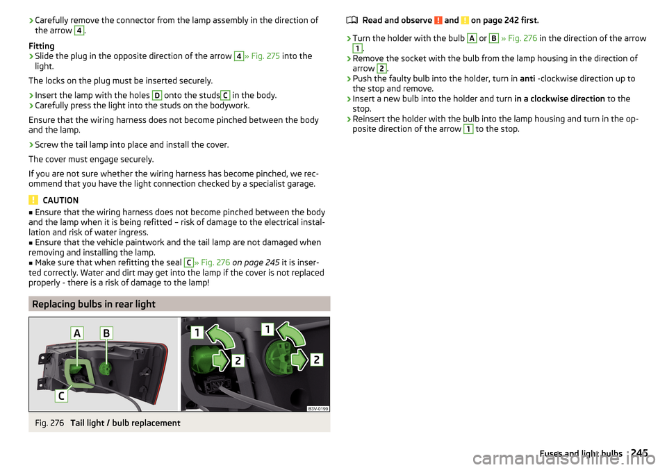
Replacing bulbs in rear light
Fig. 276
Tail light / bulb replacement
Read and observe and on page 242 first.›
Turn the holder with the bulb
A
or
B
» Fig. 276 in the direction of the arrow
1
.
›
Remove the socket with the bulb from the lamp housing in the direction of
arrow
2
.
›
Push the faulty bulb into the holder, turn in anti -clockwise direction up to
the stop and remove.
›
Insert a new bulb into the holder and turn in a clockwise direction to the
stop.
›
Reinsert the holder with the bulb into the lamp housing and turn in the op-
posite direction of the arrow
1
to the stop.
245Fuses and light bulbs
Page 262 of 276
Footmats135
see footmats135
Force limit Electric boot lid
59
Power windows63
Sliding/tilting roof64
Front airbag15
Front Assist168
Disable/enable170
Distance warning169
Information messages171
Operation169
Radar sensor143
Warning and automatic braking169
Warning light40, 41
Front door warning light75
Front seats81
fuel lead-free petrol
202
Fuel201
Diesel203
Fuel gauge30
refer to Fuel201
Refuelling201
Warning light36
Fuel consumption248
Fuel filter Warning messages
40
Fuel reserve Warning light
36
Fuses Assignment
238
Assignment of fuses in the dash panel240
Colour coding238
Fuse assignment in the engine compartment241
Plastic clip241
Replacing238
G
Gear change Gear recommendation
42
Information on the selected gear42
Gear changing Gear stick
135
General view Cockpit
27
Genuine parts191
Glasses compartment95
Glow plug system Warning light
34
H
Hazard warning light system
71
HBA145
Head airbag18
Headlamp assistant Warning icon
40
Headlamp Assistant72
Headlight cleaning system Headlight cleaning system
78
Headlights Bulb arrangement
243
Driving abroad72
Headlight cleaning system78
Headlights with CORNER function71
Headrest removing and installing
87
Headrests87
Height adjustment87
Heater Windscreen and rear window
75
Heating118
Air distribution control122
Controls119
Exterior mirrors80
Seats88
HHC145
Hill Start Assist (HHC)145
Hitch184
Drawback load184
Hook107
Horn27
I
i-Size
25
Ice scrapers196
Ignition lock127
Immobilizer126
Individual settings Locking
56
Unlocking56
Inertia reel13
Information system41
Compass point display48
Door warning41
Eco-tips49
Gear recommendation42
MAXI DOT display45
Multifunction display42
operation43
Service interval display49
Information system operation43
Infotainment4
Instrument cluster28
Auto-check control41
Counter for distance driven31
Display29
Fuel gauge30
Overview29
Revolutions counter29
Temperature gauge30
Warning lights31
Interior care198
Natural leather199
260Index
Page 265 of 276
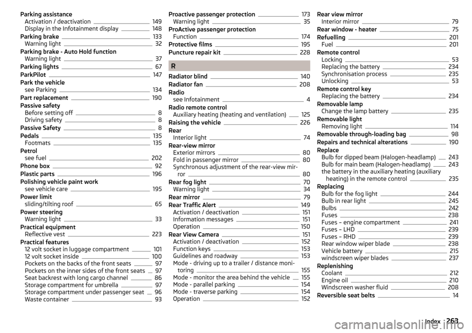
Parking assistanceActivation / deactivation149
Display in the Infotainment display148
Parking brake133
Warning light32
Parking brake - Auto Hold function Warning light
37
Parking lights67
ParkPilot147
Park the vehicle see Parking
134
Part replacement190
Passive safety Before setting off
8
Driving safety8
Passive Safety8
Pedals135
Footmats135
Petrol see fuel
202
Phone box92
Plastic parts196
Polishing vehicle paint work see vehicle care
195
Power limit sliding/tilting roof
65
Power steering Warning light
33
Practical equipment Reflective vest
223
Practical features 12 volt socket in luggage compartment
101
12 volt socket inside100
Pockets on the backs of the front seats97
Pockets on the inner sides of the front seats97
Seat backrest with long cargo channel86
Storage compartment for umbrella97
Storage compartment under passenger seat96
Waste container93
Proactive passenger protection173
Warning light35
ProActive passenger protection Function
174
Protective films195
Puncture repair kit228
R
Radiator blind
140
Radiator fan208
Radio see Infotainment
4
Radio remote control Auxiliary heating (heating and ventilation)
125
Raising the vehicle226
Rear Interior light
74
Rear-view mirror Exterior mirrors
80
Fold in passenger mirror80
Synchronous adjustment of the rear-view mir- ror
80
Rear fog light70
Warning light34
Rear mirror79
Rear Traffic Alert149
Activation / deactivation151
Information messages151
Operation150
Rear View Camera151
Activation / deactivation152
Function keys153
Guidelines and roadway153
Mode - driving up to a trailer / distance moni- toring
155
Mode - monitor the area behind the vehicle155
Mode - parallel parking154
Mode - traverse parking154
Operation152
Rear view mirror Interior mirror79
Rear window - heater75
Refuelling201
Fuel201
Remote control Locking
53
Replacing the battery234
Synchronisation process235
Unlocking53
Remote control key Replacing the battery
234
Removable lamp Change the lamp battery
235
Removable light Removing light
114
Removable through-loading bag98
Repairs and technical alterations190
Replace Bulb for dipped beam (Halogen-headlamp)
243
Bulb for main beam (Halogen-headlamp)243
the battery in the auxiliary heating (auxiliary heating) in the remote control
235
Replacing Bulb for the fog light
244
Bulb in rear light245
Bulbs242
Fuses238
Fuses – engine compartment241
Fuses – LHD239
Fuses – RHD239
Rear window wiper blade238
Vehicle battery215
windscreen wiper blades237
Replenishing Coolant
212
Engine oil210
Windscreen washer fluid208
Reversible seat belts14
263Index