wheel bolts SKODA SUPERB 2015 3.G / (B8/3V) Owner's Manual
[x] Cancel search | Manufacturer: SKODA, Model Year: 2015, Model line: SUPERB, Model: SKODA SUPERB 2015 3.G / (B8/3V)Pages: 276, PDF Size: 42.14 MB
Page 219 of 276
Wheels
Tyres and wheel rims
Introduction
This chapter contains information on the following subjects:
Notes on using wheels
217
Tyre pressure
217
Tyre wear
218
Tyre wear indicator and wheel replacement
219
Tyre damage
219
Unidirectional tyres
219
Spare wheel
219
Tyre label
220
Only use tyres or wheel rims that have been approved by ŠKODA for your mod-
el of vehicle.
WARNINGFor reasons of driving safety, do not replace tyres individually.
Note
■ We recommend that any work on the wheels or tyres be carried out by a spe-
cialist garage.■
We recommend that you use wheel rims, tyres, full wheel trims and snow
chains from ŠKODA Original Accessories.
Notes on using wheels
Read and observe
on page 217 first.
New tyres do not offer optimum grip during the first 500 km and appropriate
care should therefore be taken when driving.
Always fit the tyres with the deeper tread depth to the front wheels.
Tyre storage
Identify disassembled tyres so that the previous direction of rotation can be
maintained if the tyres are reassembled.
Always store wheels or tyres in a cool, dry place that is as dark as possible.
Tyres which are not fixed to a wheel trim should be stored upright.
Tyre age
Tyres age and lose their original characteristics, even if they are not being
used. The service life of the tyres is 6 years. Therefore, we recommend not us-
ing tyres that are older than 6 years.
Wheel bolts
Wheels and wheel bolts are matched to each other in terms of design. We rec-
ommend that you use wheel rims, tyres and wheel bolts from ŠKODA Original
Accessories.WARNINGNever use tyres if you do not know anything about the condition and age.
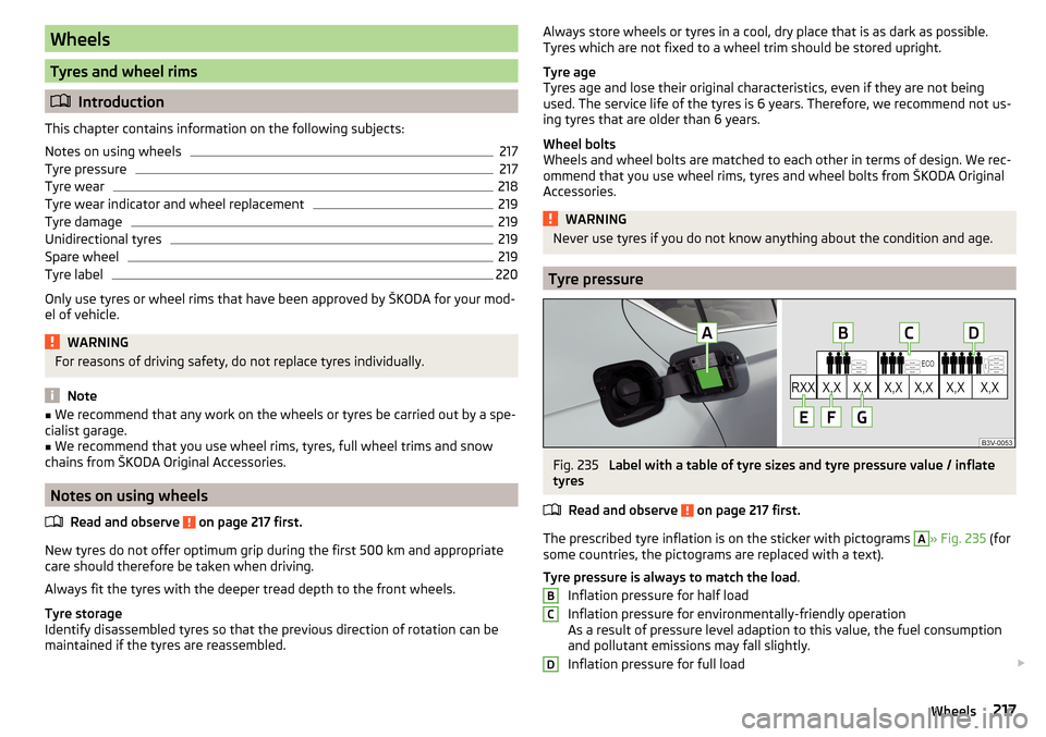
Tyre pressure
Fig. 235
Label with a table of tyre sizes and tyre pressure value / inflate
tyres
Read and observe
on page 217 first.
The prescribed tyre inflation is on the sticker with pictograms
A
» Fig. 235 (for
some countries, the pictograms are replaced with a text).
Tyre pressure is always to match the load .
Inflation pressure for half load
Inflation pressure for environmentally-friendly operation
As a result of pressure level adaption to this value, the fuel consumption
and pollutant emissions may fall slightly.
Inflation pressure for full load
BCD217Wheels
Page 225 of 276

reflective vestFig. 239
Front door: Storage compart-
ment for the reflective vest
The reflective vest can be stowed in the storage compartment
A
inside the
storage compartment of the front door » Fig. 239.
It is possible to store the reflective vests for the passengers on the rear seat in
the storage compartment in the rear doors.
Fire extinguisher
Fig. 240
Fire extinguisher
The fire extinguisher is attached by two straps in a bracket under the front
passenger's seat.
Removing/attaching
›
Loosen the two straps by pulling the buckles in the direction of the arrow
» Fig. 240 .
›
Remove the fire extinguisher.
›
Secure the fire extinguisher by placing it back into the holder and fastening
with straps.
Please read the instructions which are attached to the fire extinguisher.
Pay attention to the expiration date of the fire extinguisher. If the fire extin-
guisher is used after the expiration date, its proper function is not assured.
WARNINGThe fire extinguisher must always be secured safely so that they do not
come loose when making an emergency braking or in a vehicle collision
which could cause injuries to occupants.
Note
The fire extinguisher is part of the scope of delivery in certain countries only.
Vehicle tool kit
Fig. 241
Vehicle tool kit
The tool kit is housed in a box in the spare wheel compartment or in this stor-
age space.
Depending on the vehicle configuration, it may not contain all the compo-
nents listed in the on-board tool kit.
Screwdriver
Adapter for anti-theft wheel bolts
Towing eye
Clamps for removing the wheel trims
Jack with sign
Crank for the jack
Wheel wrench
Extraction pliers for wheel bolt caps
Breakdown kit
123456789223Emergency equipment and self-help
Page 226 of 276

WARNINGThe factory-supplied lifting jack is only intended for your model of vehicle.
Under no circumstances attempt to lift heavier vehicles or other loads.
CAUTION
■ Screw the jack back into the starting position before storing in the box with
the tool kit.■
Ensure that the vehicle tool kit is safely secured in the boot.
■
Ensure that the box is always secured with the strap.
Note
The declaration of conformity is included with the jack or the log folder.
Changing a wheel
Introduction
This chapter contains information on the following subjects:
Preparation
224
Removing/stowing the wheel
224
Full wheel trim
225
Wheel bolts
225
Anti-theft wheel bolts
225
Loosening/tightening wheel bolts
226
Raising the vehicle
226
Remove the wheel / fix
227
Follow-up tasks
227
For your own safety and the safety of the passengers, the following instruc-
tions must be observed before changing a wheel on the road.
Switch on the hazard warning lights system.
Place the warning triangle at the prescribed distance.
Park the vehicle as far away as possible from the flowing traffic.
Choose a location with a flat, solid surface.
Have all the occupants get out. The passengers should not stand on the
road (instead they should remain behind a crash barrier, for instance) while
the wheel is being changed.
Tyres with increased puncture resistance
Some vehicles may be fitted with tyres at the factory that have increased
puncture resistance (so-called “SEAL” tyres).
These vehicles are delivered without a puncture repair kit, spare wheel and
appropriate hand tools.
If the tyres with increased puncture resistance are replaced with tyres that
have no increased puncture resistance then the vehicle should be equipped
with a puncture repair kit, spare wheel and appropriate hand tools.
Preparation
Before changing the wheel, the following work must be carried out.
›
Switch off the engine.
›
For vehicles with manual transmission engage 1st gear.
›
On vehicles with
automatic transmission place the selector lever in the P po-
sition.
›
The parking brake switch.
›
Uncouple any trailers.
Removing/stowing the wheel
Fig. 242
Take out wheel
The wheel is located in a well under the floor covering in the boot and is fixed
in place with a special screw.
Take out wheel
›
Open the tailgate.
›
Lift up the floor in the luggage compartment.
›
Loosen the retaining belt and take out the box with the tool kit.
›
Unscrew the special screws in the direction of arrow » Fig. 242.
›
Remove the wheel.
224Do-it-yourself
Page 227 of 276

Store wheel away›Place the wheel into the wheel well with the wheel rim pointing downward.›
Pull the fixing band through the opposite holes in the wheel rim.
›
Screw on the special screw in the opposite direction to the arrow » Fig. 242
until the wheel is safely secured.
›
Replace the box with the tool kit into the wheel and secure it with the tape.
›
Fold back the floor in the luggage compartment.
›
Shut the boot lid.
Full wheel trim
Before removing the wheel bolts, remove the wheel cover.
Extracting
›
Hook the clamp found in the vehicle tool kit » page 223 into the reinforced
edge of the wheel trim.
›
Push the wheel wrench through the clamp, support on the tyre and pull off
the wheel trim.
Fitting
›
Press the wheel trim onto the wheel rim at the designated valve opening.
›
Then press the trim into the wheel rim until its entire circumference locks
correctly in place.
Notes from the factory or from the ŠKODA Original accessory delivered trim.
▶ When using an anti-theft wheel bolt, make sure that this has been fitted ac-
cording to the position marked on the back of the wheel cover position.
▶ On the back of the wheel cover, the position for the anti-theft wheel bolt is
marked by means of a symbol. If the wheel cover is set outside the position
marked for the anti-theft wheel bolt, there is a risk of damaging the wheel
cover.
If wheel trims are fitted, an adequate flow of air must be assured in order to
cool the brake system.
CAUTION
Use the pressure of your hand only, do not strike the full wheel trim. The cover
could be damaged.
Note
We recommend that you use hub caps from ŠKODA Original Accessories.Wheel boltsFig. 243
Remove the cap
Before removing the wheel bolts, remove the covering caps.
Extracting
›
Push the extraction pliers » page 223 sufficiently far onto the cap until the
inner catches of the pliers are positioned at the collar of the cap.
›
Remove the cap in the direction of the arrow » Fig. 243.
Fitting
›
Push the caps onto the wheel bolts up to the stop.
Anti-theft wheel bolts
Fig. 244
Principle sketch: Anti-theft
wheel bolt with adapter
The anti-theft wheel bolts protect the wheels from theft. These can only be
loosened or tightened with the use of adapter
B
» Fig. 244 .
›
Remove the full wheel trim or the caps of the wheel bolts.
›
Insert adapter
B
» Fig. 244 with the toothed side all the way into the inner
teeth in the head of the anti-theft wheel bolts
A
.
›
Push the wheel wrench onto the adapter
B
up to the stop.
›
Loosen or tighten the wheel bolt » page 226.
›
Remove the adapter.
225Emergency equipment and self-help
Page 228 of 276
›Replace the wheel trim or the caps.
To be equipped for a possible wheel change, the adapter for the anti-theft
wheel bolts must always be kept in the vehicle. The adapter is stowed in the
tool kit.
The position of the anti-theft wheel bolt is marked on the back of the wheel
cover with every ŠKODA supplied original equipment hub cap or directly at the
factors.
When using an anti-theft wheel bolt, make sure that this has been fitted ac-
cording to the position marked on the back of the wheel cover position.
Note
■ Note the code number which is embossed both on the adapter and also on
the end of each anti-theft wheel bolt. This number can be used to purchase a
replacement adapter from ŠKODA Original Parts if necessary.■
The anti-theft wheel bolt set and adapter can be purchased from a ŠKODA
Partner.
Loosening/tightening wheel bolts
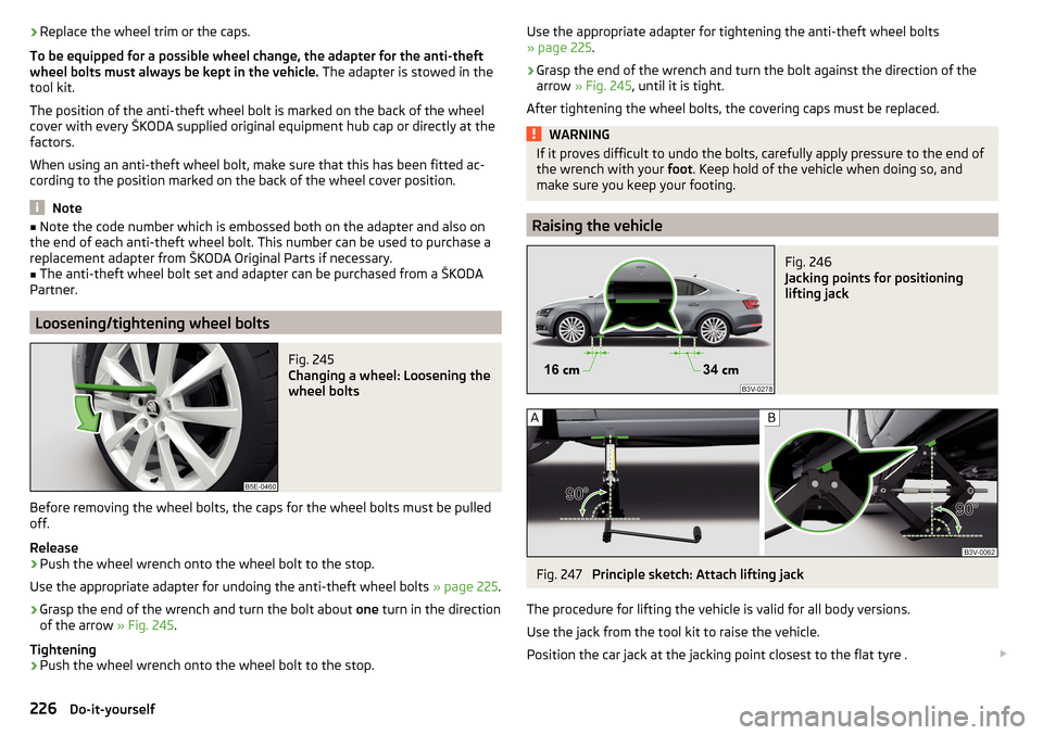
Fig. 245
Changing a wheel: Loosening the
wheel bolts
Before removing the wheel bolts, the caps for the wheel bolts must be pulled
off.
Release
›
Push the wheel wrench onto the wheel bolt to the stop.
Use the appropriate adapter for undoing the anti-theft wheel bolts » page 225.
›
Grasp the end of the wrench and turn the bolt about one turn in the direction
of the arrow » Fig. 245.
Tightening
›
Push the wheel wrench onto the wheel bolt to the stop.
Use the appropriate adapter for tightening the anti-theft wheel bolts
» page 225 .›
Grasp the end of the wrench and turn the bolt against the direction of the
arrow » Fig. 245 , until it is tight.
After tightening the wheel bolts, the covering caps must be replaced.
WARNINGIf it proves difficult to undo the bolts, carefully apply pressure to the end of
the wrench with your foot. Keep hold of the vehicle when doing so, and
make sure you keep your footing.
Raising the vehicle
Fig. 246
Jacking points for positioning
lifting jack
Fig. 247
Principle sketch: Attach lifting jack
The procedure for lifting the vehicle is valid for all body versions.
Use the jack from the tool kit to raise the vehicle.
Position the car jack at the jacking point closest to the flat tyre .
226Do-it-yourself
Page 229 of 276
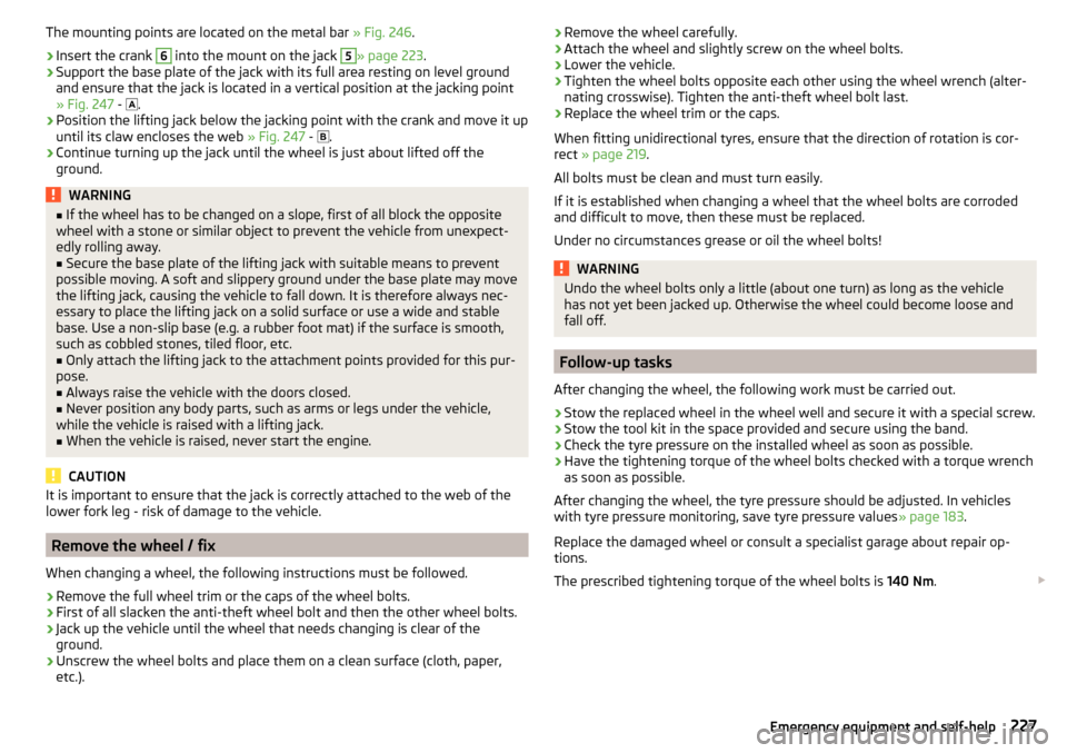
The mounting points are located on the metal bar » Fig. 246.›
Insert the crank
6
into the mount on the jack
5
» page 223 .
›
Support the base plate of the jack with its full area resting on level ground
and ensure that the jack is located in a vertical position at the jacking point
» Fig. 247 -
.
›
Position the lifting jack below the jacking point with the crank and move it up
until its claw encloses the web » Fig. 247 -
.
›
Continue turning up the jack until the wheel is just about lifted off the
ground.
WARNING■ If the wheel has to be changed on a slope, first of all block the opposite
wheel with a stone or similar object to prevent the vehicle from unexpect-
edly rolling away.■
Secure the base plate of the lifting jack with suitable means to prevent
possible moving. A soft and slippery ground under the base plate may move
the lifting jack, causing the vehicle to fall down. It is therefore always nec-
essary to place the lifting jack on a solid surface or use a wide and stable
base. Use a non-slip base (e.g. a rubber foot mat) if the surface is smooth,
such as cobbled stones, tiled floor, etc.
■
Only attach the lifting jack to the attachment points provided for this pur-
pose.
■
Always raise the vehicle with the doors closed.
■
Never position any body parts, such as arms or legs under the vehicle,
while the vehicle is raised with a lifting jack.
■
When the vehicle is raised, never start the engine.
CAUTION
It is important to ensure that the jack is correctly attached to the web of the
lower fork leg - risk of damage to the vehicle.
Remove the wheel / fix
When changing a wheel, the following instructions must be followed.
›
Remove the full wheel trim or the caps of the wheel bolts.
›
First of all slacken the anti-theft wheel bolt and then the other wheel bolts.
›
Jack up the vehicle until the wheel that needs changing is clear of the
ground.
›
Unscrew the wheel bolts and place them on a clean surface (cloth, paper,
etc.).
› Remove the wheel carefully.›Attach the wheel and slightly screw on the wheel bolts.›
Lower the vehicle.
›
Tighten the wheel bolts opposite each other using the wheel wrench (alter-
nating crosswise). Tighten the anti-theft wheel bolt last.
›
Replace the wheel trim or the caps.
When fitting unidirectional tyres, ensure that the direction of rotation is cor-
rect » page 219 .
All bolts must be clean and must turn easily.
If it is established when changing a wheel that the wheel bolts are corroded and difficult to move, then these must be replaced.
Under no circumstances grease or oil the wheel bolts!
WARNINGUndo the wheel bolts only a little (about one turn) as long as the vehicle
has not yet been jacked up. Otherwise the wheel could become loose and
fall off.
Follow-up tasks
After changing the wheel, the following work must be carried out.
›
Stow the replaced wheel in the wheel well and secure it with a special screw.
›
Stow the tool kit in the space provided and secure using the band.
›
Check the tyre pressure on the installed wheel as soon as possible.
›
Have the tightening torque of the wheel bolts checked with a torque wrench
as soon as possible.
After changing the wheel, the tyre pressure should be adjusted. In vehicles
with tyre pressure monitoring, save tyre pressure values » page 183.
Replace the damaged wheel or consult a specialist garage about repair op-
tions.
The prescribed tightening torque of the wheel bolts is 140 Nm.
227Emergency equipment and self-help
Page 230 of 276

WARNING■If the wheel bolts are tightened to a too low tightening torque, the rim
can come loose when the car is moving. A tightening torque which is too
high can damage the bolts and threads and this can result in permanent
deformation of the contact surfaces on the rim.■
Drive cautiously and only at a moderate speed until the tightening torque
has been checked.
Puncture repair kit
Introduction
This chapter contains information on the following subjects:
Components of the puncture repair kits
228
General information
229
Preparations for using the breakdown kit
229
Sealing and inflating the tyre
229
Notes for driving with repaired tyres
230
Use the breakdown kit to reliably repair tyre damage caused by foreign bodies
or a puncture with diameters up to approx. 4 mm.
Performing a repair with the breakdown kit not at all intended to replace a
permanent repair on the tyre. Its purpose is to get you to the nearest specialist
garage.
The wheel must not be removed during repair.
Do not remove foreign bodies , which have penetrated the wheel profile from
the tyre (e.g. screws or nails).
Immediately replace the tyre that was repaired using the breakdown kit, or
consult a specialist garage about repair options.
WARNING■ The sealant is hazardous to heath. Remove immediately if it comes into
contact with the skin.■
Observe the manufacturer's usage instructions for the breakdown kit.
Note
A new bottle of sealant can be purchased from ŠKODA Original Parts.Components of the puncture repair kitsFig. 248
Principle sketch: Components of the breakdown kit
Read and observe
on page 228 first.
Kit components » Fig. 248
Sticker with speed designation “max. 80 km/h”/“max. 50 mph” Valve remover
Inflation hose with plug
Air compressor
Button for releasing the tyre pressure
12 volt cable connector
Tyre inflation hose
Tyre inflation pressure indicator
ON and OFF switch
Tyre inflation bottle with sealing agent
Replacement valve core
The valve remover
2
has a slot at its lower end which fits into the valve core.
The kit is located in a box under the floor covering in the luggage compart-
ment. The kit contains a sealant and an air compressor.
Note
The declaration of conformity is included with the air compressor or the log
folder.1234567891011228Do-it-yourself
Page 258 of 276
Index
A
abroad lead-free petrol
202
Abroad Headlights
72
ABS Operation
144
Warning light34
ACC163
Acceptance and recycling of used vehicles193
Accessories190
Adaptive chassis control Warning light
41
Adaptive Chassis Control171
Adaptive cruise control automatic stop-start
165
Information messages168
Operation164
Operation Overview165
Set/change the desired speed166
special driving conditions167
Start control166
Stop/resume control166
Adaptive Cruise Control163
Radar sensor143
Set the clearance level167
Adaptive headlight see xenon headlight
69
AdBlue204, 205
refilling204
replenish205
Warning light39
Adjust Auxiliary heating (auxiliary heating and ventila- tion)
124
AdjustingExterior mirrors80
Steering wheel9
Adjusting the seats8
Adjustment Front seats
81
Headlight beam67
Headrests87
Seats82
Advance warning / emergency braking Warning light
41
AHL see xenon headlight
69
Air-conditioning system Air outlet vents
122
Airbag14
Deactivating19
Deactivating the front passenger airbag19
Deployment15
Front airbag15
Head airbag18
Knee airbag17
Modifications and damage to the airbag system 192
Side airbag
17
Warning light35
Airbag system14
Air conditioning118
Air distribution control122
Climatronic120
Manual air conditioning119
Air distribution control122
Air outlet vents122
Alarm Enable/disable
57
Switch off57
Trailer189
Triggering57
Alcantara cleaning
199
Anodized partsRefer to vehicle maintenance196
Anti-lock braking system (ABS)144
Anti-theft alarm system Enable/disable
57
Trailer189
Anti-theft wheel bolts225
Armrest Front
85
rear98
Rear86
artificial leather199
Ashtray103
removal104
Assistant for blind spot monitoring177
Activation / deactivation178
Driving conditions and warnings178
Information messages179
Operation177
Assistant for emergencies179
Operating conditions180
Operation180
Assist systems142
Auto-check control41
Auto Hold146
Warning light37
Auto Hold function146
Warning light37
Automatic Distance Control Warning light
33
Warning lights40
Automatic driving lamp control69
Automatic gearbox Selector lever-emergency unlocking
237
Selector lever lock137
Starting-off and driving138
Tiptronic137
Using the selector lever136
Automatic gearbox modes136
Automatic load deactivation216
256Index
Page 269 of 276

Materials199
Natural leather199
Plastic parts196
Polishing vehicle paint work195
Rubber seals196
Safety belt200
Seat covers200
Under-body protections198
washing193
Vehicle condition see Auto-check control
41
Vehicle data sticker246
Vehicle data sticker and nameplate Vehicle data sticker and nameplate
246
Vehicle dimensions249, 250
Vehicle height249, 250
Vehicle Identification Number (VIN)246
Vehicle length249, 250
Vehicle tool kit223
Vehicle width249, 250
Ventilation Front seats
89
Seats88
vest holder for reflective vest
223
VIN Vehicle Identification Number
246
Virtual pedal61
Visibility75
Visors see front sun visors
76
see Sun screen76
W
Warning lights
31
Warning symbols see Warning lights
31
Warning triangle222
warning when speeding44
Washing Automatic car wash system194
by hand193
High-pressure cleaner194
Washing vehicles193
Waste container93
Water in the fuel filter Warning light
40
Warning messages40
Weather conditions190
Wheel bolts Anti-theft wheel bolts
225
Caps225
Loosening and tightening226
Wheel rims217
Wheels Age of wheels
217
Changing224
Driving style218
Full trim225
General information217
Load index220
Snow chains221
Speed symbol220
Storage of wheels217
Tyre damage219
Tyre pressure217
Tyre size220
Tyre wear218
Tyre wear indicator219
unidirectional tyres219
Wheel balance218
Wheel replacement219
Winter tyres221
Wi-Fi Connection
50
Password50
Password change51
Setting51
Wi-Fi Direct Connection51
Password change51
Setting51
Window operation61
Button in the passenger door63
Button in the rear doors63
Buttons in the driver's door62
Comfort operation63
Malfunctions64
Window wiper Replacing the rear window wiper blade
238
Windscreen Heater
75
Windscreen washer fluid Checking
208
Replenishing208
Warning light40
Winter208
Windscreen washers Windscreen washers
78
Windscreen washer system208
Windscreen wipers automatic rear window wipers
78
operation78
Replacing the windscreen wipers237
Windscreen washer fluid208
Windscreen wipers and washers77
Winter operation220
De-icing windows196
Snow chains221
Winter tyres221
Winter tyres See Wheels
221
Wiper blades198
Service position of the windscreen wiper arms 237
Wiper interval
78
Wipers Maintaining wiper blades
198
267Index