ignition SKODA SUPERB 2016 3.G / (B8/3V) User Guide
[x] Cancel search | Manufacturer: SKODA, Model Year: 2016, Model line: SUPERB, Model: SKODA SUPERB 2016 3.G / (B8/3V)Pages: 336, PDF Size: 53.89 MB
Page 41 of 336
Auto Hold functionRead and observe
on page 34 first.
illuminates - the Auto Hold function is activated.
For more information about the Auto-Hold Function » page 204.
Main beam
Read and observe
on page 34 first.
lights up – the main beam or the headlight flasher is switched on.
Automatic gearbox
Read and observe
on page 34 first.
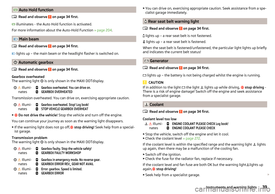
Gearbox overheated
The warning light is only shown in the MAXI DOTdisplay.
Illumi-
nates
Gearbox overheated. You can drive on.GEARBOX OVERHEATED
Transmission overheated. You can drive on, exercising appropriate caution.
Illumi-
nates
Gearbox overheated. Stop! Log book!STOP VEHICLE GEARBOX OVERHEAT
▶
Do not drive the vehicle! Stop the vehicle and turn off the engine.
You can continue your journey as soon as the warning light disappears.
▶ If the warning light does not go off,
stop driving! Seek help from a special-
ist garage.
Transmission problem
The warning light is only shown in the MAXI DOTdisplay.
Illumi-
nates
Gearbox faulty. Stop the vehicle safely!GEARBOX FAULTY WORKSHOP Illumi-
nates
Gearbox in emergency mode. No reverse gear.GEARBOX ERROR REV_ GEAR NOT AVAIL Illumi-
nates
Error: gearbox. Speed is limited.GEARBOX ERROR▶ You can drive on, exercising appropriate caution. Seek assistance from a spe-
cialist garage immediately.
Rear seat belt warning light
Read and observe
on page 34 first.
lights up – a rear seat belt is not fastened.
lights up – a rear seat belt is fastened.
When the seat belt is fastened/unfastened, the particular light lights up briefly
and indicates the current belt status!
Generator
Read and observe
on page 34 first.
lights up – the battery is not being charged whilst the engine is running.
CAUTION
If in addition to the light
the light lights up while driving, stop driving -
There is a risk of engine damage! Switch off the engine and seek assistance
from a specialist garage.
Coolant
Read and observe
on page 34 first.
Coolant level too low
Illumi-
nates
ENGINE COOLANT PLEASE CHECK Log book!ENGINE COOLANT PLEASE CHECK
▶ Stop the vehicle, switch off the engine and let it cool.
▶ Check the coolant level » page 272.
If the coolant level is within the specified range and the warning light lights
up again, then there may be a malfunction of the cooling fan.
▶ Switch off the ignition.
▶ Check the fuse for the radiator fan, replace if necessary.
If the coolant level and fan fuse are both OK but the warning light lights up
again,
stop driving!
▶ Seek help from a specialist garage.
39Instruments and warning lights
Page 46 of 336
Setting the clockFig. 23
Button in the instrument cluster
›
Switch on the ignition.
›
Press and hold the button
A
» Fig. 23 until the
time
is shown in the display.
›
Release the button
A
and the system switches to the hour setting function.
›
Press the button
A
again and set the hours.
›
Wait around 4 seconds - the system switches to the minutes setting.
›
Press the button
A
again and set the minutes.
›
Wait around 4 seconds - the system switches to the initial setting.
The time can also be set in the Infotainment menu by tapping
→
→
timeand date
.
Gear recommendation
Fig. 24
Information on the selected
gear / Gear recommendation
A suitable engaged gear or, where appropriate, a recommended gear is dis-
played, with the aim of conserving the life of the engine and increasing driving
efficiency.
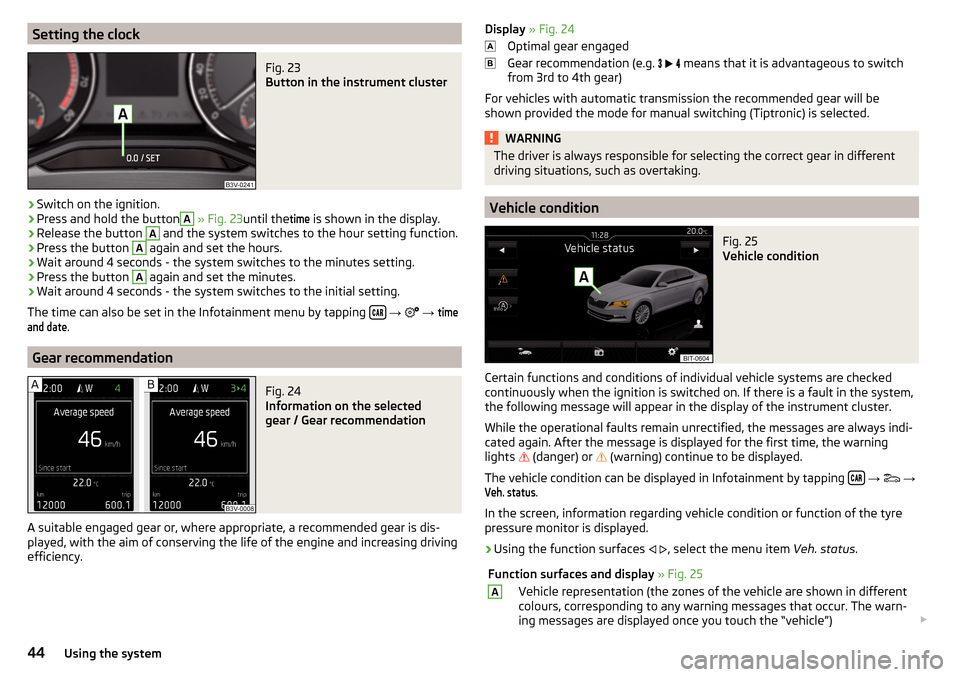
Display » Fig. 24
Optimal gear engaged
Gear recommendation (e.g.
means that it is advantageous to switch
from 3rd to 4th gear)
For vehicles with automatic transmission the recommended gear will be
shown provided the mode for manual switching (Tiptronic) is selected.WARNINGThe driver is always responsible for selecting the correct gear in different
driving situations, such as overtaking.
Vehicle condition
Fig. 25
Vehicle condition
Certain functions and conditions of individual vehicle systems are checked
continuously when the ignition is switched on. If there is a fault in the system,
the following message will appear in the display of the instrument cluster.
While the operational faults remain unrectified, the messages are always indi-
cated again. After the message is displayed for the first time, the warning
lights
(danger) or
(warning) continue to be displayed.
The vehicle condition can be displayed in Infotainment by tapping
→
→
Veh. status
.
In the screen, information regarding vehicle condition or function of the tyre
pressure monitor is displayed.
›
Using the function surfaces
, select the menu item Veh. status.
Function surfaces and display » Fig. 25AVehicle representation (the zones of the vehicle are shown in different
colours, corresponding to any warning messages that occur. The warn-
ing messages are displayed once you touch the “vehicle”) 44Using the system
Page 48 of 336
Driving data (Multifunction display)
Introduction
This chapter contains information on the following subjects:
Information overview
46
Display Infotainment
46
Warning when exceeding the set speed
47
Memory
47
The driving data display is only possible with the ignition switched on. After
the ignition is switched on, the function that was last selected before switch-
ing off the ignition is displayed.
If vehicles with MAXI DOTdisplay do not show the driving data after switching
on the ignition, select the menu item
Driving data
in the main menu and confirm
» page 48 .
The units and the display of some information can be set in Infotainment by
tapping
→
→
units
.
Note
The setting of the information display is stored in the active user account per-
sonalisation » page 49.
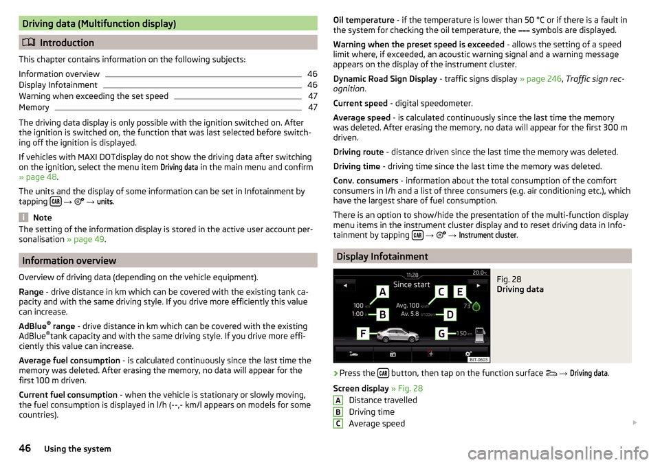
Information overview
Overview of driving data (depending on the vehicle equipment).
Range - drive distance in km which can be covered with the existing tank ca-
pacity and with the same driving style. If you drive more efficiently this value
can increase.
AdBlue ®
range - drive distance in km which can be covered with the existing
AdBlue ®
tank capacity and with the same driving style. If you drive more effi-
ciently this value can increase.
Average fuel consumption - is calculated continuously since the last time the
memory was deleted. After erasing the memory, no data will appear for the
first 100 m driven.
Current fuel consumption - when the vehicle is stationary or slowly moving,
the fuel consumption is displayed in l/h (--,- km/l appears on models for some
countries).
Oil temperature - if the temperature is lower than 50 °C or if there is a fault in
the system for checking the oil temperature, the symbols are displayed.
Warning when the preset speed is exceeded - allows the setting of a speed
limit where, if exceeded, an acoustic warning signal and a warning message
appears on the display of the instrument cluster.
Dynamic Road Sign Display - traffic signs display » page 246, Traffic sign rec-
ognition .
Current speed - digital speedometer.
Average speed - is calculated continuously since the last time the memory
was deleted. After erasing the memory, no data will appear for the first 300 m
driven.
Driving route - distance driven since the last time the memory was deleted.
Driving time - driving time since the last time the memory was deleted.
Conv. consumers - information about the total consumption of the comfort
consumers in l/h and a list of three consumers (e.g. air conditioning etc.), which
have the largest share of fuel consumption.
There is an option to show/hide the presentation of the multi-function display
menu items in the instrument cluster display and to reset driving data in Info-
tainment by tapping
→
→
Instrument cluster
.
Display Infotainment
Fig. 28
Driving data
›
Press the button, then tap on the function surface
→
Driving data
.
Screen display » Fig. 28
Distance travelled
Driving time
Average speed
ABC46Using the system
Page 49 of 336
Average fuel consumption
Transit point rating (DriveGreen
Function)
Range (if the estimated range is less than 300 km, the vehicle starts to ap-
proach the symbol
)
Approximate range
Use the function surfaces
to select one of the following presets.
▶ Since start - Driving data for the individual trip
▶ Long-term - Long-term driving data
▶ Since refuel - Data since refuelling
Warning when exceeding the set speed
The system offers the possibility to set a speed limit beyond which an acoustic
warning signal will sound and the following warning message appears in the
display of the instrument cluster.
Adjust the speed limit while the vehicle is stationary
›
Select the menu item
Warning at
at ( ) or
(
) and confirm.
›
Set the desired speed limit is 5 km/h steps.
›
Confirm the set value, or wait several seconds; your settings will be saved
automatically.
Adjusting the speed limit while the vehicle is moving
›
Select the menu item
Warning at
at ( ) or
(
) and confirm.
›
Drive at the desired speed.
›
Confirm the current speed as the speed limit.
The set speed limit can be manually adjusted later if needed.
Reset the speed limit
›
Select the menu item
Warning at
at ( ) or
(
) and confirm.
›
By confirming the stored value, the speed limit is reset.
The speed limit set mode is stored even after the ignition is switched off and
on. After a gap between driving exceeding 2 hours, the pre-set speed limit is
deactivated.
DEFGMemoryFig. 29
Memory display: MAXI DOT dis-
play (
) / Segment display (
)
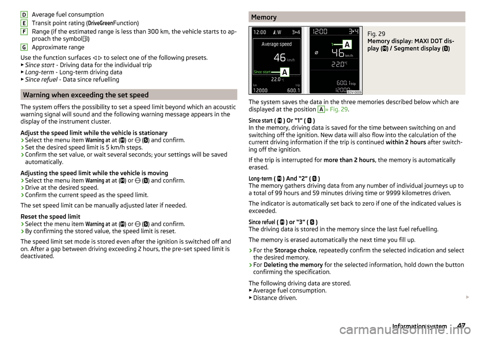
The system saves the data in the three memories described below which are
displayed at the position
A
» Fig. 29 .
Since start
(
) Or “1” (
)
In the memory, driving data is saved for the time between switching on and
switching off the ignition. New data will also flow into the calculation of the
current driving information if the trip is continued within 2 hours after switch-
ing off the ignition.
If the trip is interrupted for more than 2 hours, the memory is automatically
erased.
Long-term
( ) And “2” (
)
The memory gathers driving data from any number of individual journeys up to
a total of 99 hours and 59 minutes driving time or 9999 kilometres driven.
The indicator is automatically set back to zero if one of the indicated values is
exceeded.
Since refuel
( ) or “3” (
)
The driving data is stored in the memory since the last fuel refuelling.
The memory is erased automatically the next time you fill up.
›
For the Storage choice , repeatedly confirm the selected indication and select
the desired memory.
›
For Deleting the memory for the selected information, hold down the button
confirming the specification.
The following driving data are stored. ▶ Average fuel consumption.
▶ Distance driven.
47Information system
Page 51 of 336
▶Front Assist
▶ Lane Assist
▶ Rear Traffic Alert
▶ Assist system for blind spot monitoring
Service interval display
Introduction
This chapter contains information on the following subjects:
Displaying the distance and days until the next service interval
49
Service messages
49
Resetting the service interval display
49
The service interval display shows the kilometres or days until the next service
event.
Information regarding the service intervals » page 258.
Displaying the distance and days until the next service interval
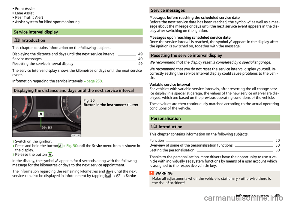
Fig. 30
Button in the instrument cluster
›
Switch on the ignition.
›
Press and hold the button
A
» Fig. 30 until the
Service
menu item is shown in
the display.
›
Release the button
A
.
In the display, the symbol appears for 4 seconds along with the following
message for the kilometres or days to the next service appointment.
The information regarding the remaining kilometres and days until the next service can also be displayed in Infotainment by tapping
→
→
ServiceService messages
Messages before reaching the scheduled service date
Before the next service date has been reached, the symbol
as well as a mes-
sage about the mileage or days until the next service event appears in the dis-
play after switching on the ignition.
Messages upon reaching scheduled service date
Once the service interval is reached, the symbol
appears in the display after
the ignition is switched on, together with the message:
Resetting the service interval display
We recommend that the display reset is completed by a specialist garage.
We recommend that you do not reset the service interval display yourself. In-
correctly setting the service interval display could cause problems to the vehi-
cle.
Variable service interval
For vehicles with variable service intervals, after resetting the oil change serv-
ice display in a specialist garage, the values of the new service interval are dis-
played, which are based on the previous operating conditions of the vehicle.
These values are then continuously matched according to the actual operating
conditions of the vehicle.
Personalisation
Introduction
This chapter contains information on the following subjects:
Function
50
Overview of some of the personalisation functions
50
Setting the personalisation
50
Thanks to the personalisation, more drivers have the opportunity to use a ve-
hicle with individually set system functions by means of a user account which
is assigned to the respective vehicle key.
WARNINGMake all adjustments when the vehicle is stationary - otherwise there is
the risk of accident!49Information system
Page 52 of 336
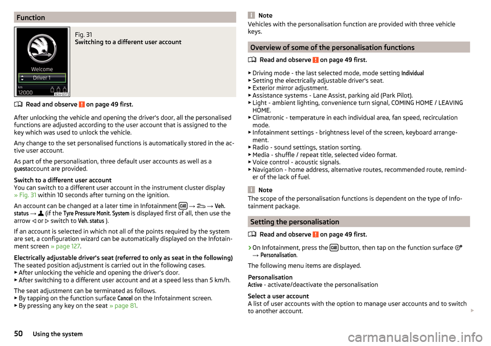
FunctionFig. 31
Switching to a different user account
Read and observe on page 49 first.
After unlocking the vehicle and opening the driver's door, all the personalised
functions are adjusted according to the user account that is assigned to the
key which was used to unlock the vehicle.
Any change to the set personalised functions is automatically stored in the ac- tive user account.
As part of the personalisation, three default user accounts as well as a
guest
account are provided.
Switch to a different user account
You can switch to a different user account in the instrument cluster display
» Fig. 31 within 10 seconds after turning on the ignition.
An account can be changed at a later time in Infotainment
→
→
Veh.status
→
(if the
Tyre Pressure Monit. System
is displayed first of all, then use the
arrow or
switch to
Veh. status
).
If an account is selected in which not all of the points required by the system
are set, a configuration wizard can be automatically displayed on the Infotain-
ment screen » page 127.
Electrically adjustable driver's seat (referred to only as seat in the following)
The seated position adjustment is carried out in the following cases. ▶ After unlocking the vehicle and opening the driver's door.
▶ After switching to a different user account and at a speed less than 5 km/h.
The seat adjustment can be terminated as follows.
▶ By tapping on the function surface
Cancel
on the Infotainment screen.
▶ By pressing any key on the seat » page 81.
NoteVehicles with the personalisation function are provided with three vehicle
keys.
Overview of some of the personalisation functions
Read and observe
on page 49 first.
▶Driving mode - the last selected mode, mode setting
Individual
▶Setting the electrically adjustable driver's seat.
▶ Exterior mirror adjustment.
▶ Assistance systems - Lane Assist, parking aid (Park Pilot).
▶ Light - ambient lighting, convenience turn signal, COMING HOME / LEAVING
HOME.
▶ Climatronic - temperature in each individual area, fan speed, recirculation
mode.
▶ Infotainment settings - brightness level of the screen, keyboard arrange-
ment.
▶ Radio - sound settings, station sorting.
▶ Media - shuffle / repeat title, selected video format.
▶ Voice control - acoustic signals.
▶ Navigation - home address, alternative routes, recommended route, remind-
er of the lack of fuel.
Note
The scope of the personalisation functions is dependent on the type of Info-
tainment package.
Setting the personalisation
Read and observe
on page 49 first.
›
On Infotainment, press the button, then tap on the function surface
→
Personalisation
.
The following menu items are displayed.
Personalisation
Active
- activate/deactivate the personalisation
Select a user account
A list of user accounts with the option to manage user accounts and to switch
to another account.
50Using the system
Page 53 of 336
■ - Account management with the following options:
■Rename user account
- rename the user account (not applicable to the
Guest
account)
■
Copy settings to another account
- copy the settings of an active user account to
another user account
■
Reset user account
- reset the selected user account to factory settings
Adjusting ■
Key assignment:
- options for assigning the vehicle key to the user account:
■
Manual
- detected vehicle key must be assigned to the active user account
manually
■
Automatic
- detected vehicle key automatically assigned to a different ac-
count of the active user account
■
Assign vehicle key to current user account
- manual assignment of the detected ve-
hicle key to the active user account - follow the instructions on the Infotain-
ment screen
■
Reset all
- reset the personalisation and the user accounts to factory settings
SmartGate
Introduction to the subject
Fig. 32
Information about SmartGate on
the ŠKODA websites
SmartGate is a system that transmits certain driving data (such as fuel con-
sumption, speed or similar) via Wi-Fi or Wi-Fi Direct.
The ŠKODA applications installed in a supported external device (e.g. tele-
phone, tablet) give the option to further transmit the received data.
Some ŠKODA applications can be displayed on the Infotainment display using a SmartLink connection » page 176.
Read in the QR code » Fig. 32or enter the following address in the web browser
to open the website with an overview of the available applications, compatible
devices and other information about SmartGate.
http://go.skoda.eu/connectivity-smartgate
CAUTION
■ To increase the access security to the transmitted vehicle data, once the
ŠKODA application has been started, you are requested to change the pass-
word/PIN code if the default password/PIN code has not yet been changed
» page 52 . It is not possible to start the ŠKODA application without having
made this change.■
ŠKODA accepts no responsibility for any problems caused by incompatibility
or improper functioning of the external devices.
connection to SmartGate using Wi-Fi
This type of connection is intended for external devices running Android and
iOS operating systems.
Connecting to an Android external device
›
Switch on the ignition.
›
Switch on Wi-Fi in the external device that is to be connected and search for
available Wi-Fi networks (see Owner´s Manual for the external device).
›
In the menu of the detected networks, select the “SmartGate_...” 1)
menu item.
›
Enter the password (vehicle identification number using uppercase let-
ters » page 52 ).
›
In the external device that is to be connected to, start the SmartGate appli-
cation.
›
Then follow the instructions in the manual, which is included in the
SmartGate application.
With SmartGate, a maximum of four external devices can be connected simul-
taneously using Wi-Fi, with as many launched ŠKODA applications as required.
Connecting to an external iOS device
›
Switch on the ignition.
›
Switch on Wi-Fi in the external device that is to be connected and search for
available Wi-Fi networks (see Owner´s Manual for the external device).
›
In the menu of the detected networks, select the “SmartGate_...” 1)
menu item.
1)
The last 6 characters of the vehicle identification number of your vehicle are displayed at position
....
51Information system
Page 54 of 336
›Enter the password (vehicle identification number using uppercase let-
ters » page 52 ).
With SmartGate, a maximum of four external devices can be connected simul-
taneously using Wi-Fi. In these external devices, up to four ŠKODA applications
can be started simultaneously.
Disconnection
The connection can be switched off in one of the following ways.›
Switch off the ignition for longer than 5 seconds (for vehicles with a starter
button, switch off the engine and open the driver's door).
›
End the connection in the SmartGate application.
›
Switch off Wi-Fi in the connected external device.
Automatic connection
If the communication device has already had a connection with SmartGate,
then the connection is automatically restored under the following conditions.
The ignition is switched on.
Wi-Fi is switched on in the external device that is to be connected to.
The external device that is to be connected to stores the password re-
quired for the connection check.
Connection to SmartGate using Wi-Fi direct
This type of connection is intended for external devices running the Android
operating system.
Establishing a connection
›
Switch on the ignition.
›
In the external device that is to be connected to, start the SmartGate appli- cation.
›
In the application, change the connection type to Wi-Fi direct.
›
Then follow the instructions in the manual, which is included in the
SmartGate application.
The password for the connection to SmartGate _... 1)
includes the last six digits
of the vehicle identification number » page 52.
With SmartGate, a maximum of two external devices can be connected simul-
taneously using Wi-Fi direct, with as many launched ŠKODA applications as re-
quired.
If you want to connect to SmartGate in a different vehicle, you must make a
new connection in the SmartGate application.
Disconnection
The connection can be switched off in one of the following ways.›
Switch off the ignition for longer than 5 seconds (for vehicles with a starter
button, switch off the engine and open the driver's door).
›
End the connection in the SmartGate application.
›
Switch off Wi-Fi in the connected external device.
Automatic connection
If the external device once had a connection with SmartGate, then the connec-
tion is automatically restored after the ignition is started.
SmartGate web interface
SmartGate parameters can be set in the SmartGate web interface.
The following address must be entered in the web browser of the external de-
vice that is connected with SmartGate.
HTTP://192.168.123.1
The setting changes are only effective after tapping the buttons “Save” →
“Reboot”.
Password/PIN code
The password for the Wi-Fi connection preset by the factory is the complete
vehicle identification number (entered in upper case); the PIN code for the Wi-
Fi direct connection is the last 6 digits of the vehicle identification number.
After changing the password/PIN, the connection to SmartGate must be re-es-
tablished on the external device to be connected using the new password or
new PIN code.
Changing the password for the Wi-Fi connection
›
Open the SmartGate web interface » page 52.
›
In the menu item “WPA / WPA2 key:”enter the new password (8 to 63 alpha-
numeric characters and special characters, small and capital letters) .
›
Confirm the password change by tapping on the “Save” button.
1)
The last 6 characters of the vehicle identification number of your vehicle are displayed at position
....
52Using the system
Page 56 of 336
WARNING■Never leave the key in the vehicle when you exit the vehicle. Unauthor-
ized persons (e.g. children) could lock the car, turn on the ignition or start
the engine - there is a danger of injury and accidents!■
When leaving the vehicle, never leave people who are not completely in-
dependent, such as children, unattended in the vehicle. These individuals
might not be able to leave the vehicle on their own or to help themselves.
Can be fatal at very high or very low temperatures!
CAUTION
■ Each key contains electronic components; therefore it must be protected
against moisture and severe shocks.■
Keep the keyway clean. Impurities (textile fibres, dust etc.) have a negative
effect on the functionality of the locking cylinder and ignition lock.
Unlocking/locking with the remote control key
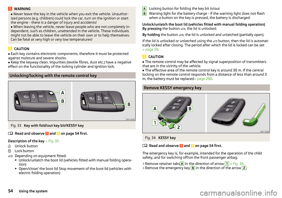
Fig. 33
Key with fold/out key bit/KESSY key
Read and observe
and on page 54 first.
Description of the key » Fig. 33
Unlock button
Lock button
Depending on equipment fitted:
▶ Unlock/unlatch the boot lid (vehicles fitted with manual folding opera-
tion)
▶ Open/close/ the boot lid Stop movement of the boot lid (vehicles with
electric folding operation)
Locking button for folding the key bit in/out
Warning light for the battery charge - if the warning light does not flash
when a button on the key is pressed, the battery is discharged.
Unlock/unlatch the boot lid (vehicles fitted with manual folding operation)
By pressing the button
, the lid is unlocked.
By holding the button
, the lid is unlocked and unlatched (partially open).
If the lid is unlocked or unlatched using the
button, then the lid is automat-
ically locked after closing. The period after which the lid is locked can be set
» page 59 .
CAUTION
■
The remote control may be affected by signal superposition of transmitters
that are in the vicinity of the vehicle.■
The effective area of the remote control key is around 30 m. If the central
locking on the remote control responds from a distance of less than around 3
m, the battery must be replaced » page 290.
Remove KESSY emergency key
Fig. 34
KESSY key
Read and observe
and on page 54 first.
The emergency key is, for example, intended for the operation of the child
safety, and for switching off/on the front passenger airbag.
›
Remove retainer tabs
A
in the direction of arrow
1
» Fig. 34 .
›
Remove the emergency key
B
in the direction of the arrow
2
.
AB54Using the system
Page 57 of 336
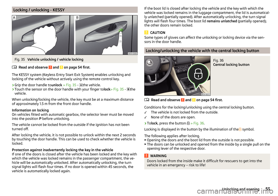
Locking / unlocking - KESSYFig. 35
Vehicle unlocking / vehicle locking
Read and observe
and on page 54 first.
The KESSY system (Keyless Entry Start Exit System) enables unlocking and
locking of the vehicle without actively using the remote control key.
›
Grip the door handle to unlock » Fig. 35 -
the vehicle.
›
Touch the sensor on the door handle with your finger to
lock» Fig. 35 -
the
vehicle.
When unlocking/locking the vehicle, the key must be at a maximum distance
of approximately 1.5 m from the front door handle.
Information on locking
On vehicles fitted with automatic gearbox, the selector lever must be moved
into the position P before unlocking.
The vehicle cannot be locked from the outside if the ignition has not been
turned off.
After locking the vehicle, it is not possible to unlock within the next 2 seconds
by touching the door handle. This can be used to check whether the vehicle is
locked.
Protection against inadvertently locking the key in the vehicle
If one of the doors is closed after the vehicle has been locked and the key with
which the vehicle was locked remains in the passenger compartment, the ve-
hicle will be automatically unlocked. After automatically unlocking, the turn
signal lights will flash four times. If no door is opened within 45 seconds, the
vehicle is automatically locked again.
If the boot lid is closed after locking the vehicle and the key with which the
vehicle was locked remains in the luggage compartment, the lid is automatical-
ly unlatched (partially opened). After automatically unlocking, the turn signal
lights will flash four times. The boot lid remains unlatched (partially opened);
the other doors remain locked.
CAUTION
Some types of gloves can affect the unlocking or locking device via the sen-
sors in the door handle.
Locking/unlocking the vehicle with the central locking button
Fig. 36
Central locking button
Read and observe and on page 54 first.
Conditions for the locking/unlocking using the central locking button.
The vehicle is not locked from the outside.
None of the doors are open.
›
To lock , press the button
» Fig. 36 .
Locking is displayed in the button by the illumination of the
symbol.
The following applies after locking. ▶ Opening the doors and the boot lid from the outside is not possible.
▶ The doors can be unlocked and opened from the inside by a single pull on the
opening lever of the respective door.
WARNINGDoors locked from the inside make it difficult for rescuers to get into the
vehicle in an emergency – risk to life!55Unlocking and opening