ESP SKODA SUPERB 2016 3.G / (B8/3V) Owner's Guide
[x] Cancel search | Manufacturer: SKODA, Model Year: 2016, Model line: SUPERB, Model: SKODA SUPERB 2016 3.G / (B8/3V)Pages: 336, PDF Size: 53.89 MB
Page 79 of 336

Automatic windscreen wiping during rain can be in the Infotainment menu
→ →
Mirrors and wipers
enabled / disabled .WARNINGAutomatic wiping during rain is only a support. The driver is not released
from the responsibility to set the function of the windscreen wipers man-
ually depending on the visibility conditions.
Note
■ If the wiping is carried out without interruption, the wiping speed varies de-
pending on the vehicle speed.■
The setting (activation/deactivation) of the automatic windscreen wiping in
the rain is stored (depending on the Infotainment type) in the active user ac-
count personalisation » page 49.
Rear window wipers and washers / reversing camera cleaning
system
Fig. 64
Operating the windscreen wipers
and washing system
Read and observe and on page 76 first.
The lever can be moved to the following positions » Fig. 64
Spraying and wiping the windscreen (sprung position) - after releasing the
control stalk, the wipers perform another 2 to 3 wiper strokes
Spraying the rear view camera (sprung position)
Windscreen wiping
Wipers and washers off
Automatic rear wiper
If the windscreen wiping is performed without interruption, then the automat-
ic regular intermittent wiping of the rear window takes place.
This function can be activated / deactivated in the Infotainment menu
→
→ Mirrors and wipers
.
Note
■
The rear window is wiped automatically if the windscreen wipers are on
when reverse gear is selected.■
The setting (activation/deactivation) of the automatic rear window wiping in
the rain is stored (depending on the Infotainment type) in the active user ac-
count personalisation » page 49.
Headlight cleaning system
Read and observe
and on page 76 first.
The headlights are cleaned with every first and after every tenth spraying of
the windscreen under the following conditions.
The ignition is switched on.
The low beam is switched on.
The outside temperature is about -12° C to +39° C.
To ensure the correct functioning of the system, even in winter, this needs to
be regularly cleared of snow and ice (e.g. using the de-icing spray).
Rear view mirror
Introduction
This chapter contains information on the following subjects:
Interior mirror dimming
78
Exterior mirrors
78WARNINGExterior mirrors increase the field of view, however, make objects appear
smaller and further away. Therefore, use the rear-view mirror to determine
the distances to the following vehicles. 77Lights and visibility
Page 80 of 336
WARNING■The mirrors with automatic dimming contain electrolyte fluid which may
leak if the mirror glass is broken - this can irritate skin, eyes and the respi-
ratory system.■
If your eyes or skin come into contact with the electrolyte fluid, immedi-
ately wash the affected area for a few minutes with plenty of water. Seek
medical assistance if required.
Interior mirror dimming
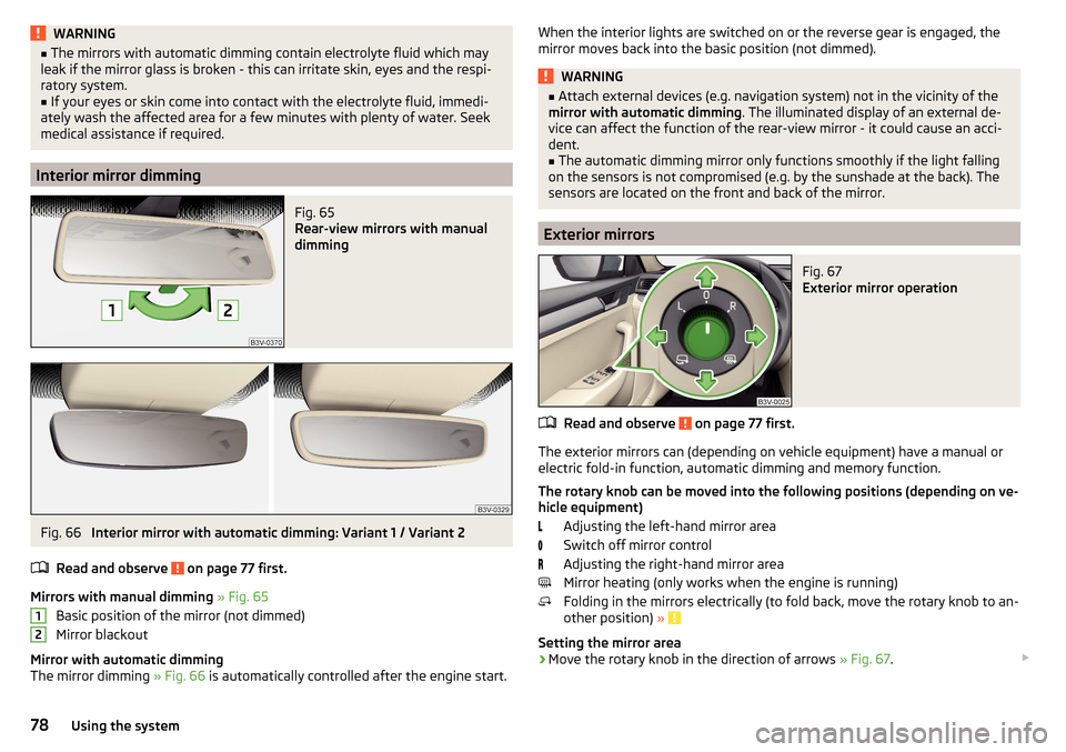
Fig. 65
Rear-view mirrors with manual
dimming
Fig. 66
Interior mirror with automatic dimming: Variant 1 / Variant 2
Read and observe
on page 77 first.
Mirrors with manual dimming » Fig. 65
Basic position of the mirror (not dimmed)
Mirror blackout
Mirror with automatic dimming
The mirror dimming » Fig. 66 is automatically controlled after the engine start.
12When the interior lights are switched on or the reverse gear is engaged, the
mirror moves back into the basic position (not dimmed).WARNING■ Attach external devices (e.g. navigation system) not in the vicinity of the
mirror with automatic dimming . The illuminated display of an external de-
vice can affect the function of the rear-view mirror - it could cause an acci-
dent.■
The automatic dimming mirror only functions smoothly if the light falling
on the sensors is not compromised (e.g. by the sunshade at the back). The
sensors are located on the front and back of the mirror.
Exterior mirrors
Fig. 67
Exterior mirror operation
Read and observe on page 77 first.
The exterior mirrors can (depending on vehicle equipment) have a manual or
electric fold-in function, automatic dimming and memory function.
The rotary knob can be moved into the following positions (depending on ve- hicle equipment)
Adjusting the left-hand mirror area
Switch off mirror control
Adjusting the right-hand mirror area
Mirror heating (only works when the engine is running)
Folding in the mirrors electrically (to fold back, move the rotary knob to an-
other position) »
Setting the mirror area
›
Move the rotary knob in the direction of arrows » Fig. 67.
78Using the system
Page 82 of 336
Seats and head restraints
Front seats
Introduction
This chapter contains information on the following subjects:
Manual adjustment
80
Electrical adjustment
80
Convenience operation of the front passenger seat
81
Memory Function of the electrically adjustable seat
81
Memory function of the remote control key
81
Folding front passenger seat
82
Armrest setting
82WARNING■ Only adjust the driver's seat when the vehicle is stationary – risk of acci-
dent!■
Caution when adjusting the seat! You may suffer injuries or bruises as a
result of adjusting the seat without paying proper attention.
Manual adjustment
Fig. 68
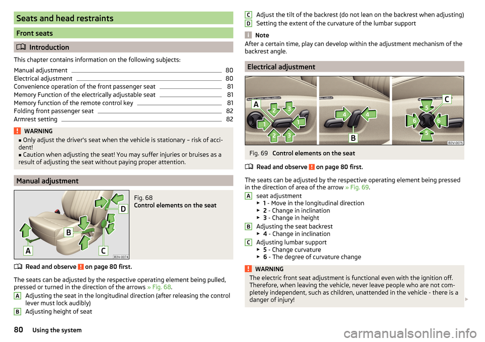
Control elements on the seat
Read and observe on page 80 first.
The seats can be adjusted by the respective operating element being pulled,
pressed or turned in the direction of the arrows » Fig. 68.
Adjusting the seat in the longitudinal direction (after releasing the control
lever must lock audibly)
Adjusting height of seat
ABAdjust the tilt of the backrest (do not lean on the backrest when adjusting)
Setting the extent of the curvature of the lumbar support
Note
After a certain time, play can develop within the adjustment mechanism of the
backrest angle.
Electrical adjustment
Fig. 69
Control elements on the seat
Read and observe
on page 80 first.
The seats can be adjusted by the respective operating element being pressed in the direction of area of the arrow » Fig. 69.
seat adjustment
▶ 1 - Move in the longitudinal direction
▶ 2 - Change in inclination
▶ 3 - Change in height
Adjusting the seat backrest
▶ 4 - Change in inclination
Adjusting lumbar support
▶ 5 - Change curvature
▶ 6 - The degree of curvature change
WARNINGThe electric front seat adjustment is functional even with the ignition off.
Therefore, when leaving the vehicle, never leave people who are not com-
pletely independent, such as children, unattended in the vehicle - there is a
danger of injury! CDABC80Using the system
Page 83 of 336
Note■If the inclination angle of the seat backrest relative to the seat surface is
greater than approx. 110°, then it is not possible for safety reasons to save this
setting in the memory of the electrically adjustable seats or the remote control
key.■
On vehicles with personalisation, the driver's seat setting is stored in the ac-
tive user account personalisation » page 49.
Convenience operation of the front passenger seat
Fig. 70
Operating elements on the front
passenger's seat
Read and observe on page 80 first.
The front passenger seat can also be operated from the rear seats, by pressing
the respective operating element in the direction of the arrows » Fig. 70.
Adjusting the angle of the seat backrest
Adjusting a seat in a forward/back direction
Memory Function of the electrically adjustable seat
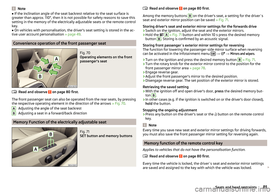
Fig. 71
SET button and memory buttons
ABRead and observe on page 80 first.
Among the memory buttons
B
on the driver's seat, a setting for the driver´s
seat and exterior mirror position can be saved » Fig. 71.
Storing driver's seat and exterior mirror settings for the forwards drive
›
Switch on the ignition, adjust the seat and the exterior mirrors.
›
Hold the
A
» Fig. 71 button and within 10 s press the desired memory
button
B
. Storing is confirmed by an acoustic signal.
Storing front passenger´s exterior mirror settings for reversing
The function for lowering the passenger-side mirror surface when reversing can be activated in the Infotainment menu
→
→
Mirrors and wipers
.
›
Turn on the ignition and press the desired memory button
B
» Fig. 71 .
›
Turn the rotary knob for the exterior mirror control to the position for the
front passenger mirror area » page 78.
›
Engage reverse gear.
›
Adjust the front passenger's mirror to the desired position.
›
Disengage reverse gear. The set position of the exterior mirror is stored.
Retrieving the saved setting
›
With the ignition off and open driver's door, press the desired memory but-
ton
B
.
›
In other cases (e.g. if the ignition is switched on or the driver's door closed),
hold the button.
Stopping the ongoing adjustment
›
Press any button on the driver's seat or the button on the remote control
key.
Note
Every time you save new seat and exterior mirror settings for driving forwards,
you must also save the front passenger mirror setting for reversing again.
Memory function of the remote control key
Applies to vehicles that do not have the personalisation function.
Read and observe
on page 80 first.
Every time the vehicle is locked, the driver´s seat and exterior mirror settingsare saved and assigned to the key with which the vehicle was locked.
81Seats and head restraints
Page 85 of 336

Rear seats
Introduction
This chapter contains information on the following subjects:
Seat backrests
83
Fold down armrest
83
Seat backrests
Fig. 74
Folding down the seat backrests from the forward from the pas-
senger compartment
Fig. 75
Fold the backrest forward from
the luggage compartment
Before folding the seat backrests forwards, adapt the position of the front
seats in such a way that they are not damaged by the folded seat backrests. If
necessary, remove the rear headrests » page 84,
Folding forwards from the passenger compartment
›
Place the outer seat belt behind the raised edge
A
» Fig. 74 .
›
Push the release lever
B
in the direction of arrow
1
and fold down the seat
backrest in the direction of arrow
2
.
Fold forward from the luggage compartment
On vehicles with a net partition, the left and then the right and middle rear
seat backrest must first be unlocked. The net partition must be rolled up in the
housing.›
Pull the corresponding lever in the direction of the arrow » Fig. 75. The re-
spective seat backrest is unlocked or folded forward.
Folding backwards
›
Place the outer seat belt behind the raised edge
A
» Fig. 74 .
›
Lift the seat backrest against the direction of arrow
2
until the release lever
B
audibly locks. Check this by pulling on the seat backrest.
›
Make sure that the red pin
C
is hidden.
WARNING■
The seat backrests in the occupied rear seats must be properly engaged.■When transporting objects in the luggage compartment that has been en-
larged by folding the backrest forward, ensure the safety of the passengers
transported on the other rear seats.■
The seat backrests must be securely latched in position so that no ob-
jects from the luggage compartment can slip into the passenger compart-
ment under sudden braking – risk of injury.
CAUTION
When operating the seat backrests, the seat belts must not be pinched - there
is a risk of damage to the seat belts.
Fold down armrest
Fig. 76
Fold down armrest
The armrest can be folded down in the direction of the arrow » Fig. 76.
83Seats and head restraints
Page 101 of 336

Cigarette lighterFig. 114
Cigarette lighter: in the front centre console/in the rear centre
console
Read and observe
on page 98 first.
›
To use , open the respective storage compartment and push in the lighter un-
til it stops » Fig. 114.
›
Wait until the glowing lighter protrudes, remove it immediately and use.
›
Put the lighter back in the socket and close the storage compartment.
WARNING■
The cigarette lighter also works if the ignition is switched off. When leav-
ing the vehicle, never leave people who are not completely independent,
such as children, unattended in the vehicle - there is a risk of burning, fire
or damage to the vehicle interior.■
Be careful when using the cigarette lighter - it can cause burns.
Note
The cigarette lighter socket can also be used as a 12 volt socket.
Tablet holder
Introduction
This chapter contains information on the following subjects:
Attaching the rear headrests
99
Attach to the storage compartment in the rear armrest
100
Handling the holder
100External devices (e.g. tablet, smartphone etc.) measuring min. 122 mm and
max. 195 mm can be secured in the holder.
The maximum permissible load of the compartment is 750 g.
CAUTION
Never exceed the maximum permissible load of the holder - there is a risk of
damage or functional impairment.
Attaching the rear headrests
Fig. 115
Inserting: Adapter / holder
Fig. 116
Removing: Holder / adapter
Read and observe
on page 99 first.
›
To insert , attach the opened adapter to the guide rods of the front headrest
and clip in the direction of arrow
1
» Fig. 115 » .
›
Clip in the holder in the direction of arrow
2
into the adapter.
›
To remove , pull on the securing tab
A
in direction of arrow
3
and take the
holder in direction of arrow
4
out of the adapter » Fig. 116.
99Practical features
Page 103 of 336

Transport of cargo
Luggage compartment
Introduction
This chapter contains information on the following subjects:
Fastening elements
101
Fixing nets
102
Foldable hook
103
Fasten the flooring
103
Floor covering on both sides
103
Net on the luggage compartment cover
103
Luggage compartment cover
104
Roll-up cover
105
Roll-up cover - automatic rolling-up
105
Side storage compartment and trays
106
Cargo element
106
Storage compartments under the floor covering
107
Multi-function pocket
108
Removable light
109
Class N1 vehicles
109
When transporting heavy objects, the driving characteristics change due to the
shift in centre-of-gravity. The speed and style of driving must be adjusted ac-
cordingly.
When transporting cargo the following the instructions must be adhered to
▶ Distribute the load evenly in the luggage compartment and secure it with
suitable lashing straps to the lashing eyes or securing nets so that they can-
not slip.
▶ Place heavy objects as far forward as possible.
▶ Tyre pressure is to match the load.
In the event of an accident, even small and light objects gain so much kinetic
energy that they can cause severe injuries.
The magnitude of the kinetic energy is dependent on the speed at which the
vehicle is travelling and the weight of the object.
Luggage compartment light
The light switches on/off when the boot lid is opened or closed.
If the boot lid is open and the ignition switched off, the light will extinguish
automatically after around 10 minutes.WARNING■ Never exceed the maximum permissible load of the respective fasteners,
nets, hooks etc. Heavy objects were not secured sufficiently – risk of injury!■
Do not exceed the permissible axle loads and permissible gross weight of
the vehicle – risk of accident!
■
An unfixed or improperly fixed load can slip during a sudden manoeuvre
or an accident - danger of injury!
■
Loose cargo could hit a deployed airbag and injure occupants – danger of
death!
■
When transporting loads in the luggage compartment that has been en-
larged by folding the rear seats forward, ensure the safety of the passen-
gers transported on the other rear seats .
CAUTION
■ Never exceed the maximum permissible load of the respective fasteners,
nets, hooks etc. - these could be damaged.■
Make sure that the heating elements of the rear window heater, the ele-
ments of the integrated aerial in the rear window or in the rear side windows
are not damaged by abrasive items.
■
Do not place sharp objects in the nets and storage compartments in the lug-
gage compartment - there is a risk of damage to the net as well as the com-
partments.
■
Put the items in the storage compartments carefully and not load these
punctiform - there is a risk of damage to the compartments.
Fastening elements
Fig. 120
Fasteners: Variant 1 / Variant 2
101Transport of cargo
Page 116 of 336
WARNING■The blower should always be on to prevent the windows from misting.
Otherwise there could be an accident.■
Under certain circumstances, air at a temperature of about 5 °C can flow
out of the vents when the cooling system is switched on.
Note
■ The air inlet in front of the windscreen must be free of e.g. ice, snow or
leaves to ensure that the heating and cooling system operates properly.■
After switching on the cooling Condensation from the evaporator of the air
conditioning may drip down and form a puddle below the vehicle. This is not a
leak!
■
If the coolant temperature is too high, the cooling system is switched off to
ensure that the engine cools down.
Heating and manual air conditioning
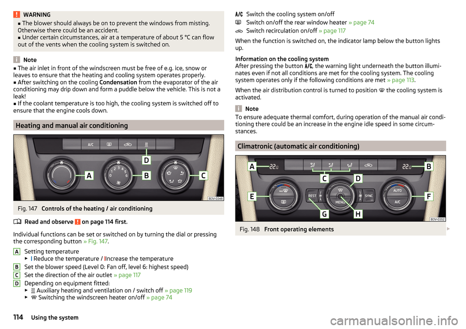
Fig. 147
Controls of the heating / air conditioning
Read and observe
on page 114 first.
Individual functions can be set or switched on by turning the dial or pressing the corresponding button » Fig. 147.
Setting temperature
▶ Reduce the temperature /
Increase the temperature
Set the blower speed (Level 0: Fan off, level 6: highest speed)
Set the direction of the air outlet » page 117
Depending on equipment fitted:
▶ Auxiliary heating and ventilation on / switch off
» page 119
▶ Switching the windscreen heater on/off
» page 74
ABCDSwitch the cooling system on/off
Switch on/off the rear window heater » page 74
Switch recirculation on/off » page 117
When the function is switched on, the indicator lamp below the button lights up.
Information on the cooling system
After pressing the button
, the warning light underneath the button illumi-
nates even if not all conditions are met for the cooling system. The cooling
system operates only if the following conditions are met » page 113.
When the air distribution control is turned to position
the cooling system is
activated.
Note
To ensure adequate thermal comfort, during operation of the manual air condi-
tioning there could be an increase in the engine idle speed in some circum-
stances.
Climatronic (automatic air conditioning)
Fig. 148
Front operating elements
114Using the system
Page 117 of 336
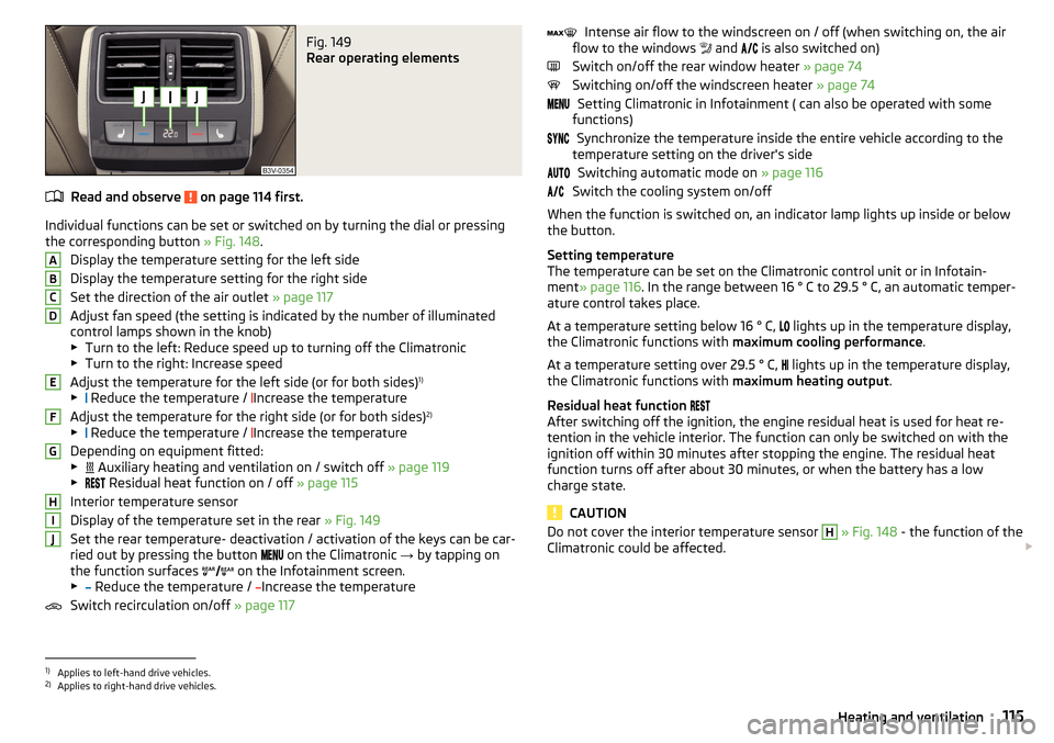
Fig. 149
Rear operating elements
Read and observe on page 114 first.
Individual functions can be set or switched on by turning the dial or pressingthe corresponding button » Fig. 148.
Display the temperature setting for the left side
Display the temperature setting for the right side
Set the direction of the air outlet » page 117
Adjust fan speed (the setting is indicated by the number of illuminated
control lamps shown in the knob)
▶ Turn to the left: Reduce speed up to turning off the Climatronic
▶ Turn to the right: Increase speed
Adjust the temperature for the left side (or for both sides) 1)
▶ Reduce the temperature /
Increase the temperature
Adjust the temperature for the right side (or for both sides) 2)
▶ Reduce the temperature /
Increase the temperature
Depending on equipment fitted:
▶ Auxiliary heating and ventilation on / switch off
» page 119
▶ Residual heat function on / off
» page 115
Interior temperature sensor
Display of the temperature set in the rear » Fig. 149
Set the rear temperature- deactivation / activation of the keys can be car-
ried out by pressing the button on the Climatronic
→ by tapping on
the function surfaces on the Infotainment screen.
▶ Reduce the temperature /
Increase the temperature
Switch recirculation on/off » page 117
ABCDEFGHIJIntense air flow to the windscreen on / off (when switching on, the air
flow to the windows and is also switched on)
Switch on/off the rear window heater » page 74
Switching on/off the windscreen heater » page 74
Setting Climatronic in Infotainment ( can also be operated with some
functions)
Synchronize the temperature inside the entire vehicle according to the
temperature setting on the driver's side
Switching automatic mode on » page 116
Switch the cooling system on/off
When the function is switched on, an indicator lamp lights up inside or below
the button.
Setting temperature
The temperature can be set on the Climatronic control unit or in Infotain-
ment » page 116 . In the range between 16 ° C to 29.5 ° C, an automatic temper-
ature control takes place.
At a temperature setting below 16 ° C, lights up in the temperature display,
the Climatronic functions with maximum cooling performance .
At a temperature setting over 29.5 ° C, lights up in the temperature display,
the Climatronic functions with maximum heating output.
Residual heat function
After switching off the ignition, the engine residual heat is used for heat re-
tention in the vehicle interior. The function can only be switched on with the
ignition off within 30 minutes after stopping the engine. The residual heat
function turns off after about 30 minutes, or when the battery has a low
charge state.
CAUTION
Do not cover the interior temperature sensor H » Fig. 148 - the function of the
Climatronic could be affected. 1)
Applies to left-hand drive vehicles.
2)
Applies to right-hand drive vehicles.
115Heating and ventilation
Page 123 of 336
Infotainment
Introductory information
Important information
Introduction to the subject
WARNING■Only use Infotainment in such a way that you have control of the vehicle
in every traffic situation (e.g. Do not write text messages while driving, do
not couple or connect the telephone, do not work with the contact list, do
not enter any destinations, do not connect WLAN or SmartLink etc.)- Other-
wise there is a risk of an accident!■
Always route the connection cable of the external device in such a way
that it does not restrict you when driving.
WARNING■ Adjust the volume to ensure that acoustic signals from outside the vehi-
cle, e.g. sirens from emergency vehicles, can be heard at all times.■
High volumes can cause hearing damage!
CAUTION
In some countries, some Infotainment features can no longer be selected
when the vehicle is running faster than a certain speed. This is not a malfunc-
tion, but complies with the national legal regulations.
Mobile telephones and applications
Fig. 157
QR code with reference to web
pages for checking the compati-
bility of devices
The availability of some of the functions described in this Owner's Manual
depends on the type of device to be connected and the applications installed
in it.
Mobile telephones
On the ŠKODA pages, check to see if Infotainment is compatible with the se-
lected mobile telephones. This check takes place by reading the QR code
» Fig. 157 or after typing the following address into the web browser.
http://go.skoda.eu/compatibility
Due to the multitude of mobile telephones as well as the ongoing develop-
ment of these devices, ŠKODA AUTO cannot always ensure compatibility with
Infotainment unconditionally. It is always recommended to physically check
the function on the associated vehicle, including the ŠKODA Partners, before-
hand.
Only those versions of the selected telephones will be tested and supported
which originate from the official distribution network. The same also applies to
their firmware and software.
The functions of the mobile telephone to be tested may differ from the same
type of mobile telephone depending on the specification for the respective
country or the specific service.
Mobile telephones with the operating system and in the version available at
the time of these tests will be tested. In this regard, it could be the case that
the functions of a mobile telephone may differ with a different operating sys-
tem version compared to the one used with the tested telephone.
ŠKODA AUTO can accept no responsibility for the continuous changes made by the mobile telephone manufacturers and application vendors.
ŠKODA AUTO does not accept any liability for any damage to Infotainment or
the vehicle due to the use of incorrect or illegal applications or the improper or
unauthorized use of mobile telephones.
Applications
Applications can be installed in external devices (e.g. Mobile, tablet) making it
possible to display additional information in the Infotainment screen or to op-
erate Infotainment.
Due to the variety of applications as well as their ongoing development, the
available applications may not work in all external devices. ŠKODA AUTO can
accept no liability for their proper function.
Applications, their use and the required data connection may be chargeable. 121Introductory information